Table of Contents
Advertisement
Advertisement
Table of Contents

Related Manuals for HikRobot MV-CL042-91CM


Summary of Contents for HikRobot MV-CL042-91CM
- Page 1 Camera Link Line Scan Camera User Manual...
- Page 2 The information contained in the Manual is subject to change, without notice, due to firmware updates or other reasons. Please find the latest version of this Manual at the Hikrobot website (https://en.hikrobotics.com/). Please use this Manual with the guidance and assistance of professionals trained in supporting the Product.
- Page 3 ANY NUCLEAR EXPLOSIVE OR UNSAFE NUCLEAR FUEL-CYCLE, OR IN SUPPORT OF HUMAN RIGHTS ABUSES. THE PERFORMANCE DATA IN THIS PUBLICATION IS BASED ON HIKROBOT'S INTERNAL RESEARCH/EVALUATION. ACTUAL DATA MAY VARY DEPENDING ON SPECIFIC CONFIGURATIONS AND OPERATING CONDITIONS AND HIKROBOT SHALL NOT BEAR THE CONSEQUENCES ARISING THEREFROM.
- Page 4 Camera Link Line Scan Camera User Manual upon the purchase of equivalent new equipment, or dispose of it at designated collection points. more information see: http://www.recyclethis.info 2006/66/EC (battery directive): This product contains a battery that cannot be disposed of as unsorted municipal waste in the European Union.
- Page 5 Camera Link Line Scan Camera User Manual device, follow the signs on the device and in the manual, and all safety instructions described in the manual. ● The note, caution and danger items in the manual do not represent all the safety instructions that should be observed, but only serve as a supplement to all the safety instructions.
- Page 6 Camera Link Line Scan Camera User Manual when cleaning. ● Keep clean of the device’s image acquisition window. It is recommended to use cleaning water to wipe off the dust. ● If the device does not work properly, please contact your dealer or the nearest service center.
- Page 7 ● Use a shielded network cable to connect to the device. If you use a self-made network cable, make sure that the shielding shell at the aviation head is well connected to the aluminum foil or metal braid of the shielding cable. Contact Information Hangzhou Hikrobot Co., Ltd. E-mail: tech_support@hikrobotics.com Website: https://en.hikrobotics.com/...
-
Page 8: Table Of Contents
Camera Link Line Scan Camera User Manual Contents Chapter 1 Overview ........................... 1 1.1 Introduction ......................... 1 1.2 Key Feature .......................... 1 Chapter 2 Appearance ........................2 Chapter 3 I/O Connector and Indicator..................5 3.1 Power and I/O Connector ....................5 3.2 Indicator .......................... - Page 9 Camera Link Line Scan Camera User Manual 7.8 IO Test Tool ........................38 Chapter 8 Trigger Output ....................... 40 8.1 Select Output Signal ......................40 8.2 Set Output Signal ......................41 8.2.1 Enable Line Inverter ....................41 8.2.2 Enable Strobe Signal .................... 41 Chapter 9 I/O Electrical Features and Wiring ................
- Page 10 Camera Link Line Scan Camera User Manual 10.14 Set AOI ........................... 72 10.15 Set Color Transformation Control ................73 10.16 Set Hue .......................... 75 10.17 Set Saturation....................... 75 10.18 Set Super Palette Control ................... 76 10.19 Set LUT .......................... 77 10.20 Set Shading Correction ....................
- Page 11 Camera Link Line Scan Camera User Manual Appendix A Device Parameter Index .................... 98 Appendix B Serial Communication Command List..............105 Appendix C Revision History ....................... 132...
-
Page 12: Chapter 1 Overview
Camera Link Line Scan Camera User Manual Chapter 1 Overview 1.1 Introduction The Camera Link line scan camera uses the Camera Link interface to transmit non-compressed images in real time, and it can be set parameters via the client software, the frame grabber software, SDK, etc. -
Page 13: Chapter 2 Appearance
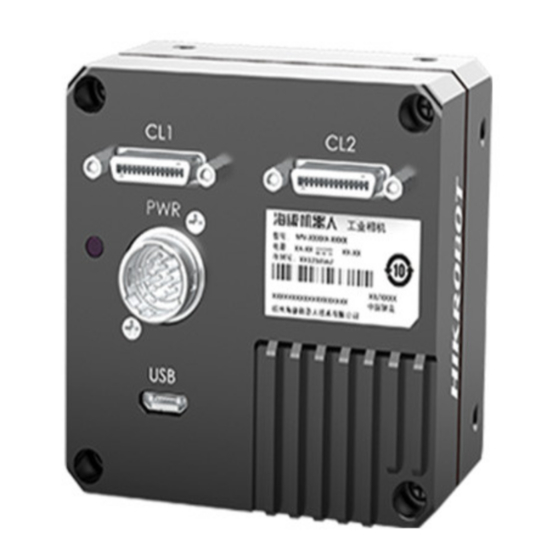
Camera Link Line Scan Camera User Manual Chapter 2 Appearance Note ● The device’s appearance may differ by device models. The image below is for reference only. For specific appearance and dimension, please refer to the device’s specification for details. ●... - Page 14 Camera Link Line Scan Camera User Manual Figure 2-3 Appearance (Type III) Figure 2-4 Appearance (Type IV)
- Page 15 Refer to the table below for the relation between device model and device appearance type. Table 2-2 Device Model and Appearance Type Device Model Device Appearance Type MV-CL042-91CM/CC Type I device MV-CL084-90CM, MV-CL086-90CC Type II device MV-CL086-91CC, MV-CL084-91CM-PRO, Type III device...
-
Page 16: Chapter 3 I/O Connector And Indicator
Camera Link Line Scan Camera User Manual Chapter 3 I/O Connector and Indicator 3.1 Power and I/O Connector All Camera Link line scan cameras have a 12-pin P10 connector, as shown below. However, the specific pin definitions differ by device models. Currently, two types of pin definitions are available. - Page 17 Camera Link Line Scan Camera User Manual Signal I/O Signal Source Description LINE3_P Line 3+ Differential input/output IO 3+ LINE3_N Line 3- Differential input/output IO 3- LINE4_P Line 4+ Differential input/output IO 4+ LINE1_P Line 1+ Differential input/output IO 1+ LINE1_N Line 1- Differential input/output IO 1-...
-
Page 18: Indicator
Camera Link Line Scan Camera User Manual 3.2 Indicator The device’s indicator is used to indicate the operation status of the device. Note When the indicator is flashing rapidly or flashing slowly, its unlit interval is 0.2 sec or 1 sec respectively. -
Page 19: Chapter 4 Installation
Camera Link Line Scan Camera User Manual Chapter 4 Installation 4.1 Installation Preparation You need to prepare following accessories before device installation. Table 4-1 Accessories Name Quantity Description Power It refers to the 12-pin power and I/O cable that you Cable need to purchase separately. - Page 20 Camera Link Line Scan Camera User Manual Camera Link cable according to the device’s interface and frame grabber model you use, and connect the device’s Camera Link interfaces to respective interfaces of the frame grabber. ● The device has 2 Camera Link interfaces, and it can transmit data via 1 or 2 Camera Link interface(s).
-
Page 21: Chapter 5 Device Connection
Camera Link Line Scan Camera User Manual Chapter 5 Device Connection 5.1 Install Frame Grabber Software The frame grabber software is used to set frame grabber parameters, view and set the device’s parameters, and acquire images. Steps 1. Get the installation package of the frame grabber software and drivers from frame grabber supplier. -
Page 22: Install Mvs Client Software
Camera Link Line Scan Camera User Manual Table 5-2 Parameters of Matrox Frame Grabber Frame Grabber Parameters Device Parameters Pixel Clock Frequency Pixel Clock Camera Link config Configuration Mode Taps Tap Number Device Tap Configuration Tap Geometry 5.3 Install MVS Client Software MVS client software is used to connect and set device’s parameters, and acquire images. -
Page 23: Connect Device To Mvs Client Software
Camera Link Line Scan Camera User Manual Figure 5-2 Default Settings 5. Keep default settings, and click Next. 6. Finish the installation according to the interface prompts. 5.4 Connect Device to MVS Client Software Steps 1. Run the MVS client software. 2. -
Page 24: Chapter 6 Quick Started With Mvs
Camera Link Line Scan Camera User Manual Chapter 6 Quick Started with MVS 6.1 Client Software Layout After connecting to the device, the client software can read the its attributes and display them. Figure 6-1 Main Window Note For specific main window of the client software, please refer to the actual one you got. Table 6-1 Main Window Description Name Description... - Page 25 Camera Link Line Scan Camera User Manual Name Description You can view and set features of the selected device, Feature Panel and perform operations such as importing, exporting, and saving features. Click in the device’s feature panel to unfold the specific parameters, and set them according to actual demands.
-
Page 26: Transport Layer Control
Camera Link Line Scan Camera User Manual Feature Name Description Transport Layer You can view and set the parameters of the device’s transport Control layer. User Set Control You can save or load the device’s parameters. 6.2 Transport Layer Control The device’s tap geometry should match with that of the frame grabber, and inconsistent parameters may lead to image exception. -
Page 27: Set Serial Port Parameters
Camera Link Line Scan Camera User Manual can view serial port information via the MVS client software or PC’ s device manager. Via MVS Client Software After connecting the device, the MVS client software displays the serial port information in the device list, as shown below. - Page 28 Camera Link Line Scan Camera User Manual Note ● The default value of the device’s baud rate is 9600 bps. ● The device’s parameters can be set via the MVS client software, frame grabber software or serial port tool, but you cannot use them at same time. The serial port tool can detect the device status, configure a valid serial port for the detected device, and configure parameters for the detected device.
-
Page 29: Chapter 7 Image Acquisition
Camera Link Line Scan Camera User Manual Chapter 7 Image Acquisition 7.1 Set Line Rate Line rate refers to the image line number that is output by the device per second. The frame rate of the device is proportional to its line rate, and is inversely proportional to the image height, that is, Fps = Lps (line rate)/Height (image height). -
Page 30: Set Frame Timeout
Camera Link Line Scan Camera User Manual The device supports selecting different methods of reading image data, including frame scan and line scan. Go to Acquisition Control → Scan Mode to select it according to actual demands. ● Frame Scan: The device outputs a frame of image after its outputted line quantity reaches configured image height. -
Page 31: Set Line Discard Function
Camera Link Line Scan Camera User Manual Parameter Description reach the image height (height parameter), the SDK will not output the image, and the SDK will wait for the line data until it reaches the image height before outputting the image. When the number of lines output by the device reaches the configured image height (height parameter) within the frame timeout period, and one frame of image will be output. -
Page 32: Set Trigger Mode
Camera Link Line Scan Camera User Manual Line Enable is disabled. ● The external device sends line trigger signal matching actual image height if Abnormal Line Enable is enabled. Figure 7-4 Set Line Discard Function 7.5 Set Trigger Mode The device has 4 types of trigger modes, including internal trigger mode, line trigger mode, frame trigger mode, and line + frame trigger mode. - Page 33 Camera Link Line Scan Camera User Manual source. ● In line + frame trigger mode, when the trigger source selected by the frame trigger and the line trigger and the trigger-related parameters are the same, the first signal of trigger source will be used as the frame trigger signal to make the device start to acquire images, and the subsequent signals as line trigger signal to acquire images per lines until the processing of one frame of image is completed, and then the processing of the...
- Page 34 Camera Link Line Scan Camera User Manual Set and Execute Software Trigger In software trigger, the software sends trigger signal to the device via GigE interface to acquire images. Steps 1. Go to Acquisition Control → Trigger Selector, and select Frame Burst Start as Trigger Selector.
- Page 35 Camera Link Line Scan Camera User Manual When selecting bi-directional configurable line as the hardware trigger source, you need to make sure that its line mode is input. Go to Digital IO Control, select specific line as Line Selector, and Input as Line Mode. Note Here we take Line 2 as an example to introduce how to set bi-directional configurable line as the hardware trigger source.
- Page 36 Camera Link Line Scan Camera User Manual Set and Execute Shaft Encoder Control If the device enables the line trigger, you can select Encoder Module Out as trigger source. At this time, the device will receive signal A and signal B with phase difference. After internal computing, the outputted signal can be used as device’s trigger signal.
- Page 37 Camera Link Line Scan Camera User Manual Figure 7-10 Process Logic Note Phase A and phase B of the encoder corresponds 4 signals each, as shown below. 3. Set Encoder Counter Mode. ● Ignore Direction means that both forward and backward direction will count. ●...
- Page 38 Camera Link Line Scan Camera User Manual 5. (Optional) Set Encoder Max Reverse Counter to avoid outputting images if the object moves backward accidently during measurement, and click Execute in Encoder Reverse Counter Reset to let the device to output images again. Set and Execute Frequency Converter Control If the device enables the frame trigger or the line trigger, you can select Frequency Converter as trigger source.
- Page 39 Camera Link Line Scan Camera User Manual Some device models support displaying trigger line rate. Note ● Parameters of trigger line rate and resulting trigger line rate may differ by device models. ● Make sure that line trigger is enabled and input source value of frequency converter control and trigger source value of acquisition control is the same before viewing trigger line rate.
- Page 40 Camera Link Line Scan Camera User Manual Figure 7-14 Set and Execute Frame Grabber Trigger Set and Execute Free Trigger If the device enables the frame trigger or line trigger, you can select Anyway as trigger source to enable the free trigger. At this time, the device can receive signals of all trigger sources.
-
Page 41: Set Trigger Related Parameters
Camera Link Line Scan Camera User Manual 7.7 Set Trigger Related Parameters If the device enables the frame trigger or line trigger, you can set trigger related parameters, including acquisition burst frame count, trigger activation, trigger delay, trigger cache, and trigger debouncer. Note ●... - Page 42 Camera Link Line Scan Camera User Manual Trigger Source Frame Shaft Frequency Hardware Free Grabber Encoder Converter Trigger Trigger Trigger Control Control Trigger Parameters Line Trigger Cache √ √ √ √ √ Trigger Debouncer √ × × √ √ Set Acquisition Burst Frame Count If the device enables the frame trigger, you can set the acquisition burst frame count.
- Page 43 Camera Link Line Scan Camera User Manual Figure 7-17 Sequence Diagram of Acquisition Burst Frame Count Set Trigger Activation The device supports triggering image acquisition in the rising edge, falling edge, level high, level low or any edge of the external signal. Go to Acquisition Control → Trigger Activation, and select Rising Edge, Falling Edge, Level High or Level Low as Trigger Activation.
- Page 44 Camera Link Line Scan Camera User Manual Figure 7-18 Edge Trigger in Frame Trigger ● When level high or level low is selected as Trigger Activation, the device will be triggered according to selected method. Figure 7-19 Level Trigger in Frame Trigger Set Trigger Activation in Line Trigger In the line trigger mode, the trigger activation is related with Exposure Mode.
- Page 45 Camera Link Line Scan Camera User Manual Figure 7-20 Set Trigger Activation in Line Trigger Note The trigger width function may differ by device models. Set Trigger Delay The trigger delay function allows the device to add a delay between the receipt of trigger signal and the moment the trigger becomes active.
- Page 46 Camera Link Line Scan Camera User Manual Figure 7-22 Set Trigger Delay under Line Trigger Figure 7-23 Sequence Diagram of Trigger Delay Note The sequence diagram above uses rising edge as trigger activation. Set Frame/Line Trigger Cache Note ● The frame/line trigger cache function may differ by device models. ●...
- Page 47 Camera Link Line Scan Camera User Manual Figure 7-24 Set Trigger Cache in Frame Trigger If the device receives the 1st trigger signal first, and the device receives the 2nd trigger signal during processing the 1st trigger signal. ● Disable Trigger Cache Enable: the 2nd trigger signal will be filtered without processing. Figure 7-25 Second Frame Filtered ●...
- Page 48 Camera Link Line Scan Camera User Manual If the 1st frame image’s exposure time of the 2nd trigger signal is earlier than the device’s last frame creation time of the 1st trigger signal, and then the device will delay this exposure time.
-
Page 49: Io Test Tool
Camera Link Line Scan Camera User Manual Set Trigger Debouncer The trigger debouncer function allows the device to filter out unwanted short external trigger signal that is input to the device. Go to Digital IO Control → Line Debouncer Time, and enter Line Debouncer Time according to actual demands. - Page 50 Camera Link Line Scan Camera User Manual For some device models, the device supports checking whether the line or frame signal it received is stable or not via the IO test tool. Go to Digital IO Control, and enable IO Test Tool Enable (Line) according to actual demands.
-
Page 51: Chapter 8 Trigger Output
Camera Link Line Scan Camera User Manual Chapter 8 Trigger Output 8.1 Select Output Signal Note The selectable output signal line may differ by device models. The device has multiple differential output lines or bi-directional configurable lines. The method of setting bi-directional configurable line as output line as follows: Steps 1. -
Page 52: Set Output Signal
Camera Link Line Scan Camera User Manual 8.2 Set Output Signal The output signal of the device is switch signal that can be used to control external devices such as light source, PLC, etc. There are two ways to set output signal, including line inverter and strobe signal. - Page 53 Camera Link Line Scan Camera User Manual Figure 8-3 Select Frame Mode as Strobe Source Selector If you need to let the device output signals when event sources occur that are corresponding to each line image, follow steps below to set it. Steps 1.
- Page 54 Camera Link Line Scan Camera User Manual After selecting a specific line source, an event information will be generated, and the device will output a Strobe signal at the same time. The supported line sources are as follows: Note The specific line sources may differ by device models. Table 8-1 Line Source Description Line Source Description...
- Page 55 Camera Link Line Scan Camera User Manual Parameter Read/Write Description falling edge, and any edge. Counter Reset Read and write It selects the signal source of resetting Source counter. Software is available only. It is disabled by default. Counter Reset Write is available It resets counter and it can be executed when under certain...
- Page 56 Camera Link Line Scan Camera User Manual Figure 8-6 Timer Active Parameter Figure 8-7 Sequence Diagram of Timer Active Set Strobe Line Duration After enabling strobe signal, you can set its duration. Go to Digital IO Control → Strobe Line Duration, and enter Strobe Line Duration. Figure 8-8 Set Strobe Line Duration Note ●...
- Page 57 Camera Link Line Scan Camera User Manual Set Strobe Line Delay The device supports setting strobe line delay to meet actual demands. When exposure starts, the strobe output doesn’t take effect immediately. Instead, the strobe output will delay according to the strobe line delay setting. Go to Digital IO Control →...
- Page 58 Camera Link Line Scan Camera User Manual Set Strobe Line Pre Delay The device also supports the function of strobe line pre delay, which means that the strobe signal takes effect early than exposure. This function is applied to the external devices that have slow response speed.
-
Page 59: Chapter 9 I/O Electrical Features And Wiring
Camera Link Line Scan Camera User Manual Chapter 9 I/O Electrical Features and Wiring 9.1 I/O Introduction There are two types of I/O signals in accordance with pin definitions. ● The first type: The I/O signals of type I, type III, type IV, and type V devices are four configurable input or output signals (Line 0/1/3/4). -
Page 60: Differential Output Circuit
Camera Link Line Scan Camera User Manual device’s ground signal with external ground signal if the differential input adopts RS-422 standard signal. RS-422 standard defines the connection of the bus structure, and the inputs of several devices can be connected to the RS-422. Up to 10 devices can be connected at the same time, of which only one device is the main dispenser and other devices are receivers. -
Page 61: First Type Of Signal Wiring
The first type of wiring corresponds to the first type of pin definitions mentioned in Table 3-1 (applicable to type I, III, IV and V devices). Table 9-2 Device Model and Appearance Type Device Model Device Appearance Type MV-CL042-91CM/CC Type I device MV-CL086-91CC, MV-CL084-91CM-PRO, Type III device MV-CL086-91CC-PRO... - Page 62 Camera Link Line Scan Camera User Manual Differential Signal Note The wiring may differ by voltages of differential signal sources. If the differential signal source provides the trigger signal, and the wiring is shown below. Camera Power Signal Source Power Line*_P Differential OUT A...
- Page 63 Camera Link Line Scan Camera User Manual Signal Source Power Camera Power Line*_P PNP Single- ● Signal Line Ended Signal Line*_N Hang Source Camera Power Ground Signal Source Power Ground ● Figure 9-5 PNP Single-Ended Input Wiring with Pull-Down Resistor ●...
-
Page 64: Output Signal Wiring
Camera Link Line Scan Camera User Manual Note With different voltages of differential signal sources, the respective resistance values in wiring are also different, as shown below. Table 9-3 Relation between Voltage and Resistance Power of Resistance 5 VDC 1 KΩ ≥... -
Page 65: Second Type Of Signal Wiring
Camera Link Line Scan Camera User Manual Single-Ended Output Signal If the triggered device needs a LVTTL level trigger above 3.3 V, and a pull-up resistor ranging between 1 KΩ and 10 KΩ should be added. Camera Power ● Line*P Signal Line Triggered Device... - Page 66 Camera Link Line Scan Camera User Manual Differential Signal Note The wiring may differ by voltages of differential signal sources. If the voltage of the differential signal source is 5 V, and its wring is shown below. Camera Power Signal Source Power Differential Differential Input Positive Signal...
- Page 67 Camera Link Line Scan Camera User Manual Single-Ended Signal The single-ended signals that the device receives can be from the differential signal source or the single-ended signal source. ● Differential Signal Source The VCC of the differential signal source is 5 V, 12 V or 24 V, and its wiring is shown below.
- Page 68 Camera Link Line Scan Camera User Manual Camera Power Signal Source Power 1 kΩ Differential Input Positive Signal Line Single- Differential Input Negative Ended Hang Signal Source Camera Power Ground Signal Source Power Ground ● Figure 9-14 NPN Single-Ended Signal Source Connects Differential Input Line Trigger Wring The wiring of using 5 V encoder signal to trigger is shown below.
- Page 69 Camera Link Line Scan Camera User Manual VCC=5 V Signal Source Power Camera Power Differential Input Positive Differential OUT A Signal Source Differential Input Negative OUT Ã ● Signal Source Power Ground Camera Power Ground Figure 9-16 Frame Trigger Wiring Line + Frame Trigger Wring The wiring of using the frame grabber to have a frame trigger and using 5 V encoder signal to have a line trigger is shown below.
- Page 70 Camera Link Line Scan Camera User Manual Differential Input 0 Positive OUT A OUT Ã Differential Input 0 Negative Encoder Power ● Camera Power Camera Power Ground Encoder Encoder Power Ground ● ● Signal Differential Input 1 Negative ● OUT Õ Differential Input 1 Positive OUT O Figure 9-18 Line + Frame Trigger Wring (II)
-
Page 71: Chapter 10 Image Parameter
Camera Link Line Scan Camera User Manual Chapter 10 Image Parameter 10.1 View Resolution Note The device displays the image with max. resolution by default. Go to Image Format Control, and you can view resolution by reading Width Max and Height Max. -
Page 72: Set Image Reverse
Camera Link Line Scan Camera User Manual Figure 10-2 Set ROI 10.3 Set Image Reverse The device supports reversing images in a horizontal way. Go to Image Format Control, and enable Reverse X according to actual demands. Figure 10-3 Set Image Reverse... -
Page 73: Set Pixel Format
Camera Link Line Scan Camera User Manual 10.4 Set Pixel Format This function allows you to set the pixel format of the image data transmitted by the device. Go to Image Format Control → Pixel Format, and set Pixel Format according to actual demands. - Page 74 Camera Link Line Scan Camera User Manual Go to Image Format Control → Test Pattern Generator Selector → Test Pattern, and set Test Pattern according to actual demands. Figure 10-5 Set Test Pattern The device offers 4 test patterns, including Oblique Mono Bar, Mono Bar, Vertical Color Bar, and Test Image 1.
-
Page 75: Set Binning
Camera Link Line Scan Camera User Manual Figure 10-9 Test Image 1 10.6 Set Binning The purpose of setting binning is to enhance sensibility. With binning, multiple sensor pixels are combined as a single pixel to reduce resolution and improve image brightness. Click Binning Selector, and set Binning Horizontal and Binning Vertical according to actual demands. -
Page 76: Set Multiple Lights Control
Camera Link Line Scan Camera User Manual When the exposure mode is set as Once or Continuous, the exposure time should be within the range of Auto Exposure Time Lower Limit (µ s) and Auto Exposure Time Upper Limit (µ s). Figure 10-11 Set Exposure Time under Once or Continuous Mode Note ●... - Page 77 Camera Link Line Scan Camera User Manual Figure 10-12 Set Multiple Lights Control The device uses four IOs (Line 0/1/3/4) to output trigger signals and light 1 to light 4 are turned on correspondingly. The outputted pulse diagram of four IOs is shown below. Figure 10-13 Pulse Diagram Note ●...
-
Page 78: Set Gain
Camera Link Line Scan Camera User Manual 10.9 Set Gain Note The gain function may differ by device models. The device has 2 types of gain, including the analog gain and digital gain. The analog gain is applied before the signal from the device sensor is converted into digital values, while digital gain is applied after the conversion. -
Page 79: Set Digital Gain
Camera Link Line Scan Camera User Manual 10.9.2 Set Digital Gain Apart from analog gain, the device supports digital gain function. When analog gain reaching its upper limit and the image is still too dark, it is recommended to improve image brightness via digital gain. -
Page 80: Set Black Level
Camera Link Line Scan Camera User Manual Go to Analog Control → Brightness, and enter Brightness according to actual demand. Figure 10-16 Set Brightness 10.11 Set Black Level Note The black level may differ by device models. The device supports black level function that allows you to change the overall brightness of an image by changing the gray values of the pixels by a specified amount. -
Page 81: Set Gamma Correction
Camera Link Line Scan Camera User Manual Click Analog Control → White Balance Auto, and select White Balance Auto according to actual demands. ● Off: You need to set the R, G, B ratio manually via Balance Ratio Selector and Balance Ratio. - Page 82 Camera Link Line Scan Camera User Manual sensor. Gamma correction provides a non-linear mapping mechanism as shown below. ● Gamma value between 0.5 and 1: image brightness increases, dark area becomes brighter. ● Gamma value between 1 and 4: image brightness decreases, dark area becomes darker. Gamma=0.5 Gamma=1 Gamma=2...
-
Page 83: Set Aoi
Camera Link Line Scan Camera User Manual sRGB Mode Steps 1. Go to Analog Control → Gamma Selector. 2. Select sRGB as Gamma Selector. 3. Enable Gamma Enable to enable it. Figure 10-20 Set sRGB Mode 10.14 Set AOI Note ●... -
Page 84: Set Color Transformation Control
Camera Link Line Scan Camera User Manual Steps 1. Click Analog Control → Auto Function AOI Selector, and select AOI 1 or AOI 2 Auto Function AOI Selector. 2. Enter Auto Function AOI Width, Auto Function AOI Height, Auto Function AOI Offset X, and Auto Function AOI Offset Y according to actual demands. - Page 85 Camera Link Line Scan Camera User Manual Note The parameter of CCM enable may differ by device models. 2. Select Color Transformation Value Selector. 3. Set Color Transformation Value according to actual demand. Figure 10-22 Method 1 Method 2 Steps 1.
-
Page 86: Set Hue
Camera Link Line Scan Camera User Manual 10.16 Set Hue Note ● The hue function is only available for color devices. ● In Mono pixel format, hue function is not supported. ● The range of hue is between 0 and 255. Adjusting the hue shifts the colors of the image. -
Page 87: Set Super Palette Control
Camera Link Line Scan Camera User Manual Adjusting the saturation changes the colorfulness of the colors. A higher saturation, for example, makes colors easier to distinguish. Steps 1. Go to Color Transformation Control, and enable CCM enable. 2. Enable Color Transformation Enable, and enable Saturation Enable. 3. -
Page 88: Set Lut
Camera Link Line Scan Camera User Manual Figure 11-26 Super Palette Selector 3. Set corresponding Super Palette Hue and Super Palette Saturation according to actual demands. Figure 11-27 Set Super Palette Control 10.19 Set LUT A Look-Up Table (LUT) is a customizable grayscale-mapping table. You can stretch, amplify the grayscale range that interests you. -
Page 89: Set Shading Correction
Camera Link Line Scan Camera User Manual Steps: 1. Click LUT Control, and enable LUT Enable. 2. Enter LUT Index and LUT Value according to actual demands. 3. Click Execute in LUT Save to save it. Figure 10-28 Set LUT 10.20 Set Shading Correction Note The flat field correction function and specific setting method may differ by device models. -
Page 90: Set Prnuc Correction
Camera Link Line Scan Camera User Manual 4. Enable FPNC User Enable. Figure 10-29 Set FPNC Correction 10.20.2 Set PRNUC Correction Note The PRNUC correction function and specific setting method may differ by device models. The device supports PRNUC (Photo-response Non-Uniformity Correction) function that eliminates vertical line on the images. - Page 91 Camera Link Line Scan Camera User Manual Figure 10-31 After PRNUC Correction Global PRNUC Correction Steps 1. Click Shading Correction, select PRNUC User Selector, and the device starts to acquire images. 2. Set PRNUC target related parameters according to actual demands. ●...
- Page 92 Camera Link Line Scan Camera User Manual Figure 10-32 Set Shading Correction ROI PRNUC Correction If you want to execute PRNUC correction for specific areas, set PRNUC Width and PRNUC Offset X according to actual demands, and enable PRNUC ROI Enable. Figure 10-33 ROI PRNUC Correction...
-
Page 93: Set Space Correction
Camera Link Line Scan Camera User Manual 10.21 Set Space Correction Note The space correction function may differ by device models. The space correction (SC) includes line rate deviation correction and parallax deviation correction, and they are used to reduce image details deviation caused by line rate deviation or pixel deviation. -
Page 94: Set Pixel Shift And Parallax Direction
Camera Link Line Scan Camera User Manual 10.21.2 Set Pixel Shift and Parallax Direction When pixel deviation occurs, images of mono devices are vague and images of color devices are dispersive. If you find the image’s edge has pixel deviation via observation, follow steps below to alleviate it. -
Page 95: Set Color Abnormal Correction
Camera Link Line Scan Camera User Manual Figure 10-34 Set Pixel Shift and Parallax Direction 10.22 Set Color Abnormal Correction Note ● The color abnormal correction function may differ by device models. ● The CAC will be performed only when the edge strength is higher than the configured threshold. -
Page 96: Chapter 11 Other Functions
Camera Link Line Scan Camera User Manual Chapter 11 Other Functions 11.1 Device Control Note The specific device control parameters may differ by device models. In Device Control, you can view device information, edit device name, reset device, etc. The specific parameters in Device Control are shown below. -
Page 97: Tdi Function
Camera Link Line Scan Camera User Manual Parameter Read/Write Description Board Device Type Read only It is the device type. Device Command Read only It counts the timeout of command. Timeout Device Reset Write only Click Execute to reset the device. Device Temperature It selects sensor or motherboard to view their Read and write... -
Page 98: Scan Direction
Camera Link Line Scan Camera User Manual 11.3 Scan Direction Note ● The scan direction function may differ by device models. ● Make sure that the scan direction and the moving direction of objects are matched. Otherwise, acquired images may be abnormal. The scan direction function is used to change the scan direction of the sensor used on measured objects. - Page 99 Figure 11-8 External Direction Source ● Regarding MV-CL042-91CC device, apart from selecting Bayer RGBG 8 as Pixel Format, you can refer to steps of MV-CL042-91CM device above to set scan direction for other pixel formats. ● Regarding MV-CL084-91CM-PRO device, when selecting 2-TDI or 4-TDI as TDI Mode or 2 Lights, 3 Lights or 4 Lights as Multi Light Control, you can set scan direction.
-
Page 100: File Access Control
Camera Link Line Scan Camera User Manual 11.4 File Access Control Note The file access control function may differ by device model. The file access function can import or export the device’s feature files and save them in mfa format. The supported feature files include User Set 1/2/3, LUT Luminance 1/2/3, USER PRNUC 1/2/3, and USER FPNC. -
Page 101: Transport Layer Control
Camera Link Line Scan Camera User Manual 11.5 Transport Layer Control You can go to Transport Layer Control to view the device’s payload size, tap geometry, CI configuration, etc. Note The specific parameters of transport layer control may differ by device models. Table 11-2 Parameters of Transport Layer Control Parameter Read/Write... - Page 102 Camera Link Line Scan Camera User Manual ● When Device Tap Geometry is Geometry_1X2 the output order of tap is shown below. Figure 11-12 Geometry_1X2 ● When Device Tap Geometry is Geometry_1X4, the output order of tap is shown below. Figure 11-13 Geometry_1X4...
-
Page 103: User Set Customization
Camera Link Line Scan Camera User Manual 11.6 User Set Customization This function allows you to save or load device settings. The device supports four sets of parameters, including one default set and three user sets, and the relation among four sets of parameters is shown below. -
Page 104: Load User Set
Camera Link Line Scan Camera User Manual Figure 11-15 Save User Set 11.6.2 Load User Set Note Loading user set is available only when the device is connected but without live view. Steps 1. Go to User Set Control, and select a user set in User Set Selector. Note Here we take selecting User Set 1 as an example. -
Page 105: Set User Default
Camera Link Line Scan Camera User Manual 11.6.3 Set User Default You can also set default parameter by going to User Set Control, and select a user set in User Set Default. Note Here we take selecting User Set 1 as an example. Figure 11-17 Set User Default 11.7 Update Firmware The device supports updating firmware by using Camera Link cable or USB data cable. - Page 106 Camera Link Line Scan Camera User Manual Figure 11-18 Update Firmware via Camera Link Cable Update Firmware via USB Data Cable Note ● The USB data cable you use should have data transmission function. If the USB data cable cannot transmit data, the PC will not find the disk. ●...
-
Page 107: Chapter 12 Faq (Frequently Asked Question)
Camera Link Line Scan Camera User Manual Chapter 12 FAQ (Frequently Asked Question) 12.1 Why the client software cannot list devices? Reason ● The device is not powered on normally. ● Incorrect Camera Link cable connection. Solution Check the device’s power supply by observing the device’s indicator, and check Camera Link cable connection. -
Page 108: Why The Device Cannot Be Triggered Although The Live View Is Normal
Camera Link Line Scan Camera User Manual 12.4 Why the device cannot be triggered although the live view is normal? Reason ● Incorrect trigger wiring. ● The trigger mode is not enabled correctly. Solution ● Make sure that the trigger wiring is correct. ●... - Page 109 Camera Link Line Scan Camera User Manual Appendix A Device Parameter Index Table Appendix A-1 Device Parameter Index Attribute Parameters Section Device Scan Type Device Vendor Name Device Model Name Device Manufacturer Info. Device Family Name Device Version Device Firmware Version Device Serial Number Device User ID Maximum Device Response Time...
- Page 110 Camera Link Line Scan Camera User Manual Attribute Parameters Section Offset X Reverse X Section Set Image Reverse Direction Source Section Scan Direction Reverse Scan Direction Pixel Format Section Set Pixel Format Pixel Size Multi Light Control Section Set Multiple Lights Control Test Pattern Generator Selector Section Set Test Pattern...
- Page 111 Camera Link Line Scan Camera User Manual Attribute Parameters Section Trigger Cache Enable Section Set Trigger Related Parameters Line Trigger Cache Enable Exposure Mode Exposure Time (µ s) Section Set Exposure Exposure Auto Auto Auto Exposure Time Lower Limit (µ s) Auto Exposure Time Upper Limit (µ...
- Page 112 Camera Link Line Scan Camera User Manual Attribute Parameters Section Auto Function AOI Offset Y Auto Function AOI Usage Intensity Auto Function AOI Usage White Balance CCM Enable Color Transformation Selector Section Set Color Color Transformation Enable Transformation Control Color Transformation Value Selector Color Transformation Color Transformation Value Control...
- Page 113 Camera Link Line Scan Camera User Manual Attribute Parameters Section Encoder Reverse Counter Reset Input Source Signal Alignment Trigger Line Rate(Hz) Section Set and Execute Frequency Converter PreDivider Frequency Converter Control Control Multiplier PostDivider Resulting Trigger Line Rate(Hz) Shading Selector Activate Shading PRNUC ROI Enable PRNUC Width...
- Page 114 Camera Link Line Scan Camera User Manual Attribute Parameters Section Line Format Line Inverter Line Status Line Status All Line Source Strobe Enable Strobe Source Selector Strobe Line Duration(µ s) Strobe Line Delay(µ s) Strobe Line Pre Delay(µ s) Line Debouncer Time(µ s) IO Test Tool Enable(Line) Counter Selector Counter Event Source...
- Page 115 Camera Link Line Scan Camera User Manual Attribute Parameters Section GenCP Version Minor Supported Baudrates User Set Current User Set Selector Section User User Set Control User Set Load Customization User Set Save User Set Default...
- Page 116 Camera Link Line Scan Camera User Manual Appendix B Serial Communication Command List Note The commands listed below are common ones only. For other commands, please contact technical support personnel via e-mail: tech_support@hikrobotics.com for detailed information. Table Appendix B-1 Serial Communication Command List Parameter Command Value...
- Page 117 Camera Link Line Scan Camera User Manual Parameter Command Value Description Set horizontal offset from the origin to the region of interest (in pixels). w OffsetX x Value OffsetX E.g., w OffsetX 200. Read horizontal offset from the origin to r OffsetX the region of interest (in pixels).
- Page 118 Camera Link Line Scan Camera User Manual Parameter Command Value Description x0x1080001--momo8 0x1100003--mono10 Set pixel format. E.g., w PixelFormat w PixelFormat x 0x1080001. 0x1100005--mono12 0x02180014--RGB 8 PixelFormat Read pixel format. Note: The returned value is decimal r PixelFormat system and it needs to be converted to hexadecimal.
- Page 119 Camera Link Line Scan Camera User Manual Parameter Command Value Description horizontal) r Binning Read combined pixel number. w TDIMode x Set TDI mode. E.g., w TDIMode 0. 0—Line_1 TDIMode 1—TDI_2 r TDIMode Read TDI mode. Number of frames to acquire for each AcquisitionBurstFrameCoun FrameBurstStart trigger.
- Page 120 Camera Link Line Scan Camera User Manual Parameter Command Value Description Resulting r ResultingLineRate Read final (actual) line rate. LineRate x=read value ResultingFrameRate r ResultingFrameRate y=value shown in MVS Read final (actual) line rate. y= x/10000 Select frame scan mode or line scan w ScanMode x 0—FrameScan mode.
- Page 121 Camera Link Line Scan Camera User Manual Parameter Command Value Description r TriggerMode Read trigger mode. 0—Line0 1—Line1 3—Line3 Set the frame trigger source w TriggerSource+6 x 5—Line4 E.g., w TriggerSource+6 7. 6—EncoderModuleOut (line trigger supported only) 7—software (frame trigger supported only) TriggerSource 8—FrequencyConverter 9—CC1...
- Page 122 Camera Link Line Scan Camera User Manual Parameter Command Value Description 1—Falling edge 0—Rising edge r TriggerActivation+6 Read trigger activation. 1—Falling edge 0—disable w LineDelayEnable x Eg: w LineDelayEnable 0 LineDelayEnable 1—enable r LineDelayEnable Set trigger delay. Eg: w w TriggerDelayAbsVal+6 Value TriggerDelayAbsVal+6 100.
- Page 123 Camera Link Line Scan Camera User Manual Parameter Command Value Description r ExposureTime Read the exposure time. The device supports min. exposure time. Set auto exposure lower limit. AutoExposureTimeLowerLi AutoExposureTimeLowe E.g., w AutoExposureTimeLowerLimit 50. AutoExposureTimeLower mit x rLimit Limit AutoExposureTimeLowerLi Read auto exposure lower limit.
- Page 124 Camera Link Line Scan Camera User Manual Parameter Command Value Description 3—PartialImageFilled r PartialImageOutputMode 0—disable Set frame timeout enable. w FrameTimeoutEnable x FrameTimeoutEnable 1—enable E.g., w FrameTimeoutEnable 0. r FrameTimeoutEnable Read frame timeout enable. 0—disable AbnormalLineEnable w AbnormalLineEnable x Enable abnormal line function. 1—enable Set gain value.
- Page 125 Camera Link Line Scan Camera User Manual Parameter Command Value Description 2147483648 (rounding) If it is enabled, the reading result of the r DigitalShift is m, and the above Enable on state read 0xFFFFFFFF, get z; x = (log r DigitalShift data is m, take the lower ( (z-2147483648) / 1024) * 20.
- Page 126 Camera Link Line Scan Camera User Manual Parameter Command Value Description Read Gamma value. r GammaAbsVal x= Read value/100. 0—off w GammaCtrl x EnableGama. Eg: w GammaCtrl 1. GammaEnable 1—on r GammaCtrl Read Gama status. w Brightness x 0-255 Set brightness value. Eg: w Brightness 66. Brightness r Brightness Read brightness.
- Page 127 Camera Link Line Scan Camera User Manual Parameter Command Value Description r AutoAOIOffsetX Set the start row of auto function AOI. w AutoAOIOffsetY x x: 0-4760 E.g., w AutoAOIOffsetY 100. AutoFunctionAOIOffsetY r AutoAOIOffsetY Off: 0 Read AOI 1. E.g. w AutoAOIUsage w AutoAOIUsage x AutoFunctionAOIUsageIn 0Xffffffff80000001.
- Page 128 Camera Link Line Scan Camera User Manual Parameter Command Value Description matrix. w HueAbsVal x 0-255 Set hue. E.g., w HueAbsVal 128. HueAbsVal r HueAbsVal Read hue. 0—Off Enable hue or not. E.g., w HueCtrl w HueCtrl x 0x1000000. HueCtrl 1—0x1000000 r HueCtrl Read enable status of hue.
- Page 129 Camera Link Line Scan Camera User Manual Parameter Command Value Description the LUT selected by LUTSelector. E.g., Set x=262144+y 100, w LUTValue 262244. r LUTValue LUTSave w LUT Save x 1—save Save selected LUT. E.g., w LUT Save 1 0—Line0 Set encoder source A.
- Page 130 Camera Link Line Scan Camera User Manual Parameter Command Value Description r EncoderCounterMax Read encoder max counter. Reset encoder counter. Eg: w Encoder Counter Reset w EncoderCounterReset x EncoderCounterReset 1. Set encoder max. reverse counter. Eg: w EncoderMaxReverseCounter 0-32767 Encoder Max Reverse EncoderMaxReverseCounter 1.
- Page 131 Camera Link Line Scan Camera User Manual Parameter Command Value Description Set Multiplier. w Multiplier x 1-32 Multiplier Eg: w Multiplier 1. r Multiplier Read Multiplier. w PostDivider x 1-128 Set PostDivider. Eg: w PostDivider 1. PostDivider r PostDivider Read PostDivider. It refers to the external trigger frequency devices received after the external trigger Resulting Trigger Line...
- Page 132 Camera Link Line Scan Camera User Manual Parameter Command Value Description r PRNUCROIEnable Read status of PRNUC ROI. PRNUCROIExtensionEnable Enable PRNUC ROI extension correction. PRNUCROIExtensionEna 0—disable Read PRNUC ROI extension correction 1—enable PRNUCROIExtensionEnable status. Set image width used by PRNUC. E.g., w w PRNUCWidth x 32-4096 PRNUCWidth 4096.
- Page 133 Camera Link Line Scan Camera User Manual Parameter Command Value Description 2—UserPRNUC3 r PRNUCUserSelector Read PRNUC’s user set. 0—with correction standard Enable correction manually. E.g., w w PRNUCTargetEnable x PRNUCTargetEnable 1. 1—set correction PRNUCTargetEnable manually r PRNUCTargetEnable Read the status of correction. Set PRNUC’s correction value.
- Page 134 Camera Link Line Scan Camera User Manual Parameter Command Value Description x=y*1024 r PixelShift Read pixel shift. 0—Off Set the direction of parallax. E.g., w w ParallaxDirection x 1—Red ParallaxDirection 0. ParallaxDirection 2—Blue r ParallaxDirection Read the direction of parallax. 0—Line0 1—Line1 3—Line3...
- Page 135 Camera Link Line Scan Camera User Manual Parameter Command Value Description 1—Line1 3—Line3 4—Line4 5—CC1 0—SingleEnded 2—Differential r LineFormat +x Read line format of selected IO. 0—disable all Eg: w LineInverter 2 (enable Line1’s w LineInverter 2—enable Line1 only inverter). LineInverter 8—enable Line4 only r LineInverter...
- Page 136 Camera Link Line Scan Camera User Manual Parameter Command Value Description Output: bit[15:8] Bit[8/9/10/11]: Line1/4/7/10 output Bit[12/13/14/15]: Line1/4/7/10 input Bidirectional input: bit[23:16] Bit[16/17/18/19]:line2/5 /8/11 input Bidirectional output: bit[31:24] Bit[24/25/26/27]:line2/5 /8/11 output 1—Line1 3—Line3 Selects which internal acquisition or I/O 4—Line4 source signal to output on the selected LineSource w LineSource+ x y...
- Page 137 Camera Link Line Scan Camera User Manual Parameter Command Value Description Read internal acquisition or I/O source r LineSource+ x signal to output on the selected Line. 0—disable all Enable Line1 or Line4. w LineStrobe x 2—enable Line1 only Eg: w LineInverter 2 (enable Line1’s LineStrobe inverter).
- Page 138 Camera Link Line Scan Camera User Manual Parameter Command Value Description StrobeLineDelay+3 Set the value of strobe line pre-delay, and w StrobeLinePreDelay+ x y the unit is μs. E.g., w StrobeLinePreDelay+ x: 3—Line3 3 300 StrobeLinePreDelay y: 0—50000 Read the value of strobe line pre-delay. r StrobeLinePreDelay+ x E.g., r StrobeLinePreDelay+3 0—Line0...
- Page 139 Camera Link Line Scan Camera User Manual Parameter Command Value Description It resets counter and it can be executed CounterReset w CounterReset x Execute when selecting Software as Counter Reset Source. CounterValue w CounterValue x 1-4294967295 E.g., w CounterValue 500 CounterCurrentValue r CounterCurrentValue SuperPaletteEnable...
- Page 140 Camera Link Line Scan Camera User Manual Parameter Command Value Description 4/5/6—LUTLuminance1 /2/3 7/8/9—UserPRNUC1/2/ 11—UserFPNC r FileSelector FileOperationExecute w FileOperationExecute x 1—Enable E.g., w FileOperationExecute 1 0—Read w FileOpenMode x E.g., w FileOpenMode 0 FileOpenMode 1—Write r FileOpenMode Provides the number of bytes transferred PayloadSize r PayloadSize for each data buffer or chunk on the...
- Page 141 Camera Link Line Scan Camera User Manual Parameter Command Value Description 0x0a010181:Geometry_ Read the device’s transmission mode (the r DeviceTapGeometry returned value is decimal system and it needs to be converted to hexadecimal). 0—Base 1—Medium CIConfiguration r CIConfiguration 2—Full The device’s configuration. 3—DualBase 4—EightyBit Supported Baudrates...
- Page 142 Camera Link Line Scan Camera User Manual Parameter Command Value Description 1—userset1 Eg: w UserSetSelector 2 2—userset2 3—userset3 r UserSetDefaultSelector Read default loaded parameter.
- Page 143 Camera Link Line Scan Camera User Manual Appendix C Revision History Table Appendix C-1 Revision History Version Document No. Revision Date Revision Details V2.3.1 UD31919B Feb. 4, 2023 Modify section Serial Communication Command List ● Modify section Appearance. ● Modify section First Type of Signal Wiring. V2.3.0 UD30839B Nov.
- Page 144 Camera Link Line Scan Camera User Manual Version Document No. Revision Date Revision Details ● Modify section Serial Communication Command List. ● Modify section Appearance. ● Modify section Interface and Indicator. ● Modify section Client Software Layout. ● Add section Set Scan Mode. ●...
- Page 145 Camera Link Line Scan Camera User Manual Version Document No. Revision Date Revision Details ● Modify section Quick Started with MVS ● Add section Set Color Transformation Control. V2.0.1 UD17814B Dec. 25,2019 ● Add section Set Hue. ● Add section TDI Function. V1.0.0 UD14413B April.
- Page 146 UD31919B...
Need help?
Do you have a question about the MV-CL042-91CM and is the answer not in the manual?
Questions and answers