Table of Contents
Advertisement
Quick Links
Advertisement
Table of Contents

Related Manuals for HikRobot GigE


Summary of Contents for HikRobot GigE
- Page 1 GigE Line Scan Camera User Manual...
- Page 2 The information contained in the Manual is subject to change, without notice, due to firmware updates or other reasons. Please find the latest version of this Manual at the Hikrobot website (https://en.hikrobotics.com/). Please use this Manual with the guidance and assistance of professionals trained in supporting the Product.
- Page 3 ANY NUCLEAR EXPLOSIVE OR UNSAFE NUCLEAR FUEL-CYCLE, OR IN SUPPORT OF HUMAN RIGHTS ABUSES. THE PERFORMANCE DATA IN THIS PUBLICATION IS BASED ON HIKROBOT'S INTERNAL RESEARCH/EVALUATION. ACTUAL DATA MAY VARY DEPENDING ON SPECIFIC CONFIGURATIONS AND OPERATING CONDITIONS AND HIKROBOT SHALL NOT BEAR THE CONSEQUENCES ARISING THEREFROM.
- Page 4 Note important points of the main text. Available Model This manual is applicable to the GigE line scan camera. Safety Instruction These instructions are intended to ensure that the user can use the device correctly to avoid danger or property loss.
- Page 5 GigE Line Scan Camera User Manual device, follow the signs on the device and in the manual, and all safety instructions described in the manual. ● The note, warning and danger items in the manual do not represent all the safety instructions that should be observed, but only serve as a supplement to all the safety instructions.
- Page 6 GigE Line Scan Camera User Manual electronic circuit connection. ● The ability to comprehend the contents of this manual. Electromagnetic Interference Prevention ● When installing the device, if you cannot ensure that the device itself and all equipment connected to the device are well grounded, you should isolate the device with an insulating bracket.
-
Page 7: Table Of Contents
GigE Line Scan Camera User Manual Contents Chapter 1 Overview ........................... 1 1.1 Introduction ......................... 1 1.2 Key Feature .......................... 1 Chapter 2 Appearance ........................2 Chapter 3 I/O Connector and Indicator..................3 3.1 Power and I/O Connector ....................3 3.2 Indicator .......................... - Page 8 GigE Line Scan Camera User Manual 8.2.1 Enable Line Inverter ....................37 8.2.2 Enable Strobe Signal .................... 37 Chapter 9 I/O Electrical Features and Wiring ................44 9.1 I/O Introduction ........................ 44 9.2 I/O Electrical Features ..................... 44 9.2.1 Differential Input Circuit ..................44 9.2.2 Differential Output Circuit ...................
- Page 9 GigE Line Scan Camera User Manual 10.17 Set Color Transformation Control ................73 10.18 Set Hue .......................... 74 10.19 Set Saturation....................... 75 10.20 Set Color Adjustment ....................76 10.21 Set LUT .......................... 77 10.22 Set Shading Correction ....................78 10.22.1 Set FPNC Correction ..................78 10.22.2 Set PRNUC Correction ..................
- Page 10 12.3 Why the live view is back? ..................109 12.4 Why the device cannot be triggered although the live view is normal? ....110 12.5 Why the network changes from GigE Ethernet to Fast Ethernet? ......110 Appendix A Device Parameter Index ..................111...
-
Page 11: Chapter 1 Overview
Chapter 1 Overview 1.1 Introduction The GigE line scan camera uses the GigE interface to transmit non-compressed images in real time, and it acquires images and sets parameters via the client software or SDK. The GigE line scan camera is applicable to the printing, textiles, railway, logistics, metallurgy, food, pharmaceutical manufacturing, material sorting, etc. -
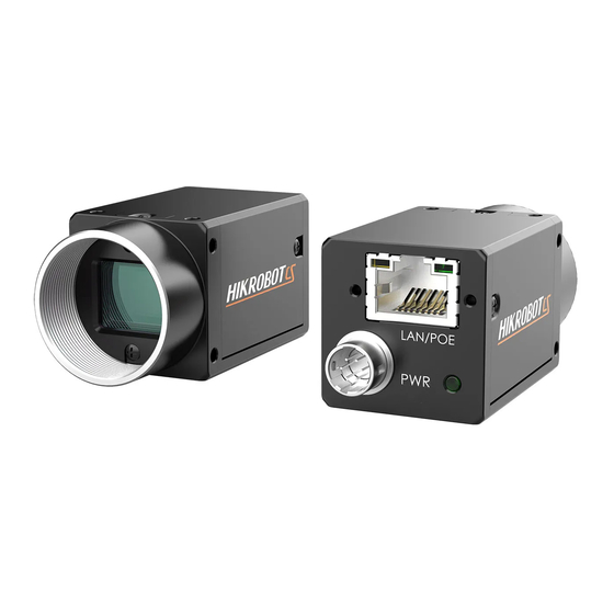
Page 12: Chapter 2 Appearance
It refers to the M2 screw hole for fixing the network Interface cable. GigE Interface It refers to the GigE interface for transmitting data. LED Indicator It indicates the device’s status. It provides power supply, input/output signal and serial Power and I/O Connector... -
Page 13: Chapter 3 I/O Connector And Indicator
Chapter 3 I/O Connector and Indicator 3.1 Power and I/O Connector All GigE line scan cameras have a 12-pin P10 connector, as shown below. However, the specific pin definitions differ by device models. Currently, two types of pin definitions are available. - Page 14 GigE Line Scan Camera User Manual Signal I/O Signal Source Description Line 2- Power supply ground IO_IN1_P Line 3+ Differential input IO 1+ IO_IN1_N Line 3- Differential input IO 1- Line 2+ Bi-directional IO IO_OUT0_P Line 1+ Differential output IO 0+...
-
Page 15: Indicator
GigE Line Scan Camera User Manual 3.2 Indicator The device’s indicator is used to indicate the operation status of the device. Note ● When the indicator is flashing rapidly, flashing slowly, or flashing very slowly, its unlit interval is 0.2 sec, 1 sec, and 2 sec respectively. -
Page 16: Chapter 4 Installation
Steps 1. Fix the device to the installation position. 2. Install the lens to the device. 3. Use a proper network cable to connect device with a GigE switch or a network interface card. 4. Select a power supply method: ●... -
Page 17: Chapter 5 Device Connection
GigE Line Scan Camera User Manual Chapter 5 Device Connection Device connection to the client software is required for device’s configurations and remote operations. This section introduces how to install the client software, connect the device to the client software, etc. -
Page 18: Set Pc Environment
GigE Line Scan Camera User Manual Figure 5-2 Default Settings 5. Keep default settings, and click Next. 6. Finish the installation according to the interface prompts. 5.2 Set PC Environment To ensure stable client running and data transmission, you are recommended to set PC environment. -
Page 19: Set Pc Network
GigE Line Scan Camera User Manual Figure 5-3 Windows Defender Firewall 4. Click OK. 5.2.2 Set PC Network Steps Note For different Windows versions, the specific setting path and interface may differ. Please refer to the actual condition. 1. Go to PC network settings page: Start → Control Panel → Network and Internet →... - Page 20 Interrupt Moderation Rate to Extremum. 4. (Optional) Set NIC property via the MVS. 1) Right click the GigE, and click NIC Settings. Figure 5-5 Click NIC Settings 2) Enable Jumbo Frame, and set Receive Buffers and Transmit Buffers to 2048.
-
Page 21: Set Device Network
GigE Line Scan Camera User Manual 5.3 Set Device Network You can set and operate the device in the client software only when the device is in the same network segment with the PC where the client software is installed. -
Page 22: Chapter 6 Client Software Layout
GigE Line Scan Camera User Manual Chapter 6 Client Software Layout After connecting to the device, the client software can read the its attributes and display them. Figure 6-1 Main Window Note For specific main window of the client software, please refer to the actual one you got. - Page 23 GigE Line Scan Camera User Manual Name Description You can view and set features of the selected device, and Feature Panel perform operations such as importing, exporting, and saving features. Click in the device’s feature panel to unfold the specific parameters, and set them according to actual demands.
- Page 24 GigE Line Scan Camera User Manual Feature Name Description to let the device generate an event and transmit a related message to the PC. You can view and set the device’s chunk data control related Chunk Data Control parameters to generate supplementary image data and append it to images.
-
Page 25: Chapter 7 Image Acquisition
GigE Line Scan Camera User Manual Chapter 7 Image Acquisition 7.1 Set Line Rate Note The image compression function may differ by device models. Refer to section Set Image Compression Mode for details. Line rate refers to the image line number that is output by the device per second. The frame rate of the device is proportional to its line rate, and is inversely proportional to the image height, that is, Fps = Lps (line rate)/Height (image height). -
Page 26: Set Frame Timeout
GigE Line Scan Camera User Manual 3. View Reference Line Rate (Hz) if you enable the image compression function to set line rate for reference. Note If the line rate is smaller than Reference Line Rate (Hz), the device acquires images in stable way. -
Page 27: Set Line Discard Function
GigE Line Scan Camera User Manual Parameter Description timeout period, the SDK will output the image according to the actual height. When the number of lines output by the device reaches the configured image height (height parameter) within the frame Partial Image timeout period, and one frame of image will be output. -
Page 28: Set Acquisition Mode
GigE Line Scan Camera User Manual 7.4 Set Acquisition Mode The device supports two types of acquisition modes, including SingleFrame mode and Continuous mode. Go to Acquisition Control → Acquisition Mode, and select Continuous or SingleFrame as Acquisition Mode according to actual demands. -
Page 29: Set Trigger Source
Table 7-3 Trigger Source Description Parameter Value Trigger Source Description The software sends trigger signal to the device via GigE interface to acquire images. Software Trigger Software Note The software trigger is available only when frame trigger is enabled. - Page 30 Set and Execute Software Trigger In software trigger, the software sends trigger signal to the device via GigE interface to acquire images. Steps 1. Go to Acquisition Control → Trigger Selector, and select Frame Burst Start as Trigger Selector.
- Page 31 GigE Line Scan Camera User Manual Figure 7-6 Set and Execute Hardware Trigger When selecting bi-directional configurable line as the hardware trigger source, you need to make sure that its line mode is input. Go to Digital IO Control, select specific line as Line Selector, and Input as Line Mode.
- Page 32 GigE Line Scan Camera User Manual Figure 7-8 Set Line Format Set and Execute Shaft Encoder Control If the device enables the line trigger, you can select Encoder Module Out as trigger source. At this time, the device will receive signal A and signal B with phase difference. After internal computing, the outputted signal can be used as device’s trigger signal.
- Page 33 GigE Line Scan Camera User Manual Follow steps below to set shaft encoder control. Steps 1. Click Encoder Control, and set Encoder Source A and Encoder Source B according to actual demands. 2. Set Encoder Trigger Mode. ● Any Direction means that both forward and backward direction will trigger.
- Page 34 GigE Line Scan Camera User Manual Figure 7-12 Process Logic of 4 Ticks Note For other device models, Encoder Trigger Frequency outputs 4 signals by default. 4. Set Encoder Counter Mode. ● Ignore Direction means that both forward and backward direction will count.
- Page 35 GigE Line Scan Camera User Manual 6. (Optional) Set Encoder Max Reverse Counter to avoid outputting images if the object moves backward accidently during measurement, and click Execute in Encoder Reverse Counter Reset to let the device to output images again.
- Page 36 GigE Line Scan Camera User Manual Figure 7-15 Set and Execute Frequency Converter Control Some device models support displaying trigger line rate. Note ● Parameters of trigger line rate and resulting trigger line rate may differ by device models. ● Make sure that line trigger is enabled and input source value of frequency converter control and trigger source value of acquisition control is the same before viewing trigger line rate.
-
Page 37: Set Trigger Related Parameters
GigE Line Scan Camera User Manual Set and Execute Free Trigger If the device enables the frame trigger or line trigger, you can select Anyway as trigger source to enable the free trigger. At this time, the device can receive signals of all trigger sources. - Page 38 GigE Line Scan Camera User Manual Table 7-4 Trigger Source and Trigger Related Parameters Trigger Source Frequency Software Hardware Free Converter Trigger Trigger Trigger Control Trigger Parameters Acquisition Burst Frame √ √ √ √ Count Trigger Activation × √ √...
- Page 39 GigE Line Scan Camera User Manual Set Acquisition Burst Frame Count If the device enables the frame trigger, you can set the acquisition burst frame count. Go to Acquisition Control → Acquisition Burst Frame Count, and enter Acquisition Burst Frame Count according to actual demands.
- Page 40 GigE Line Scan Camera User Manual the device receives trigger signal and starts to acquire images. ● Level High: The level high of the trigger signal is valid. As long as the trigger signal is in level high, the device is in image acquisition status.
- Page 41 GigE Line Scan Camera User Manual Set Trigger Activation in Line Trigger In the line trigger mode, the trigger activation is related with Exposure Mode. ● When Timed is selected as Exposure Mode, you can select Rising Edge or Falling Edge as Trigger Activation, and Exposure Auto and Exposure Time determine the exposure time.
- Page 42 GigE Line Scan Camera User Manual Figure 7-24 Set Trigger Delay under Line Trigger Figure 7-25 Sequence Diagram of Trigger Delay Note The sequence diagram above uses rising edge as trigger activation. Set Frame/Line Trigger Cache Note ● The frame/line trigger cache function may differ by device models.
- Page 43 GigE Line Scan Camera User Manual Figure 7-26 Set Trigger Cache in Frame Trigger If the device receives the 1st trigger signal first, and the device receives the 2nd trigger signal during processing the 1st trigger signal. ● Disable Trigger Cache Enable: the 2nd trigger signal will be filtered without processing.
- Page 44 GigE Line Scan Camera User Manual If the 1st frame image’s exposure time of the 2nd trigger signal is earlier than the device’s last frame creation time of the 1st trigger signal, and then the device will delay this exposure time. Thus making sure this exposure time is not earlier than the device’s last frame creation time of the 1st trigger signal.
- Page 45 GigE Line Scan Camera User Manual Set Trigger Debouncer The trigger debouncer function allows the device to filter out unwanted short external trigger signal that is input to the device. Go to Digital IO Control → Line Debouncer Time, and enter Line Debouncer Time according to actual demands.
-
Page 46: Chapter 8 Trigger Output
GigE Line Scan Camera User Manual Chapter 8 Trigger Output 8.1 Select Output Signal Note The selectable output signal line may differ by device models. The device has multiple differential output lines or bi-directional configurable lines. The method of setting bi-directional configurable line as output line as follows: Steps 1. -
Page 47: Set Output Signal
GigE Line Scan Camera User Manual 8.2 Set Output Signal The output signal of the device is switch signal that can be used to control external devices such as light source, PLC, etc. There are two ways to set output signal, including line inverter and strobe signal. - Page 48 GigE Line Scan Camera User Manual Figure 8-3 Select Frame Mode as Strobe Source Selector If you need to let the device output signals when event sources occur that are corresponding to each line image, follow steps below to set it.
- Page 49 GigE Line Scan Camera User Manual After selecting a specific line source, an event information will be generated, and the device will output a Strobe signal at the same time. The supported line sources are as follows: Note The specific line sources may differ by device models.
- Page 50 GigE Line Scan Camera User Manual When Counter Active is selected as Line Source, you can go to Counter and Timer Control and set specific parameters according to actual demands. Table 8-2 Description of Counter and Timer Control Parameter Read/Write...
- Page 51 GigE Line Scan Camera User Manual Figure 8-6 Timer Active Parameter Figure 8-7 Sequence Diagram of Timer Active When selecting Line Mode as Strobe Source Selector, you can also set duration, delay and pre delay for outputted signal. Note ● For some device models, in frame mode, you can set duration, delay and pre delay for outputted signal.
- Page 52 GigE Line Scan Camera User Manual Note ● When the Strobe Line Duration value is 0, the strobe duration is equal to the exposure time. ● When the Strobe Line Duration value is not 0, the strobe duration is equal to Strobe Line Duration value.
- Page 53 GigE Line Scan Camera User Manual Set Strobe Line Pre Delay The device also supports the function of strobe line pre delay, which means that the strobe signal takes effect early than exposure. This function is applied to the external devices that have slow response speed.
-
Page 54: Chapter 9 I/O Electrical Features And Wiring
GigE Line Scan Camera User Manual Chapter 9 I/O Electrical Features and Wiring 9.1 I/O Introduction There are two types of I/O signals in accordance with pin definitions. ● The first type: Two differential input signals (Line 0/3), two differential output signals (Line 1/4), and one bi-directional configurable signal (Line 2). - Page 55 GigE Line Scan Camera User Manual device’s ground signal with external ground signal if the differential input adopts RS-422 standard signal. RS-422 standard defines the connection of the bus structure, and the inputs of several devices can be connected to the RS-422. Up to 10 devices can be connected at the same time, of which only one device is the main dispenser and other devices are receivers.
-
Page 56: Differential Output Circuit
GigE Line Scan Camera User Manual 9.2.2 Differential Output Circuit The internal circuit of differential output signal in I/O signals is shown below. Figure 9-2 Internal Circuit of Differential Output The RS-422 standard and RS-644 standard are applied to the differential output. - Page 57 GigE Line Scan Camera User Manual Figure 9-3 Bi-Direction I/O Circuit Configure to Input Signal Logic 0 input level: 0 VDC to 0.5 VDC (GPIO2 pin). Logic 1 input level: 1.5 VDC to 30 VDC (GPIO2 pin). With the condition of 100 Ω and 5 VDC, the logic level and electrical feature of configuring GPIO2 as input are shown below.
- Page 58 GigE Line Scan Camera User Manual Table 9-2 Electrical Feature of Line 2 Input Parameter Name Parameter Symbol Value Input Rising Time 0.06 μs Input Falling Time 0.016 μs Input Rising Delay < 1 μs Input Falling Delay < 1 μs...
-
Page 59: Input Signal Wiring
● Make sure that the hardware trigger signals have been configured as input signal. ● Here we take one type of GigE line scan cameras as an example to introduce the input signal wiring. The appearance here is for reference only. - Page 60 GigE Line Scan Camera User Manual Camera Power Signal Source Power Differential Differential Input Positive Signal OUT A Source Differential Input Negative OUT Ã Signal Source Power Ground Camera Power Ground Camera GND Signal Source GND Figure 9-6 5 V Differential Signal Source Outputs Differential Signal ●...
- Page 61 GigE Line Scan Camera User Manual Signal Source Power Camera Power Differential Input Positive Differential OUT A Signal Source Hang Differential Input Negative Signal Ground ● Signal Source Power Ground Camera Power Ground Camera GND Signal Source GND Figure 9-8 Differential Signal Source Outputs Single-Ended Signal ●...
- Page 62 GigE Line Scan Camera User Manual ● When the NPN single-ended signal source provides signal, and the device’s differential input is used as single-ended input. The VCC of NPN single-ended signal source is 5 V, 12 V or 24 V.
-
Page 63: Second Type Of Input Signal Wiring
GigE Line Scan Camera User Manual 9.3.2 Second Type of Input Signal Wiring ● The differential signal source provides trigger signals. Signal Source Power Camera Power LINE*P OUT A Differential Signal LINE*N OUT Ã Source Signal Source Power Ground Camera Power Ground ●... -
Page 64: Output Signal Wiring
● The wiring may differ by I/O signals used as differential output or single-ended output. ● Here we take one type of GigE line scan cameras as an example to introduce the output signal wiring. The appearance here is for reference only. - Page 65 GigE Line Scan Camera User Manual ● When I/O signals are used as differential output, the wiring is shown below. Camera Power LINE*P OUT A Triggered Device LINE*N OUT Ã Power Ground of Trigger Device Camera Power Ground ● Figure 9-18 Differential Output Wiring ●...
-
Page 66: Chapter 10 Image Parameter
GigE Line Scan Camera User Manual Chapter 10 Image Parameter 10.1 View Resolution Note The device displays the image with max. resolution by default. Go to Image Format Control, and you can view resolution by reading Width Max and Height Max. Width Max stands for the max. pixels per inch in width direction, and Height Max stands for the max. -
Page 67: Set Image Reverse
GigE Line Scan Camera User Manual Figure 10-2 Set ROI 10.3 Set Image Reverse The device supports reversing images in a horizontal way. Go to Image Format Control, and enable Reverse X according to actual demands. Figure 10-3 Set Image Reverse... -
Page 68: Set Pixel Format
GigE Line Scan Camera User Manual 10.4 Set Pixel Format This function allows you to set the pixel format of the image data transmitted by the device. Go to Image Format Control → Pixel Format, and set Pixel Format according to actual demands. - Page 69 GigE Line Scan Camera User Manual The default output data format of mono device is Mono 8. The default output data format of color device is Bayer 8, and it can be converted into RGB format via pixel interpolation algorithm. RGB format can be converted into YUV format via the algorithm, and YUV format can be converted into Mono 8 format.
-
Page 70: Set Image Compression Mode
GigE Line Scan Camera User Manual 10.5 Set Image Compression Mode Note The function of the image compression is related with device models, firmware and pixel format, and the actual product you purchased should prevail. Without affecting image quality, this function allows the device to compress data before transmitting to the external devices, and lower the usage of bandwidth. - Page 71 GigE Line Scan Camera User Manual Test Pattern according to actual demands. Figure 10-12 Set Test Pattern The mono device offers 5 test patterns, including Mono Bar, Checkboard, Oblique Mono Bar, Gradual Mono Bar, and Test Image 1. The color device offers 7 test patterns, including Mono Bar, Checkboard, Oblique Mono Bar, Gradual Mono Bar, Vertical Color Bar, Horizontal Color Bar, and Test Image 1.
- Page 72 GigE Line Scan Camera User Manual Figure 10-15 Oblique Mono Bar Test Pattern Figure 10-16 Gradual Mono Bar Test Pattern Figure 10-17 Vertical Color Bar Test Pattern Figure 10-18 Horizontal Color Bar Test Pattern Figure 10-19 Test Image 1...
-
Page 73: Set Binning
GigE Line Scan Camera User Manual Note The pattern of the test image 1 may differ by device models. 10.7 Set Binning The purpose of setting binning is to enhance sensibility. With binning, multiple sensor pixels are combined as a single pixel to reduce resolution and improve image brightness. -
Page 74: Set Hdr
GigE Line Scan Camera User Manual When the exposure mode is set as Once or Continuous, the exposure time should be within the range of Auto Exposure Time Lower Limit (µ s) and Auto Exposure Time Upper Limit (µ s). -
Page 75: Set Gain
GigE Line Scan Camera User Manual Figure 10-22 Set HDR 10.10 Set Gain Note The gain function may differ by device models. The device has 2 types of gain, including the analog gain and digital gain. The analog gain is applied before the signal from the device sensor is converted into digital values, while digital gain is applied after the conversion. - Page 76 GigE Line Scan Camera User Manual Gain The device supports 3 types of gain mode, including Off, Once and Continuous. Click Analog Control → Gain Auto, and select Gain Auto according to actual demands. ● Off: The device adjusts gain according to the value configured by user in Gain.
-
Page 77: Set Digital Gain
GigE Line Scan Camera User Manual enter Gain (dB) directly. 10.10.2 Set Digital Gain Apart from analog gain, the device supports digital gain function. When analog gain reaching its upper limit and the image is still too dark, it is recommended to improve image brightness via digital gain. -
Page 78: Set Brightness
GigE Line Scan Camera User Manual Figure 10-27 Set Sensor Mode 10.12 Set Brightness The device brightness refers to the brightness when the device adjusts image under Once or Continuous exposure mode, or Once or Continuous gain mode. Note ● You should enable Once or Continuous exposure mode, or Once or Continuous gain mode first before setting brightness. -
Page 79: Set Black Level
GigE Line Scan Camera User Manual 10.13 Set Black Level Note The black level may differ by device models. The device supports black level function that allows you to change the overall brightness of an image by changing the gray values of the pixels by a specified amount. -
Page 80: Set Gamma Correction
GigE Line Scan Camera User Manual If there is still great difference between correction effect and actual color, it is recommended to correct white balance according to following steps. Steps Note ● Here we take Green as an example. For specific Balance Ratio Selector value, please refer to the actual condition. - Page 81 GigE Line Scan Camera User Manual Gamma=0.5 Gamma=1 Gamma=2 Gamma=4 Figure 10-30 Set Gamma Correction There are 2 types of Gamma correction, including User mode and sRGB mode. User Mode Steps 1. Go to Analog Control → Gamma Selector. 2. Select User as Gamma Selector.
-
Page 82: Set Aoi
GigE Line Scan Camera User Manual 3. Enable Gamma Enable to enable it. Figure 10-32 Set sRGB Mode 10.16 Set AOI Note ● The AOI function may differ by device models. ● AOI 1 is used when the device is in once or continuous exposure mode, and AOI 2 is used when the device is in once or continuous white balance mode. -
Page 83: Set Color Transformation Control
GigE Line Scan Camera User Manual 10.17 Set Color Transformation Control Note ● The function of color transformation control is only available for color devices. ● Currently, RGB to RGB is available for Color Transformation Selector only. ● Under Bayer pixel format, the MV-CL022-40GC device does not support color transformation control function. -
Page 84: Set Hue
GigE Line Scan Camera User Manual Note The parameter of CCM enable may differ by device models. 2. Enable Color Transformation Enable, and select Color Transformation Value Selector. 3. Set Hue and Saturation to adjust Color Transformation Value. Figure 10-35 Method 2 10.18 Set Hue... -
Page 85: Set Saturation
GigE Line Scan Camera User Manual Figure 10-36 Set Hue 10.19 Set Saturation Note ● The saturation function is only available for color devices. ● Only the pixel format is YUV, RGB or BGR, the MV-CL022-40GC device supports saturation function. -
Page 86: Set Color Adjustment
GigE Line Scan Camera User Manual Figure 10-37 Set Saturation 10.20 Set Color Adjustment Note ● The color adjustment function may differ by device models. ● In Bayer and Mono pixel formats, color devices do not support this function. The color adjustment function allows you to select different color areas in the image to set customized hue and saturation value. -
Page 87: Set Lut
GigE Line Scan Camera User Manual Figure 10-39 Set Color Adjustment 10.21 Set LUT A Look-Up Table (LUT) is a customizable grayscale-mapping table. You can stretch, amplify the grayscale range that interests you. The mapping can be linear or customized curve. -
Page 88: Set Shading Correction
GigE Line Scan Camera User Manual 10.22 Set Shading Correction Note The flat field correction function and specific setting method may differ by device models. The flat field correction (FFC) includes PRNUC correction and FPNC correction, and they are used to improve the image uniformity that may be impacted by the sensor, light sources, external conditions, etc. -
Page 89: Set Prnuc Correction
GigE Line Scan Camera User Manual 10.22.2 Set PRNUC Correction Note The PRNUC correction function and specific setting method may differ by device models. The device supports PRNUC (Photo-response Non-Uniformity Correction) function that eliminates vertical line on the images. Two correction methods are available, including global correction and ROI correction. - Page 90 GigE Line Scan Camera User Manual Figure 10-44 Set Shading Correction For MV-CL022-40GC device, follow steps below to operate: Steps 1. Click Shading Correction, and set PRNUC target related parameters according to actual demands. ● Select Off as PRNUC Target Enable if you want to use the device’s auto correction standard.
- Page 91 GigE Line Scan Camera User Manual ● Disable PRNUC Target Enable if you want to use the device’s auto correction standard. At this time, the device compares and corrects the average R/G/B component value of each column with the average R/G/B component value of the entire image.
-
Page 92: Set Space Correction
GigE Line Scan Camera User Manual 10.23 Set Space Correction Note The space correction function may differ by device models. The space correction (SC) includes line rate deviation correction and parallax deviation correction, and they are used to reduce image details deviation caused by line rate deviation or pixel deviation. -
Page 93: Set Pixel Shift And Parallax Direction
GigE Line Scan Camera User Manual Figure 10-48 Set Line Rate Ratio 10.23.2 Set Pixel Shift and Parallax Direction When pixel deviation occurs, images of mono devices are vague and images of color devices are dispersive. If you find the image’s edge has pixel deviation via observation, follow steps below to alleviate it. - Page 94 GigE Line Scan Camera User Manual Normal Image Device Type Abnormal Image Color Device Steps 1. Set Off as Parallax Direction if the image’s edge does not have pixel deviation. 2. Set Parallax Direction according to actual conditions if the image’s edge has pixel deviation.
-
Page 95: Chapter 11 Other Functions
GigE Line Scan Camera User Manual Chapter 11 Other Functions 11.1 Device Control Note The specific device control parameters may differ by device models. In Device Control, you can view device information, edit device name, reset device, etc. The specific parameters in Device Control are shown below. - Page 96 GigE Line Scan Camera User Manual Parameter Read/Write Description Device Connection Speed It indicates the speed of transmission of the Read only (Mbps) specified connection. Device Link Selector Read and It selects which Link of the device to control write...
-
Page 97: Embed Information Into Image
GigE Line Scan Camera User Manual Parameter Read/Write Description write Execute to find the currently operating device. Device Max Throughput Read only It is max. bandwidth of the data that can be (Kbps) streamed out of the device. Device PJ Number Read Only It is the device’s project number. - Page 98 GigE Line Scan Camera User Manual Image Embedding Byte Data Format Information reserved. Width Ranges from 0 to 2 Height Ranges from 0 to 2 Offset X Ranges from 0 to 2 Offset Y Ranges from 0 to 2 Pixel Format...
- Page 99 GigE Line Scan Camera User Manual Figure 11-2 Select Embedded Image Info Selector 2. Enable Frame Spec Info to add watermark into images. Figure 11-3 Enable Frame Spec Info 3. (Optional) Repeat steps above to add multiple watermarks. 4. Click on the control toolbar of the client software to view specific watermark information.
-
Page 100: Tdi Function
GigE Line Scan Camera User Manual 2. Select Chunk Selector according to actual demands. Figure 11-5 Select Chunk Selector 3. Enable Chunk Enable to embed information into the image. Figure 11-6 Chunk Enable 4. (Optional) Repeat steps above to add multiple Chunk information types. -
Page 101: Scan Direction
GigE Line Scan Camera User Manual TDI refers to Time Delay Integration, and it is a method of line scanning which provides dramatically increased responsivity compared to other video scanning methods. It permits much greater scanning speeds in low light, or allows reduced lighting levels (and costs) at conventional speeds. - Page 102 GigE Line Scan Camera User Manual The scan direction function is used to change the scan direction of the sensor used on measured objects. Go to Image Format Control → Reverse Scan Direction to enable Reverse Scan Direction according to actual demands, and observe the image effect at the same time.
-
Page 103: Set Action Command
Note ● The action command function may differ by device models. ● Only V3.1.0 and above version of MVS client software support GigE Vision action command. The action command allows you to execute actions on multiple devices at roughly the same time by using a single broadcast protocol message. - Page 104 GigE Line Scan Camera User Manual Figure 11-13 GigE Vision Action Command 6. Select Network Interfaces to set the subnet that the command to be sent to. 7. Enter Device Key, Group Key, and Group Mask. Table 11-3 Parameter Description...
-
Page 105: File Access Control
GigE Line Scan Camera User Manual command across the network. ● When the benchmark device receives the command, all devices will trigger certain actions simultaneously after the specified delay time. 11. (Optional) Enable Periodically Send to enable the client to send commands periodically, and enter Sending Interval according to actual demands. -
Page 106: Event Control
GigE Line Scan Camera User Manual Figure 11-15 Import or Export 3. Select a mfa file from local PC to import or select a saving path and enter file name to save and export. Note ● If User Set 1/2/3 is selected as device feature, you need to load the corresponding user set you selected to take effect. - Page 107 GigE Line Scan Camera User Manual Figure 11-16 Event Selector 2. Select Notification On as Event Notification to output event. Figure 11-17 Set Event Control 3. Right click the connected device and click Event Monitor. Figure 11-18 Event Monitor 4. Check Messaging Channel Event, and view the specific event after the device starts live...
-
Page 108: Transport Layer Control
GigE Line Scan Camera User Manual Figure 11-19 Event Monitor Window 11.8 Transport Layer Control You can go to Transport Layer Control to view the device’s payload size, GenCP version, etc. Note The specific parameters of transport layer control may differ by device models. - Page 109 GigE Line Scan Camera User Manual Parameter Read/Write Description GEV Device Mode Character Read only It is the character set in device’s register. It sets which physical network interface to GEV Interface Selector Read only be controlled. It is the MAC address of the network...
- Page 110 GigE Line Scan Camera User Manual Parameter Read/Write Description configuration scheme. It indicates the persistent subnet mask associated with the persistent IP address GEV Persistent Subnet Read and on this network interface. It is only used Mask write when the device boots with the persistent IP configuration scheme.
- Page 111 GigE Line Scan Camera User Manual Parameter Read/Write Description Read and It controls the destination IP address for GEV MCDA write the message channel. Read and It provides the transmission timeout value GEV MCTT (ms) write in milliseconds. It controls the number of retransmissions...
-
Page 112: Transfer Control
GigE Line Scan Camera User Manual 11.9 Transfer Control You can go to Transfer Control to view the device’s transfer sources, transfer mode, queue information, etc. Note The specific parameters of transfer control may differ by device models. Table 11-5 Parameters of Transfer Control... -
Page 113: User Set Customization
GigE Line Scan Camera User Manual 11.10 User Set Customization This function allows you to save or load device settings. The device supports four sets of parameters, including one default set and three user sets, and the relation among four sets of parameters is shown below. -
Page 114: Load User Set
GigE Line Scan Camera User Manual Figure 11-21 Save User Set 11.10.2 Load User Set Note Loading user set is available only when the device is connected but without live view. Steps 1. Go to User Set Control, and select a user set in User Set Selector. -
Page 115: Set User Default
GigE Line Scan Camera User Manual 11.10.3 Set User Default You can also set default parameter by going to User Set Control, and select a user set in User Set Default. Note Here we take selecting User Set 1 as an example. -
Page 116: Set Multicast (Connected Status)
GigE Line Scan Camera User Manual Figure 11-24 Multicast Settings 2. Select Role, and enter the IP Address and Port. Note ● The available status device can use multicast function in Controller and Data Receiver mode or Controller mode. ● The IP address should be class D IP address, and the port ranges from 0 to 65535. -
Page 117: Update Firmware
GigE Line Scan Camera User Manual Figure 11-26 Multicast Settings 2. Enable the multicast function, and edit the IP Address and Port. Note ● The connected status device can use multicast function in Controller and Data Receiver mode only. ● The IP address should be class D IP address, and the port ranges from 0 to 65535. - Page 118 GigE Line Scan Camera User Manual 2. Select corresponding device type like GigE, USB, or Camera Link. 3. Check to select the device you want to update. 4. Click to select update files (.dav files) in the local PC. 5. Click Update to start updating.
-
Page 119: Chapter 12 Faq (Frequently Asked Question)
GigE Line Scan Camera User Manual Chapter 12 FAQ (Frequently Asked Question) 12.1 Why the client software cannot list devices? Reason ● The device is not powered on. ● Incorrect network cable connection. Solution Check the device’s power supply and network connection by observing the device’s indicator and network link indicator. -
Page 120: Why The Device Cannot Be Triggered Although The Live View Is Normal
● Enable the trigger mode and make sure that the selected trigger source matches with the corresponding I/O signal. ● Check if the input of trigger signal and wiring are correct or not. 12.5 Why the network changes from GigE Ethernet to Fast Ethernet? Reason The network cable may be damaged. -
Page 121: Appendix A Device Parameter Index
GigE Line Scan Camera User Manual Appendix A Device Parameter Index Table Appendix A-1 Device Parameter Index Attribute Parameters Section Device Type Device Scan Type Device Vendor Name Device Model Name Device Manufacturer Info. Device Version Device Firmware Version Device Serial Number... - Page 122 GigE Line Scan Camera User Manual Attribute Parameters Section Device Reset Device Temperature Selector Device Temperature Find Me Device Max Throughput (Kbps) Device PJ Number HB Abnormal Monitor HB Version Width Max Section View Resolution Height Max Region Selector Region Destination...
- Page 123 GigE Line Scan Camera User Manual Attribute Parameters Section Acquisition Mode Section Set Acquisition Mode Acquisition Stop Acquisition Burst Frame Count Acquisition Line Rate (Hz) Acquisition Line Rate Control Enable Section Set Line Rate Resulting Line Rate (Hz) Resulting Frame Rate (Fps)
- Page 124 GigE Line Scan Camera User Manual Attribute Parameters Section Gain Auto Auto Gain Lower Limit Auto Gain Upper Limit Digital Shift Section Set Digital Gain Digital Shift Enable Brightness Section Set Brightness Black Level Section Set Black Level Black Level Enable...
- Page 125 GigE Line Scan Camera User Manual Attribute Parameters Section Saturation Enable Color Adjustment Enable Color Adjustment Selector Section Set Color Adjustment Color Adjustment Hue Color Adjustment Saturation LUT Selector LUT Enable LUT Control LUT Index Section Set LUT LUT Value...
- Page 126 GigE Line Scan Camera User Manual Attribute Parameters Section FPNC Enable PRNUC Enable PRNUC ROI Enable PRNUC Width PRNUC Offset X FPNC User Enable FPNC User Selector PRNUC User Enable PRNUC User Selector PRNUC Target Enable PRNUC Target PRNUC Target R...
- Page 127 GigE Line Scan Camera User Manual Attribute Parameters Section Strobe Line Pre Delay Action Unconditional Mode Action Device Key Action Queue Size Section Set Action Action Control Command Action Selector Action Group Mask Action Group Key Counter Selector Counter Event Source...
- Page 128 GigE Line Scan Camera User Manual Attribute Parameters Section GEV Device Mode Character Set GEV Interface Selector GEV MAC Address GEV Supported Option Selector GEV Supported Option GEV Current IP Configuration LLA GEV Current IP Configuration DHCP GEV Current IP Configuration Persistent...
- Page 129 GigE Line Scan Camera User Manual Attribute Parameters Section GEV MCP Host Port GEV MCDA GEV MCTT(ms) GEV MCRC GEV MCSP GEV Stream Channel Selector GEV SCP Interface Index GEV SCP Host Port GEV SCP Direction GEV SCPS Fire Test Packet...
- Page 130 GigE Line Scan Camera User Manual...
-
Page 131: Appendix B Revision History
GigE Line Scan Camera User Manual Appendix B Revision History Table Appendix B-1 Revision History Version Document No. Revision Date Revision Details ● Modify section Appearance. ● Modify section I/O Connector and Indicator ● Modify section Client Software Layout. ● Add section Set Frame Timeout. - Page 132 GigE Line Scan Camera User Manual Version Document No. Revision Date Revision Details ● Modify section Enable Strobe Signal. ● Add section I/O Introduction. ● Modify section I/O Electrical Feature. ● Modify section Input Wiring. ● Modify section Set Test Pattern.
- Page 133 UD28749B...
Need help?
Do you have a question about the GigE and is the answer not in the manual?
Questions and answers