Table of Contents
Advertisement
Quick Links
Advertisement
Table of Contents

Related Manuals for HikRobot CameraLink Area Scan Camera


Summary of Contents for HikRobot CameraLink Area Scan Camera
- Page 1 CameraLink Area Scan Camera User Manual...
- Page 2 WITHOUT LIMITATION, MERCHANTABILITY, SATISFACTORY QUALITY, OR FITNESS FOR A PARTICULAR PURPOSE. THE USE OF THE PRODUCT BY YOU IS AT YOUR OWN RISK. IN NO EVENT WILL HIKROBOT BE LIABLE TO YOU FOR ANY SPECIAL, CONSEQUENTIAL, INCIDENTAL, OR INDIRECT DAMAGES,...
- Page 3 TO ANY NUCLEAR EXPLOSIVE OR UNSAFE NUCLEAR FUEL-CYCLE, OR IN SUPPORT OF HUMAN RIGHTS ABUSES. THE PERFORMANCE DATA IN THIS PUBLICATION IS BASED ON HIKROBOT’S INTERNAL RESEARCH/EVALUATION. ACTUAL DATA MAY VARY DEPENDING ON SPECIFIC CONFIGURATIONS AND OPERATING CONDITIONS AND HIKROBOT SHALL NOT BEAR THE CONSEQUENCES ARISING THEREFROM.
- Page 4 Indicates a hazard with a high level of risk, which if not avoided, will result in death or serious injury. Available Model This manual is applicable to the CameraLink Area Scan Camera.
- Page 5 CameraLink Area Scan Camera·User Manual Safety Instructions These instructions are intended to ensure that the user can use the device correctly to avoid danger or property loss. Laws and Regulations The device should be used in compliance with local laws, electrical safety regulations, and fire prevention regulations.
- Page 6 CameraLink Area Scan Camera·User Manual It is suggested to wear anti-static suit to prevent damage to the equipment caused by static electricity. When installing or maintaining the device, wear anti-static wristband or anti-static gloves. Make sure that the wristband is tightly attached to the skin and is reliably grounded.
- Page 7 CameraLink Area Scan Camera·User Manual E-mail: tech_support@hikrobotics.com Website: en.hikrobotics.com...
-
Page 8: Table Of Contents
CameraLink Area Scan Camera·User Manual Table of Contents Chapter 1 Overview ........................1 1.1 Appearance ........................1 1.2 Power and I/O Interface ....................3 1.3 Indicator Description...................... 6 Chapter 2 Camera Installation ......................7 2.1 Accessory ........................7 2.2 Install Camera ........................ 7 Chapter 3 Client Installation and Setting .................. - Page 9 CameraLink Area Scan Camera·User Manual 5.4.3 Set Trigger Cache Enable ..................27 5.4.4 Set Trigger Activation ..................28 5.4.5 Set Trigger Debouncer ..................29 Chapter 6 I/O Output........................31 6.1 Select Output Signal ..................... 31 6.2 Set Output Signal ......................31 6.2.1 Enable Level Inverter ...................
- Page 10 CameraLink Area Scan Camera·User Manual 8.16 Set AOI ........................61 8.17 Set LUT ........................62 8.18 Set Shading Correction ....................62 Chapter 9 Other Functions......................64 9.1 Device Control ......................64 9.2 Set Fan ......................... 65 9.3 Save and Load User Set ....................66 9.4 Set Transport Layer Control ..................
-
Page 11: Chapter 1 Overview
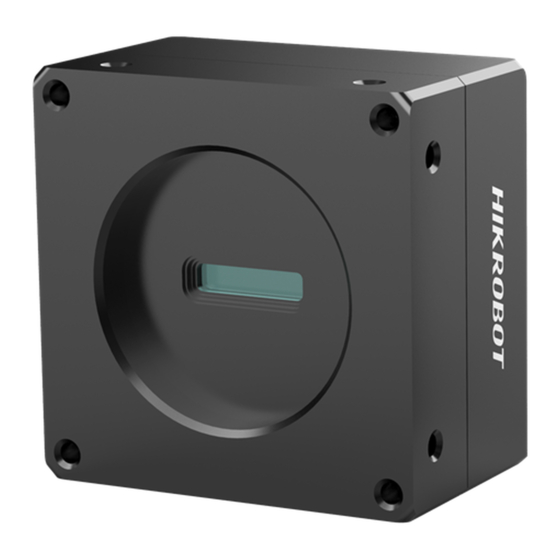
CameraLink Area Scan Camera·User Manual Chapter 1 Overview 1.1 Appearance The camera has different appearances with varied models, as shown below. Type I is C-mount camera, type II is M58-mount camera with fan, type III is F-mount camera with fan, type IV is F-mount camera with TEC, and type V is M58-mount camera with TEC. - Page 12 CameraLink Area Scan Camera·User Manual Figure 1-4 Appearance (Type IV) Figure 1-5 Appearance (Type V) Table 1-1 Interface Description Interface Description Lens mount It is used to install lens. For specific lens type, please refer to the camera’s specification for details.
-
Page 13: Power And I/O Interface
CameraLink Area Scan Camera·User Manual For other types, they have a 12-pin power and I/O interface. LED indicator It shows the camera’s status. It is used to cool the camera. 1.2 Power and I/O Interface For different models of cameras, they have varied power and I/O interfaces. For type I, it has a 6-pin power and I/O interface, and its pin definition is shown in Table 1-2. - Page 14 CameraLink Area Scan Camera·User Manual Table 1-3 Pin Definition (Type II and Type III) Illustration Signal I/O Signal Description Color Source Line 2 signal Camera power Black ground supply ground DC_PWR Camera power supply TX485+ TX485+ White/Blue TX485- TX485- White/Green...
- Page 15 CameraLink Area Scan Camera·User Manual Table 1-4 Pin Definition (Type IV and Type V) Illustration Signal I/O Signal Description Color Source Camera Black power supply ground DC_PWR Camera power supply DC_PWR_TEC -- TEC power White/Blue supply DC_PWR_TEC TEC power White/Green...
-
Page 16: Indicator Description
CameraLink Area Scan Camera·User Manual The cable color here refers to the color of cable supplied. If cable of other manufacturers is used, the cable color may differ, and the actual cable you purchased shall prevail. 1.3 Indicator Description The indicator has different status, and please refer to the following table for the details. -
Page 17: Chapter 2 Camera Installation
CameraLink Area Scan Camera·User Manual Chapter 2 Camera Installation 2.1 Accessory You need to prepare following accessories before installation. Table 2-1 Recommended Accessories Name Quantity Description Camera body ×1 The camera mentioned in this user manual. CameraLink frame grabber that you need to Frame grabber ×1... - Page 18 CameraLink Area Scan Camera·User Manual Steps: 1. Fix the camera to the installation position. 2. Install the lens to the camera body. 3. Connect the camera to a frame grabber via CameraLink cable. 4. Connect the camera to a 6-pin or 12-pin power and I/O cable.
-
Page 19: Chapter 3 Client Installation And Setting
CameraLink Area Scan Camera·User Manual Chapter 3 Client Installation and Setting 3.1 Frame Grabber Software Operation 3.1.1 Install Frame Grabber Software Purpose: The frame grabber software can connect camera, acquire image data, set parameters, etc. Steps: 1. Obtain the frame grabber software installation package and driver package from frame grabber supplier. -
Page 20: Mvs Client Operation
CameraLink Area Scan Camera·User Manual Frame Grabber Parameters Camera Parameters Pixel Clock Frequency Pixel Clock Cameralink config Configuration Mode Taps Tap Number Tap Configuration Tap Mode The parameter names may vary from different frame grabbers and are subject to the frame grabber you purchased. -
Page 21: Set Mvs Client
CameraLink Area Scan Camera·User Manual Figure 3-1 Installation Interface 3. Click Start Setup. 3.2.2 Set MVS Client Steps: 1. After powering on the camera, double-click the MVS client to open it. 2. Click to find the camera in device list, as shown below. -
Page 22: Main Window
CameraLink Area Scan Camera·User Manual 3.2.3 Main Window After connecting to the camera, the MVS client can read the camera attributes and display them in tree format. The main window and the description of the client are shown in Figure 3-3 and Table 3-3 respectively. -
Page 23: Feature Tree
CameraLink Area Scan Camera·User Manual Area Name Description Display Window View the live video of the selected camera. View and configure features of the selected camera, and perform other operations such as importing, Feature Panel exporting, and saving features. You can refer to the MVS User Manual for detailed MVS operations by clicking Help > User Manual in the MVS software. -
Page 24: Transport Layer Control
CameraLink Area Scan Camera·User Manual Table 3-4 Attribute Description Attribute Description You can view camera information, edit its name and Device Control reset the camera. You can view and set the camera’s resolution, image Image Format reverse function, pixel format, region of interest, test Control pattern, etc. -
Page 25: Serial Port Tool
CameraLink Area Scan Camera·User Manual Figure 3-5 Device Tap Geometry For cameras of different models, the mode that the camera supports may differ. Pease refer to the specification of the camera for detailed information. 3.3 Serial Port Tool Purpose: Apart from the MVS client and frame grabber software, the serial port tool can also be used to detect camera status, read and set camera parameters. - Page 26 CameraLink Area Scan Camera·User Manual The camera parameters can be set via the MVS client, frame grabber or serial port tool, but you cannot use them at same time. The default value of the camera’s baud rate is 9600 bps.
-
Page 27: Chapter 4 Camera Feature
CameraLink Area Scan Camera·User Manual Chapter 4 Camera Feature 4.1 Global Shutter The camera mentioned in this user manual is a global shutter camera. For camera that supports global shutter, its exposure starts and ends in each line simultaneously. After the exposure, data readout starts line by line. - Page 28 CameraLink Area Scan Camera·User Manual Exposure 1 Exposure 2 Exposure 3 Sensor exposure Frame 1 Frame 2 Readout Readout Figure 4-2 Internal Trigger Overlap Exposure Overlap Exposure under External Trigger Mode Figure 4-3 External Trigger Overlap Exposure...
-
Page 29: Chapter 5 Image Acquisition
CameraLink Area Scan Camera·User Manual Chapter 5 Image Acquisition 5.1 Set Frame Rate Frame rate refers to the image number that is acquired by the camera per second. The higher frame rate, and shorter time used for image acquisition will be. The following 4 factors determines the camera’s frame rate in real-time. -
Page 30: Set Trigger Mode
CameraLink Area Scan Camera·User Manual Figure 5-2 Check Resulting Frame Rate 5.2 Set Trigger Mode The camera has 2 types of trigger mode, including internal trigger mode and external trigger mode. The trigger mode principle and parameter setting are shown below. -
Page 31: External Trigger Mode
CameraLink Area Scan Camera·User Manual Off refers to the internal trigger mode, and On refers to the external trigger mode. 5.3 External Trigger Mode 5.3.1 Set External Trigger Source There are 4 types of external trigger sources, including software trigger, hardware trigger, counter trigger and frame grabber trigger. -
Page 32: Set Software Trigger
CameraLink Area Scan Camera·User Manual Figure 5-4 Set External Trigger Source These 4 external trigger sources are valid only when the Trigger Mode is On. For type IV camera and type V camera, there is no configurable Line 2. -
Page 33: Set Hardware Trigger
CameraLink Area Scan Camera·User Manual 5.3.3 Set Hardware Trigger The camera has 1 Opto-isolated input (Line 0), and 1 bi-directional I/O (Line 2) that can be configured as input signal, as shown below. Steps: 1. Click Digital IO Control. 2. Select Line 2 as Line Selector, and Input as Line Mode. - Page 34 CameraLink Area Scan Camera·User Manual Figure 5-8 Set Counter Trigger When using counter as trigger source, you need to set relevant parameters under Counter And Timer Control. For specific parameter function and setting, please refer to the following table. Table 5-3 Description of Counter And Timer Control...
-
Page 35: Set Frame Grabber Trigger
CameraLink Area Scan Camera·User Manual Figure 5-9 Counter Trigger Parameters 5.3.5 Set Frame Grabber Trigger You can set frame grabber trigger as shown below. Steps: 1. Click Acquisition Control > Trigger Selector. 2. Select Frame Burst Start as Trigger Selector, and On as Trigger Mode. -
Page 36: Trigger Related Parameters
CameraLink Area Scan Camera·User Manual 5.4 Trigger Related Parameters Under external trigger mode, you can set burst frame count, trigger delay, trigger cache enable, trigger activation and trigger debouncer. Different trigger sources can set various trigger parameters, and their relation is shown below. -
Page 37: Set Trigger Delay
CameraLink Area Scan Camera·User Manual Burst Count = 4 Trigger Sensor exposure Figure 5-12 Sequence Diagram of Burst Frame Count 5.4.2 Set Trigger Delay From camera receiving signal and responding, this period is trigger delay. Its sequence diagram is shown below. -
Page 38: Set Trigger Activation
CameraLink Area Scan Camera·User Manual Steps: 1. Click Acquisition Control > Trigger Cache Enable. 2. Enable Trigger Cache Enable. Figure 5-15 Enable Trigger Cache Enable If the camera receives the 1st trigger signal first, and the camera receives the 2nd trigger signal during processing the 1st trigger signal. -
Page 39: Set Trigger Debouncer
CameraLink Area Scan Camera·User Manual Trigger Activation Parameter Parameter Value Principle the trigger signal. Acquisition Control > Falling Edge refers to the falling Falling edge Falling Edge Trigger Activation edge of the trigger signal is valid, that is camera exposure... - Page 40 CameraLink Area Scan Camera·User Manual Trigger_in1 Trigger_in2 Trigger_in3 Before debounce Trigger_in2 Trigger_in3 After debounce Debouncer Time Debouncer Time Debouncer Time (t1>t2, trigger signal is ignored) (t3<t4, trigger signal outputs after delaying t3) (t5<t6, trigger signal outputs after delaying t5) Figure 5-17 Trigger Debouncer Sequence Diagram You can set trigger debouncer as shown below.
-
Page 41: Chapter 6 I/O Output
CameraLink Area Scan Camera·User Manual Chapter 6 I/O Output 6.1 Select Output Signal The camera has 1 opto-isolated output (Line 1), and 1 bi-directional I/O (Line 2) that can be configured as output signal, as shown below. Steps: 1. Click Digital IO Control. -
Page 42: Enable Strobe Signal
CameraLink Area Scan Camera·User Manual The Line Inverter parameter is disabled by default. 6.2.2 Enable Strobe Signal The strobe signal is used to directly output I/O signal to external devices when camera’s event source occurs. You can enable strobe signal as shown below. - Page 43 CameraLink Area Scan Camera·User Manual Figure 6-4 Set Strobe Line Duration When the Strobe Line Duration value is 0, the strobe duration is equal to the exposure time. When the Strobe Line Duration value is not 0, the strobe duration is equal to Strobe Line Duration value.
- Page 44 CameraLink Area Scan Camera·User Manual Figure 6-5 Set Strobe Line Delay The sequence diagram of strobe line delay is shown below. Figure 6-6 Sequence Diagram of Strobe Line Delay Set Strobe Line Pre Delay The camera also supports the function of strobe line pre delay, which means that the strobe signal takes effect early than exposure.
- Page 45 CameraLink Area Scan Camera·User Manual Figure 6-7 Set Strobe Line Pre Delay The sequence diagram of strobe line pre delay is shown below. Figure 6-8 Sequence Diagram of Strobe Line Pre Delay...
-
Page 46: Chapter 7 I/O Electrical Feature And Wiring
CameraLink Area Scan Camera·User Manual Chapter 7 I/O Electrical Feature and Wiring 7.1 I/O Electrical Feature 7.1.1 Line 0 Opto-isolated Input Circuit The Line 0 opto-isolated input circuit in camera I/O control is shown below. Figure 7-1 Line 0 Internal Circuit The maximum input current of Line 0 is 25 mA. -
Page 47: Line 1 Opto-Isolated Output Circuit
CameraLink Area Scan Camera·User Manual Parameter Name Parameter Symbol Value Input Rising Delay 1.8 μs to 4.6μs Input Falling Delay 16.8 μs to 22 μs Make sure the input voltage is not from 1 VDC to 1.5 VDC as the electric status between these two values are not stable. -
Page 48: Line 2 Bi-Direction I/O Circuit
CameraLink Area Scan Camera·User Manual Table 7-2 Output Electric Feature Parameter Name Parameter Symbol Value Output Logic Level Low 575 mV Output Logic Level High 3.3 V Output Rising Time 8.4 μs Output Falling Time 1.9 μs Output Rising Delay 15 μs to 60 μs... - Page 49 CameraLink Area Scan Camera·User Manual Type IV camera and type V camera do not have bi-direction I/O function. Line 2 Configured as Input With the condition of 100 Ω and 5 VDC, the logic level and electrical feature of configuring Line 2 as output are shown below.
- Page 50 CameraLink Area Scan Camera·User Manual Table 7-5 Parameter of Output Logic Level Low External Voltage External Resistance VL (GPIO2) 3.3 V 1 KΩ 160 mV 1 KΩ 220 mV 12 V 1 KΩ 460 mV 24 V 1 KΩ 860 mV 30 V 1 KΩ...
-
Page 51: I/O Wiring
CameraLink Area Scan Camera·User Manual Parameter Name Parameter Symbol Value Output Rising Delay 0 μs to 4μs Output Falling Delay < 1 μs 7.2 I/O Wiring The camera has different appearances and I/O interfaces with varied models. Here we take type II camera as an example to introduce I/O wiring. -
Page 52: Line 1 Wiring
CameraLink Area Scan Camera·User Manual Camera Power Device Power Supply Supply Signal Line NPN Device Opt-Iso in Device Power I/O Ground Ground Camera Power Ground GND of VCC GND of PWR Figure 7-9 Line 0 Connecting to NPN Device Switch If the VCC of switch is 24 VDC, and it is recommended to use 1 KΩ... -
Page 53: Line 2 Wiring
CameraLink Area Scan Camera·User Manual If the VCC of NPN device is 24 VDC, and it is recommended to use 1 KΩ to 4.7 KΩ pull-up resistor. If the VCC of NPN device is 12 VDC, and it is recommended to use 1 KΩ pull-up resistor. - Page 54 CameraLink Area Scan Camera·User Manual Camera Power Device Power Supply Supply Bi-direction NPN Device Signal Line Device Power Camera Ground Power Ground GND of PWR and VCC Figure 7-14 Line 2 Connecting to NPN Device as Input Switch If the VCC of switch is 24 VDC, and it is recommended to use 1 KΩ to 4.7 KΩ resistor to protect circuit.
- Page 55 CameraLink Area Scan Camera·User Manual NPN Device If the VCC of NPN device is 24 VDC, and it is recommended to use 1 KΩ to 4.7 KΩ pull-up resistor. If the VCC of NPN device is 12 VDC, and it is recommended to use 1 KΩ pull-up resistor.
-
Page 56: Chapter 8 Image Parameter
CameraLink Area Scan Camera·User Manual Chapter 8 Image Parameter 8.1 Check Resolution Steps: 1. Click Image Format Control. 2. Check Width Max and Height Max. Width Max stands for the max. pixels per inch in width direction and Height Max stands for the max. pixels per inch in height direction. -
Page 57: Set Image Reverse
CameraLink Area Scan Camera·User Manual Figure 8-2 Set ROI The Width value plus Offset X value should not be larger than Width Max parameter value, Height value plus Offset Y value should not be larger than Height Max parameter value ... -
Page 58: Set Pixel Format
CameraLink Area Scan Camera·User Manual Figure 8-3 Set Image Reverse Figure 8-4 Image Reverse Comparison For different models of camera, the image reverse function may be different, please refer to the actual one you got. 8.4 Set Pixel Format The camera supports many pixel formats. For specific pixel formats that the camera supports, please refer to the specifications of the camera. -
Page 59: Set Test Pattern
CameraLink Area Scan Camera·User Manual Table 8-1 Data Format of Different Pixel Formats Pixel Format Data Format Mono 8, Bayer 8 Mono 10/12, Bayer 10/12 RGB 8 You can set pixel format as shown below. Steps: 1. Click Image Format Control > Pixel Format. - Page 60 CameraLink Area Scan Camera·User Manual Figure 8-6 Set Test Pattern The camera offers 5 test patterns, including Mono Bar, Check board, Oblique Mono Bar, Gradual Mono Bar and Horizontal Color Bar, as shown below. Figure 8-7 Mono Bar Test Pattern...
- Page 61 CameraLink Area Scan Camera·User Manual Figure 8-9 Oblique Mono Bar Test Pattern Figure 8-10 Gradual Mono Bar Test Pattern Figure 8-11 Horizontal Color Bar Test Pattern For different models of camera, the test pattern may be different, please refer to the actual one...
-
Page 62: Set Binning
CameraLink Area Scan Camera·User Manual 8.6 Set Binning The purpose of setting binning is to enhance sensibility. With binning, multiple sensor pixels are combined as a single pixel to reduce resolution and improve image brightness. You can set binning as shown below. -
Page 63: Set Gain
CameraLink Area Scan Camera·User Manual Exposure Mode Parameter Parameter Value Principle Acquisition Control > Adjust the exposure time Once Once Exposure Auto automatically according to the image brightness. After adjusting, it will switch to Off Mode. Continuous Acquisition Control >... -
Page 64: Set Digital Gain
CameraLink Area Scan Camera·User Manual Table 8-3 Analog Gain Mode and Principle Analog Gain Mode Parameter Parameter Value Principle Analog Control > The camera adjusts analog Gain Auto gain according to the value configured by user in Gain. Once Analog Control >... -
Page 65: Set Brightness
CameraLink Area Scan Camera·User Manual 1. Click Analog Control and enable Digital Shift Enable. 2. Enter proper value in Digital Shift. Figure 8-15 Set Digital Gain The digital gain is disabled by default, and its range is from -6 dB to 6 dB. -
Page 66: Set Black Level
CameraLink Area Scan Camera·User Manual Figure 8-16 Set Brightness After setting brightness, the camera will automatically adjust exposure time to let image brightness reach target one. Under Once or Continuous exposure mode, or Once or Continuous gain, the higher the brightness value, the brighter the image will be. - Page 67 CameraLink Area Scan Camera·User Manual The white balance refers to the camera color adjustment depending on different light sources. Adjust the Gain Value of the image’s R channel and B channel to keep white regions white under different color temperatures. Ideally, the proportion of R channel, G channel and B channel in the white region is 1:1:1.
-
Page 68: Set Gamma Correction
CameraLink Area Scan Camera·User Manual 4. Take Green as correction standard, and manually adjust other two channels (R channel and B channel) to let these three channels have same value. Here we take Green as an example. For specific Balance Ratio Selector value, please refer to the actual condition. -
Page 69: Set Saturation
CameraLink Area Scan Camera·User Manual 3. Enable Gamma Enable. 4. Enter proper value in Gamma according to actual demands, and its range is from 1 to 4. Figure 8-19 Set User Mode You can set sRGB mode as shown below. -
Page 70: Set Sharpness
CameraLink Area Scan Camera·User Manual Figure 8-21 Set Saturation In the format of Bayer, the color camera does not have saturation function. 8.14 Set Sharpness The camera supports sharpness function that can adjust the sharpness level of the image edge, and this function is disabled by default. -
Page 71: Set Aoi
CameraLink Area Scan Camera·User Manual The Active Mode refers to active correction, which the device adjusts channel difference in real-time according to actual image. The Passive Mode refers to passive correction, which the device adjusts channel difference in real-time according to preset parameters. -
Page 72: Set Lut
CameraLink Area Scan Camera·User Manual 8.17 Set LUT A Look-Up Table (LUT) is a customized grayscale-mapping table. You can stretch, amplify the grayscale range that interests you. The mapping can be linear or customized curve. You can set LUT as shown below. - Page 73 CameraLink Area Scan Camera·User Manual 4. Enable NUFFC Enable. Figure 8-26 Set Shading Correction...
-
Page 74: Chapter 9 Other Functions
CameraLink Area Scan Camera·User Manual Chapter 9 Other Functions 9.1 Device Control In the Device Control interface, you can view device information, edit device name, reset device, etc. The specific parameters in Device Control interface are shown below. Table 9-1 Device Control Parameter Description... -
Page 75: Set Fan
CameraLink Area Scan Camera·User Manual Parameter Read/Write Description Device Command Read only It counts the timeout of command. Timeout Device Reset Write only Click Execute to reset the device. Device Clock Selector Read and write It selects device clock. Device Clock Frequency Read and write It is device’s pixel clock. -
Page 76: Save And Load User Set
CameraLink Area Scan Camera·User Manual When the camera’s temperature is higher than the threshold you set, fan starts to work. When the camera’s temperature is 5 °C (41 °F) lower than the threshold you set, fan stops working. Only type II camera and type III camera have fan. - Page 77 CameraLink Area Scan Camera·User Manual Load Parameters Steps: 1. Click User Set Control, and select a user set in User Set Selector. Here we take selecting User Set 1 as an example. 2. Click Execute in User Set Load to load parameters to the camera, as shown below.
-
Page 78: Set Transport Layer Control
CameraLink Area Scan Camera·User Manual 9.4 Set Transport Layer Control You can go to Transport Layer Control to view the camera’s load size, tap configuration mode, GenCP version, etc. The specific parameters in Transport Layer Control interface and output order of different taps are shown below. -
Page 79: Update Firmware
CameraLink Area Scan Camera·User Manual When Device Tap Geometry is Geometry_1X_2YE, the output order of tap is shown below. Vertical Figure 9-7 Geometry_1X_2YE When Device Tap Geometry is Geometry_1X2_2YE, the output order of tap is shown below. Vertical Figure 9-8 Geometry_1X2_2YE ... - Page 80 CameraLink Area Scan Camera·User Manual Steps: 1. Click Tool > Firmware Updater to open the update interface. 2. Click in CameraLink to search the camera. 3. Click to select the camera you want to update. 4. Click to select the update file in the local computer.
-
Page 81: Chapter 10 Trouble Shooting
CameraLink Area Scan Camera·User Manual Chapter 10 Trouble Shooting Table 10-1 Trouble Shooting Trouble Possible Reason Solution No camera found when The camera is not Check the camera’s power supply by running the MVS client started up normally. viewing the camera’s LED indicator. -
Page 82: Chapter 11 Revision History
CameraLink Area Scan Camera·User Manual Chapter 11 Revision History Table 11-1 Revision History Version No. Document No. Date Revision Details 1.0.0 UD12979B Jan. 9, 2019 Original version. Add different appearances of the 1.0.1 UD14755B May 18, 2019 camera. Delete acquisition mode. -
Page 83: Appendix A Camera Parameter Index
CameraLink Area Scan Camera·User Manual Appendix A Camera Parameter Index Table Appendix A-1 Camera Parameter Index Attribute Parameter Section Device Control Device Scan Type Section 9.1 Device Vendor Name Device Model Name Manufacturer Info Device Family Name Device Version Device Firmware Version... - Page 84 CameraLink Area Scan Camera·User Manual Region Selector Width Height Offset X Offset Y Reverse X Section 8.3 Reverse Y Pixel Format Section 8.4 Pixel Size Test Pattern Generator Selector Section 8.5 Test Pattern Binning Selector Section 8.6 Binning Horizontal Binning Vertical Acquisition Burst Frame Count Section 5.4...
- Page 85 CameraLink Area Scan Camera·User Manual Auto Exposure Time Lower Limit (µs) Auto Exposure Time Upper Limit (µs) Analog Control Gain Section 8.8.1 Gain Auto Auto Gain Lower Limit Auto Gain Upper Limit Digital Shift Section 8.8.2 Digital Shift Enable Brightness Section 8.9...
- Page 86 CameraLink Area Scan Camera·User Manual Auto Function AOI Usage Intensity Auto Function AOI Usage White Balance LUT Control LUT Selector Section 8.17 LUT Enable LUT Index LUT Value Shading Selector Section 8.18 Shading Correction Activate Shading NUFFC Enable Digital IO Line Selector Section 5.3.3...
- Page 87 CameraLink Area Scan Camera·User Manual Control Device Tap Geometry CI Configuration GenCP Version Major GenCP Version Minor Supported Baudrates User Set Current Section 9.3 User Set Control User Set Selector User Set Load User Set Save User Set Default...
-
Page 88: Appendix B Command List
CameraLink Area Scan Camera·User Manual Appendix B Command List The commands listed in the command list below are common ones only. For other commands, please contact technical support personnel via e-mail: tech_support@hikrobotics.com for detailed information. Table Appendix B-1 Command List... - Page 89 CameraLink Area Scan Camera·User Manual PixelFormat w PixelFormat n 0x01080001: Mono8 r PixelFormat 0x01100003: Mono10 0x01100005: Mono12 0x02180014: RGB 8 0x01080009: BayerRG8 0x0110000d: BayerRG10 0x01100011: BayerRG12 TestPattern w TestPattern n 0: off r TestPattern 11: MonoBar 12: HorizontalColorBar 13: Checkboard...
- Page 90 CameraLink Area Scan Camera·User Manual TriggerSource w TriggerSource+6 n 0: line0 r TriggerSource+6 1: line1 2: line2 4: Counter0 7: Software 9: CC1 11: CC2 12: CC3 13: CC4 TriggerActivation w TriggerActivation+6 n 0: RisingEdge r TriggerActivation+6 1: FallingEdge TriggerDelayAbsVal...
- Page 91 CameraLink Area Scan Camera·User Manual GammaAbsVal w GammaAbsVal n n = GammaAbsVal x 100 r GammaAbsVal + n1 0x10000: User 0x20000: sRGB GammaCtrl w GammaCtrl n 0: Disable r GammaCtrl 1: Enable SharpnessVal w SharpnessVal n 0 - 100 r SharpnessVal...
- Page 92 CameraLink Area Scan Camera·User Manual LineStrobe w LineStrobe n 0: Disable r LineStrobe bit1: line1 Enable bit2: line2 Enable bit4: line4 Enable LineDebouncerTime w LineDebouncerTime+n1 n2 r LineDebouncerTime+n1 0: set LineSelector to line0 1: set LineSelector to line1 2: set LineSelector to...
- Page 93 CameraLink Area Scan Camera·User Manual StrobeLineDelay w StrobeLineDelay+n1 n2 r StrobeLineDelay+n1 0: set LineSelector to line0 1: set LineSelector to line1 2: set LineSelector to line2 5: set LineSelector to 6: set LineSelector to 7: set LineSelector to 8: set LineSelector to...
- Page 94 CameraLink Area Scan Camera·User Manual UserSetDefaultSelector R/W w UserSetDefaultSelector n 0: default r UserSetDefaultSelector 1: userset1 2: userset2 3: userset3...
- Page 95 UD14755B...
Need help?
Do you have a question about the CameraLink Area Scan Camera and is the answer not in the manual?
Questions and answers