Table of Contents
Advertisement
Quick Links
FOREWORD
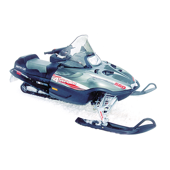
This Arctic Cat Service Manual contains service and maintenance information for the Model Year 2004 Arctic Cat 4-
Stroke Snowmobiles. The manual is designed to aid service personnel in service-oriented applications.
This manual is divided into sections. The sections cover specific snowmobile components or systems and, in addition
to the standard service procedures, includes assembling, disassembling, and inspecting instructions. When using this
manual as a guide, the technician should use discretion as to how much disassembly is needed to correct any given con-
dition.
The service technician should become familiar with the operation and construction of the components or systems by
carefully studying the complete manual. This will assist the service technician in becoming more aware of and efficient
with servicing procedures. Such efficiency not only helps build consumer confidence but also saves time and labor.
All Arctic Cat publications and snowmobile decals display the words Warning, Caution, and Note to emphasize impor-
tant information. The symbol ! WARNING identifies personal safety-related information. Be sure to follow the
directive because it deals with the possibility of severe personal injury or even death. The symbol ! CAUTION
identifies unsafe practices which may result in snowmobile-related damage. Follow the directive because it deals with
the possibility of damaging part or parts of the snowmobile. The symbol
tion worthy of particular attention.
At the time of publication, all information, photographs, and illustrations were technically correct. Some photographs
and illustrations used in this manual are used for clarity purposes only and are not designed to depict actual conditions.
Because Arctic Cat Inc. constantly refines and improves its products, no retroactive obligation is incurred.
All materials and specifications are subject to change without notice.
Keep this manual accessible in the shop area for reference.
Product Service and Warranty Department
Arctic Cat Inc.
© 2003 Arctic Cat Inc.
®™ Trademarks of Arctic Cat Inc., Thief River Falls, MN
NOTE: identifies supplementary informa-
Back to TOC
December 2003
Advertisement
Chapters
Table of Contents
Troubleshooting

Related Manuals for Arctic Cat 660 cc


Summary of Contents for Arctic Cat 660 cc
- Page 1 FOREWORD This Arctic Cat Service Manual contains service and maintenance information for the Model Year 2004 Arctic Cat 4- Stroke Snowmobiles. The manual is designed to aid service personnel in service-oriented applications. This manual is divided into sections. The sections cover specific snowmobile components or systems and, in addition to the standard service procedures, includes assembling, disassembling, and inspecting instructions.
-
Page 2: Table Of Contents
TABLE OF CONTENTS Click on the RED TEXT to Go! Section Foreword 1. General Information Engine Engine-Related Items Fuel Systems Engine Electrical Systems Chassis Electrical Systems Steering and Body Drive Train and Brake Systems Track/Rear Suspension... -
Page 3: Table Of Contents
High Altitude Operation .......... 1-3 Drive Chain Lubrication (120 cc Model) ....1-3 Tipped Snowmobile (660 cc Models) ...... 1-4 Low Oil Pressure Warning Light (660 cc Models) ... 1-4 Check Engine Light (660 cc Models)....... 1-4 Preparation For Storage ......... 1-4 Preparation After Storage ........ -
Page 4: General Specifications
These numbers are required to complete warranty claims properly. No warranty will be allowed by Arctic Cat Inc. General Specifications if the engine serial number or VIN is removed or muti- lated in any way. 660 cc Recommended Bore x Stroke 68.0 x 60.4 mm... -
Page 5: Break-In Procedure
Arctic Cat parts. They are precision-made to ensure high may cause serious damage. quality and correct fit. On 660 cc models after the engine break-in period, the engine oil should be changed every 2500-3000 miles on the standard model and every 2000 miles on the turbo High Altitude Operation models and before prolonged storage. -
Page 6: Tipped Snowmobile (660 Cc Models)
NOTE: To ensure an accurate reading, the snow- mobile should be on level ground. If a 660 cc model is tipped on its side in excess of a 70° angle or if it has been upside down at all, return the snow- 2. -
Page 7: Preparation After Storage
5. Fill the gas tank to its rated capacity; then add then block the entire snowmobile off the ground Arctic Cat Fuel Stabilizer (p/n 0638-165) to the making sure the snowmobile is secure. Loosen the gas tank following directions on the container for track adjusting bolts to reduce track tension. -
Page 8: After Break-In Checkup (100 Miles)
500 miles. The track must be adjusted after the first 50 to 100 A. Drive belt deflection/Break-in (660 cc Models) miles to the specifications given in the Setup and Pre- delivery Manual and periodically thereafter. -
Page 9: After Break-In Checkup Checklist
After Break-In Checkup Checklist Below is a recommended list of items to check after the break-in period. By performing this inspection, warranty cost can be reduced and customer satisfac- tion can be increased. The recommended mileage for this inspection is between 100 and 300 miles. -
Page 10: Torque Conversions
kg-m x 7.235 = ft-lb Torque Conversions ft-lb x 0.1383 = kg-m ft-lb kg-m ft-lb kg-m ft-lb kg-m ft-lb kg-m ft-lb kg-m 11.2 11.3 11.5 11.6 11.8 11.9 12.0 12.2 12.3 12.5 12.6 10.0 12.8 10.1 12.9 10.2 13.0 10.4 13.1 10.5 13.3... -
Page 11: Fraction/Decimal Conversion Chart
Fraction/Decimal Conversion Chart 8ths 16ths 32nds 64ths 64ths (cont) 1/8 = .125 1/16 = .0625 1/32 = .03125 1/64 = .015625 33/64 = .515625 1/4 = .250 3/16 = .1875 3/32 = .09375 3/64 = .046875 35/64 = .546875 3/8 = .375 5/16 = .3125 5/32 = .15625 5/64 = .078125... -
Page 12: Mm/In. Conversion Chart
MM/IN. Conversion Chart .00039 .01614 .03189 .82677 2.40157 .00079 .01654 .03228 .86614 2.44094 .00118 .01693 .03268 .90551 2.48031 .00157 .01732 .03307 .94488 2.51968 .00197 .01772 .03346 .98425 2.55905 .00236 .01811 .03386 1.02362 2.59842 .00276 .01850 .03425 1.06299 2.63779 .00315 .01890 .03465 1.10236 2.67716... - Page 13 SECTION 2 — ENGINE TABLE OF CONTENTS Engine Specifications (660 cc - Standard) ....2-2 Engine Specifications (660 cc - Turbo)....2-2 Engine Specifications (120 cc) ........ 2-3 Engine Torque Patterns (660 cc)......2-4 Engine Torque Specifications (660 cc) ....2-5 Torque Conversions ..........
-
Page 14: Engine Specifications (660 Cc - Standard)
Engine Specifications (660 cc Standard) Cam Lobe Height (Int) 38.03-38.19 mm Valve Head (1.497-1.504 in.) (Thickness) (Int) 1.0 mm (0.039 in.) Cam Lobe Height (Exh) 38.24-38.40 mm (Exh) 1.15 mm (1.506-1.512 in.) (0.045 in.) Camshaft Journal (O.D.) 22.934-22.955 mm Valve Lash Clearance - (0.9029-0.9037 in.) -
Page 15: Engine Specifications (120 Cc)
Cylinder Bore Diameter (Max) 68.020 mm Engine Specifications (2.6779 in.) Cylinder Head Distortion (Max) 0.030 mm (120 cc) (0.001 in.) Manifold Distortion (Max) 0.050 mm (0.002 in.) Cam Lobe Height 30.20-30.56 mm Piston Diameter 67.970-67.990 mm (1.189-1.203 in.) (3/4 up from skirt perpendicular to (2.6760-2.6768 in.) Crank Pin Diameter 25.990-26.000 mm... -
Page 16: Engine Torque Patterns (660 Cc)
Engine Torque Patterns (660 cc) ENGINE SIZE CYLINDER HEAD CRANKCASE 660 cc 0738-462 0738-513 ENGINE SIZE ENGINE COVER OIL PAN 660 cc MD1630 0738-515 ENGINE SIZE INTAKE MANIFOLD EXHAUST MANIFOLD 660 cc 0738-873 0738-874 Next Back Back to TOC Back to Section TOC... -
Page 17: Torque Conversions
Torque Engine Torque Part kg-m ft-lb Specifications Exhaust Manifold* Screws/ 16.5 Nuts (660 cc) Heat Shield (Exhaust) Ignition Coil Injector Manifold Torque Intake Manifold Cap Screws/ Nuts Part kg-m ft-lb Intake Manifold Support 16.5 Alternator Adjustment Bracket Bracket Alternator Pivot Cap Screw... -
Page 18: Assembly Schematic (660 Cc)
Assembly Schematic (660 cc) 4S-ENG04 Next Back Back to TOC Back to Section TOC... - Page 19 4S-E&RP04+T Next Back Back to TOC Back to Section TOC...
- Page 20 4S-E&C04+T Next Back Back to TOC Back to Section TOC...
-
Page 21: Engine
Engine This engine section has been organized into sub-sec- tions which show a progression for the complete ser- vicing of the Arctic Cat 4-stroke engine. For consistency purposes, this section shows a complete and thorough progression; however, for efficiency it... -
Page 22: Removing Engine (660 Cc Models)
14. Remove the engine from the engine compartment. and the driveshaft. Record the measurement for installing purposes. Removing Engine (660 cc Models) 1. Remove the negative cable from the battery; then remove the positive cable. Remove the battery hold-down plate and the battery vent hose; then remove the battery. - Page 23 7. Using a length of ½ in. I.D. hose, slide it over the end of the coolant drain hose; then attach the other end to the air silencer drain hose fitting located in the bottom of the belly pan. MD1419 4.
- Page 24 13. Remove the two #27 torx-head cap screws securing the ECU to the bracket; then remove the ECU. MD1422 11. Remove the hairpin clip securing the hood cable to the hood. Remove the two pivot cap screws at the front of the hood; then remove the hood. AO184A NOTE: It is not necessary to remove the hood to 14.
- Page 25 15. Remove the 6 mm cap screws securing the throttle cable bracket to the intake plenum; then remove the throttle body cable end from the throttle body. MD1563 AO189 16. Remove the air silencer (see appropriate Servicing Air Silencer in Section 3). 17.
- Page 26 B. Using the Drive Belt Deflection Tool (p/n 22. Using a 1/2 in. 12-point socket, remove the cap 0644-412), remove the sheave adjuster from screw and lock washer securing the drive clutch to the end of the driven pulley. Account for and the PTO adapter;...
- Page 27 A0372 25. Remove the two cap screws securing the starter MD1700 motor; then remove the starter motor. 27. Remove the two rear engine mount nuts; then remove the two front engine mount cap screws. MD1437 AO190 NOTE: On the Bearcat, first remove the coolant hose from the filler neck housing to the heat exchanger.
-
Page 28: Disassembling Engine (120 Cc Model)
NOTE: Engine lift points consist of a bracket on the front right side of the exhaust manifold and an integral eye of the alternator adjustment bracket. Disassembling Engine (120 cc Model) 1. Remove the oil drain plug and drain the oil; then install the oil plug and tighten securely. - Page 29 4. Remove the air breather hose from the air cleaner housing; then remove the air cleaner housing from the carburetor. Account for the gasket. GF318D 7. Remove the recoil starter/fan housing assembly. A001 GM201D 8. Remove the screws securing the recoil starter GF316D pulley to the flywheel;...
- Page 30 9. Using a flywheel puller, remove the flywheel. 13. Remove the air breather body assembly from the cylinder head cover. Account for a gasket. GM110D GM206D 10. Remove the high tension lead from the spark plug and two wire forms; then disconnect the ignition 14.
- Page 31 GM209D GM212D 17. Remove the cap screws securing the head to the cylinder; then remove the head and account for a gasket. Note the location of the dowel pins. GM213D 19. Remove the washer from camshaft and note the location of the timing marks on the crankshaft and camshaft gears.
- Page 32 GM216D GM121D GM217D GM120D 21. Rotate the crankshaft until the piston is at the top 23. Remove the connecting rod end cap and account of the stroke; then using a chisel, loosen the for the splasher plate and lock tab. connecting rod nut locking tabs.
-
Page 33: Disassembling Engine (660 Cc Models)
3. Remove the throttle body heater hose. GM126D Disassembling Engine (660 cc Models) 1. Remove three cap screws holding the grooved belt cover; then remove the belt cover. Remove the cap screw holding the oil level stick tube in place; then remove the tube and the oil level stick. - Page 34 MD1674 MD1454 7. Remove the coil cover from the cylinder head 5. Remove the fuel injector manifold; then remove cover; then remove the three 6 mm cap screws that the fuel injectors. secure the ignition coils to the cylinder head cover. AO204 MD1451 MD1676...
- Page 35 AO268 AO206 9. Using a 5/8 in. spark plug socket and extension, 12. Loosen the 8 mm cap screw and move the remove the spark plugs. alternator forward to allow the engine belt to be removed; then remove the engine belt and the 8 mm cap screw.
- Page 36 AO278A MD1610 15. Remove the alternator adjustment bracket. MD1609 MD1615 19. Remove the thermostat housing with the water 16. Remove the oil pressure sensor only if replacing is temperature sensor. necessary. MD1483 MD1472 NOTE: Unless the oil pressure sensor has failed, 20.
- Page 37 MD1739 MD1491 24. Remove the three cap screws securing the oil pump strainer to the engine block. Account for the oil pump strainer O-ring. MD1611 22. Remove the crankshaft pulley cap screw; then AO209 remove the crankshaft pulley. NOTE: The crankshaft pulley shares the same key used by the crankshaft timing chain sprocket.
- Page 38 28. Remove the timing chain tensioner guide bracket cap screws, timing chain guide cap screws, and the timing chain tensioner pivot cap screw; then remove the timing chain tensioner guide bracket, timing chain tensioner, and timing chain guide. MD1458 26. Remove the intake cam timing sensor. MD1497 29.
- Page 39 NOTE: Always install a new head gasket. NOTE: Care should be taken not to tip the cylin- der head upside down or the shim buckets and shims will fall out. MD1514 MD1530 NOTE: Because the connecting rods and con- necting rod caps are unique, it is recommended that the technician mark them and keep all associ- ated parts together for assembling purposes.
-
Page 40: Servicing Components (120 Cc Model)
35. Push the piston/connecting rod assembly out through the top of the cylinder bore. Repeat for the Servicing Components remaining two piston/connecting rod assemblies. (120 cc Model) ! CAUTION NOTE: Critical engine specifications are located Install two lengths of gasline hose approximately at the beginning of this section. - Page 41 4. Maximum runout must not exceed specifications. Replacing Valve Guide NOTE: If a valve guide is worn or damaged, it must be replaced. 1. If a valve guide needs replacing, before removing the existing guide, measure the distance from the top of the valve seat to the top of the valve guide (B) for a reference depth when installing the new guide.
- Page 42 4. Valve guide hole diameter (after reaming) intake and exhaust must be within specifications. 5. To install an oversized valve guide at room temperature, use a valve guide installer and gently drive a valve guide into the bore from the top side until the guide is set to the distance noted before removal.
- Page 43 A valve seat not producing a uniform contact with its valve or showing a seating contact width that is not within the specified range must be repaired by cutting. 1. Insert the expandable pilot shaft into a valve guide; then install a 45° cutter onto the pilot shaft. Grind the valve seat by turning the cutter 1-2 turns using a T-handle.
- Page 44 NOTE: Whenever a piston, rings, or pins are out of tolerance, they must be replaced. Cleaning/Inspecting Piston 1. Using a non-metallic carbon removal tool, remove any carbon buildup from the dome of the piston. 2. Inspect the piston for cracks in the piston pin, dome, and skirt areas.
- Page 45 GEN-0043 GEN-0032 Piston Ring/Groove Clearance 2. Measure the corresponding piston diameter at a point 14 mm (0.551 in.) above the piston skirt at a 1. Using a thickness gauge, measure the side right angle to the piston-pin bore. Piston diameter clearances of the 1st and 2nd rings.
- Page 46 ATV-1070 GM130D CYLINDER/CYLINDER HEAD Cleaning/Inspecting/Measuring Cylinder NOTE: If the cylinder/cylinder head assembly 1. Wash the cylinder in parts-cleaning solvent. cannot be trued, they must be replaced. 2. Check the gasket surface of the cylinder for Cleaning/Inspecting Cylinder Head distortion with a straightedge and thickness gauge 1.
- Page 47 Honing Cylinder 1. Wash the cylinder in parts-cleaning solvent. 2. Inspect the cylinder for pitting, scoring, scuffing, and corrosion. If marks are found, repair the surface using the cylinder hone. NOTE: To produce the proper 60° cross-hatch pattern, use a low RPM drill (600 RPM) at the rate of 30 strokes per minute.
- Page 48 2. Total indicator reading must exceed 3. Measure the connecting rod big end inside specifications. diameter. 4. Measurement must be within specifications. GEN-0031 3. If not within specification, either straighten the GEN-0038 crankshaft or replace it. 5. Measure the crank pin/connecting rod clearance. MEASURING CONNECTING ROD BIG END SIDE CLEARANCE 6.
-
Page 49: Servicing Components (660 Cc Models)
! CAUTION Improper cleaning of the ring-grooves by the use Servicing Components of the wrong type of ring-groove cleaner will (660 cc Models) result in severe damage to the piston. Measuring Piston-Ring End Gap NOTE: Critical engine specifications are located (Installed) at the beginning of this section. - Page 50 1. Fit new piston ring into piston groove and measure 2. Piston pin bore must be within specifications. clearance between ring and ringland by using feeler gauge. Measurement must be within specifications. If clearance is out of specification, replace piston. ATV-1069 Installing Piston Rings 1.
- Page 51 Measuring Piston Pin Diameter 1. Measure the piston pin diameter at each end and in center. Measurement must within specifications. If measurement is less than minimum specifications, the piston pin must be replaced. 2. Piston pin diameter must be within specifications. AO349 4.
- Page 52 NOTE: The contact point of the dial indicator should be on the center of each crankshaft journal. AO348 738-533A 2. Rotate the crankshaft slowly. 2. There are paints on the cylinder block. The color (red or blue) of each paint represents cylinder bore 3.
-
Page 53: Assembling Engine (120 Cc Model)
AO350 0738-539 2. Locate the four numbers on the crankshaft MEASURING CRANKSHAFT THRUST counterweight. PLAY 1. Using a dial indicator, measure the amount of thrust play in the crankshaft. Measurement must not exceed specifications. 2. If the limit exceeds the specifications, the thrust bearing must be replaced by either a standard size or oversized to obtain the proper thrust play. - Page 54 NOTE: Coat the cylinder wall, connecting rod bearing surface, and the crankshaft with light- weight oil. 4. Compress the piston rings and install the piston and connecting rod assembly taking care not to damage the crankshaft with the connecting rod studs.
- Page 55 9. Secure the crankcase side cover to the crankcase with the cap screws. Tighten to 0.9-1.2 kg-m (6.5- 9 ft-lb). 10. Install the dowel pins and a new gasket; then secure the head to the cylinder with the cap screws. Tighten to 2.8 kg-m (20 ft-lb). GM216D NOTE: Make sure the timing marks are aligned.
- Page 56 GM208D GM205D 13. Secure the reed stopper to the air breather body 16. Secure the ignition coil to the crankcase housing assembly with the screws. with the cap screws. GM207D GE318D 14. Place the air breather body assembly with gasket 17.
- Page 57 23. Noting the locations of the springs from disassembly, install the rod and spring onto the carburetor. GM202D 21. Install the recoil starter/fan housing assembly. GF208D 24. Install the gasket onto the mounting studs; then install the air cleaner housing onto the carburetor. Install the air breather hose onto the air cleaner housing.
-
Page 58: Assembling Engine (660 Cc Models)
(660 cc Models) NOTE: During assembling, Plastigauge is used to determine proper oil clearances. NOTE: Arctic Cat recommends that new gaskets, seals, and O-rings be installed whenever assem- bling the engine. 1. With the upper crankcase half upside down on the workbench, install the four upper crankcase-to- lower crankcase dowel pins;... - Page 59 NOTE: Make sure the tabs and the oil holes in the bearings are still aligned with the notches and oil passages in the upper and lower crankcase halves. 7. Install the half bearings; then lubricate the lower crankcase half bearing faces liberally with engine oil taking care not to get oil on the crankcase bearing journals.
- Page 60 0738-513 AO320A 12. Install one piston pin circlip into one of the pistons making sure the open end is directed either up or down. Place the connecting rod in position with the arrows on the rod cap and piston dome aligned. Install the piston pin and piston pin circlip making sure the open end is directed either up or down.
- Page 61 ATV-1024 MD1583 15. Install the compression rings so the letter on the top surface of each ring faces the dome of the 17. Remove the protective hoses from the connecting piston. Rotate the rings until the ring end gaps are rod studs;...
- Page 62 24. Install the connecting rod cap nuts; then tighten them to 3.3 kg-m (24 ft-lb). ! CAUTION Check that the oil venturi plug is not clogged. If it is, clean it thoroughly; then install and tighten to 0.7 kg-m (5 ft-lb). MD1580 19.
- Page 63 0738-462 AO324A NOTE: The sprocket on the end of the crankshaft 29. Set the intake and exhaust camshafts in place in also serves as the oil pump drive. the cylinder head. Place a small piece of plastigauge over each journal of the camshafts; then install the dowel pins, camshaft caps, and cap screws.
- Page 64 34. Install the timing chain tensioner and cap screws. Tighten the cap screws to 1.0-1.2 kg-m (7-9 ft-lb). MD1723 32. Lubricate the camshaft journal and cap surfaces liberally with engine oil. MD1588 33. Install the camshafts, dowel pins, camshaft caps, 35.
- Page 65 37. With the cam chain on the crankshaft sprocket, slide the chain over the camshaft sprockets one at a time making sure the arrow on each camshaft aligns with the center of the dark links in the timing chain. AO326 0738-517 NOTE: The timing marks in the illustrations have been highlighted for easy identification.
- Page 66 NOTE: Use blue Loctite #242 on the two center cap screws. NOTE: Note the position of the alternator adjust- ment bracket, wiring harness tab, and intake cam timing sensor from disassembling. MD1498 42. Coat the sealing surface of the timing chain cover, along with the two center bosses and the flanged area of the center cap screw, with Sealant (p/n 1048-044);...
- Page 67 NOTE: All three of the inner gaskets have an alignment tab, but only the tab on the middle gas- ket aligns with a mounting hole. AO331 MD1652A 0738-515 45. Lightly coat the cylinder head side of the valve cover sealing surface with Sealant (p/n 1048-044); then place the valve cover, the three inner gaskets, and one outer gasket into position on the cylinder head.
- Page 68 47. Install the crankshaft pulley over the crankshaft key. MD1657 AO333 48. Install the crankshaft pulley cap screw and tighten to 10 kg-m (72 ft-lb). MD1611 MD1661 49. Install the starter mounting plate and secure it in place with the bottom cap screw and nut; then install the ring gear shield and the remaining three cap screws and one nut.
- Page 69 AO278A AO334A 51. Coat the water pump sealing surface with Sealant (p/n 1048-044); then install the water pump. Tighten the cap screws to 2.1 kg-m (15 ft-lb). AO335 53. Install the thermostat housing with thermostat and thermostat outlet pipe. Install the cap screw and the two lock nuts.
- Page 70 55. Install the alternator adjustment bracket. Tighten the cap screws to 1.8 kg-m (13 ft-lb). MD1741 MD1615 56. Install the alternator and finger-tighten the pivot and adjustment cap screws. MD1742A MD1665 57. Install the grooved belt over the crankshaft pulley, water pump, and alternator.
- Page 71 58. Install the exhaust manifold and new gasket. 61. Install the spark plugs; then tighten to 1.8 kg-m Tighten the cap screws and nuts to 2.4 kg-m (17 ft- (13 ft-lb). Install the ignition coils and cap screws; lb) (STD) or to 2.3 kg-m (16.5 ft-lb) (turbo). then tighten the cap screws to 1.3 kg-m (9.5 ft-lb).
- Page 72 AO337 MD1450 NOTE: The wire loom tab mounts to the stud on 64. Install the air-intake manifold support bracket and the lower (PTO-end) of the air-intake manifold. all wiring loom tabs and brackets. Tighten to 2.3 kg-m (16.5 ft-lb). MD1452 63.
-
Page 73: Installing Engine (120 Cc Model)
69. Install the oil level stick tube and stick; then install the grooved belt cover. Tighten the four cap screws to 1.3 kg-m (9.5 ft-lb). AO338 67. Install the throttle body heater hose and the recirculation hose. AO229 Installing Engine (120 cc Model) 1. -
Page 74: Installing Engine (660 Cc Models)
Installing Engine (660 cc Models) 1. Install the oil drain plug to the oil pan and tighten to 5.0 kg-m (36 ft-lb) and place the access plug into the drain hole in the belly pan. - Page 75 5. Secure with the hose clamp. MD1698 8. Connect the starter solenoid and the starter motor cable. AO187 6. With the clamps in place on the hose, connect the overflow tank hose to the filler cap housing. MD1700 9. Install the starter to the engine and secure with the two cap screws.
- Page 76 AO182 AO372 10. On the Bearcat and standard models with the alignment washers in place on the driven shaft, 13. Install any spacers as accounted for in removing; install the key in the driven shaft keyway; then then insert the drive clutch bolt with lock washer. place the stub shaft into the driven pulley.
- Page 77 E. Close the belt guard; then install the driven pulley plug. 18. With the two plastic collars, belt guard pin, and the hairpin clip, secure the belt guard in place. 19. Connect the fuel hose and throttle body heater hose to the throttle body and secure with the hose clamps.
- Page 78 AO189 AO267 25. Secure the throttle body cable bracket to the intake 29. Install the ECU to the bracket in the chassis and plenum with the two 6 mm cap screws; then secure with the two #27 torx-head cap screws. connect the throttle cable end to the throttle body.
- Page 79 33. On the Bearcat, connect the speedometer cable to the speedometer and secure the cable to the hood with cable ties. MD1419 35. Install the battery and vent hose; then secure with the hold-down plate. Connect the positive cable and then the negative cable. MD1422 NOTE: There is no vent hose on turbo-model battery.
-
Page 80: Troubleshooting Engine
Troubleshooting Engine Problem: Engine Does Not Start (No Spark at Spark Plugs) Condition Remedy 1. Ground connections dirty — loose 1. Check all ground connections — clean and tight 2. Wiring harness shorting — disconnected 2. Repair — replace — connect wiring harness 3. - Page 81 Problem: Engine Does Not Start (Fuel Does Not Ignite) Condition Remedy 1. ECU Check Engine light failed 1. Check codes — repair as necessary 2. Spark absent 2. Check for spark — see No Spark at Spark Plugs sub-section 3. Compression low 3.
- Page 82 Problem: Engine Overheats Condition Remedy 1. Coolant low — absent 1. Add coolant 2. Heat exchanger obstructed 2. Remove obstruction 3. Drive system (drive clutch — driven pulley — 3. Troubleshoot — adjust drive system track — drive belt) adjusted incorrectly — worn —...
- Page 83 Testing Oil Pressure ..........3-19 Oil Flow Chart ............3-20 Replacing Water Pump ......... 3-21 Servicing Air Silencer (660 cc STD Model) ... 3-23 Servicing Air Silencer (660 cc Turbo Models) ..3-25 Turbo/Intercooler (660 cc Turbo Models)....3-26 Servicing Oil Pump/Pressure Relief Valve .... 3-29...
-
Page 84: Engine-Related Items
NOTE: Throughout this section, the single sub- section relating to the 120 cc model will be so des- ignated. The remaining sub-sections will be for the 660 cc models. NOTE: Some illustrations and photographs used in this section are used for clarity purposes only and are not designed to depict actual conditions. - Page 85 7. Remove the ratchets and account for the springs. 2. Inspect the loop of the recoil spring for wear or cracking. GR505D GR114D NOTE: Note the orientation of the recoil spring for assembling purposes. GR506D 8. Slowly remove the reel. Account for the spring. ! WARNING GR115D Exercise extreme caution when removing as the...
- Page 86 ASSEMBLING/INSTALLING 1. Apply a coat of grease to the housing and reel. GR111D 3. Install the springs and ratchets. GR119D GR506D GR121D 2. Install the reel assembly with rope wound in the appropriate direction. ! WARNING Exercise extreme caution when installing as the spring may disengage and cause severe injury.
-
Page 87: Accessory Belt
Accessory Belt Arctic Cat recommends that the condition of the acces- sory belt be inspected monthly. CHECKING BELT TENSION 1. Be sure ignition key is in the OFF position. ! WARNING GR502D DO NOT inspect the belt while the engine is run- ning. -
Page 88: Liquid Cooling System
3. Insert a wooden pry bar (such as a hammer handle) between the engine and the alternator, pry the alternator away from the engine, and tighten the accessory belt. 4. When the accessory belt is tensioned properly (see Checking Tension in this sub-section), tighten the adjustment screw (A) to 2.2 kg-m (16 ft-lb). - Page 89 5. Lower the front of the snowmobile. 6. Check the coolant level. Add coolant as required to the coolant tank (coolant tank should be filled to coolant level line). Repeat procedure until coolant level stabilizes in the coolant tank. NOTE: It may be necessary to apply a small amount of pressure to the system with a pressure tester to help purge air from the system.
-
Page 90: Cooling System Schematics
The following schematics are representative of the dif- ferent styles of 4-stroke cooling systems in the 2004 Arctic Cat snowmobiles. Some components may vary from model to model; therefore, the technician should use discretion and sound judgment when servicing a particular cooling system. - Page 91 31. Filler Neck 1. Coolant Tank 32. Filler Neck Cap 2. Cap 33. Heat Exchanger 3. Machine Screw 34. Rivet 4. Lock Nut 35. Clamp 5. Vent Fitting 36. Hose Protector 6. Vent Hose 7. Decal 8. Teflon Tape 9. Elbow Fitting 10.
-
Page 92: Checking Compression
Checking Compression 1. Remove the four 6 mm cap screws securing the coil cover to the valve cover. A0203 NOTE: Before this test procedure, make certain the battery is fully charged. 4. Install the compression tester gauge with adapter into the spark plug hole; then with the throttle valve in the full-open position, crank the engine over to get the psi reading. -
Page 93: Removing/Installing Spark Plugs
A0206 A0206 7. Install the coil cover onto the valve cover and secure with the four 6 mm cap screws. Tighten only until snug. Removing/Installing Spark Plugs 1. Remove the four 6 mm cap screws securing the coil cover to the valve cover. 738-478A 3. -
Page 94: Servicing Valves
Servicing Valves ADJUSTING VALVES ! CAUTION Disconnect the battery ground cable before starting this procedure. 1. Remove the two cap screws securing the coolant tube to the valve cover. A0220 A0221 AO223 5. Install the ignition coils onto the valve cover and 2. - Page 95 4. Remove the spark plugs (see Removing/Installing 7. Remove the air silencer (see appropriate Servicing Spark Plugs in this section). Air Silencer in this section). 5. Remove the five 6 mm cap screws (short) and the one 6 mm cap screw (long) that secure the engine cover to the cylinder head.
- Page 96 AO231 0738-495 Valve Clearance (Cold) 15° - 25° C 0.18 - 0.23 mm (59° - 77° F) (0.008 - 0.009 in.) AO232A 10. To obtain the proper valve clearance, an 0.17 mm (0.007 in.) feeler gauge will go between the camshaft and shim and an 0.22 mm (0.009 in.) feeler gauge will not go between the camshaft and shim.
- Page 97 4. Measure the thickness of the shim; then calculate the thickness of the new shim to be installed. Example: (B+C) - 0.20 mm = A A = Thickness of the new shim 2.58 mm B = Removed shim thickness 2.50 mm C = Valve clearance as measured 0.279 mm NOTE: Round off the last two digits to the near- est even whole number.
- Page 98 7. Apply a high-temp sealant to the engine cover, 12. Secure the intake plenum brace to the intake camshaft rubber plug corners, and timing cover to manifold with the three cap screws. cylinder head mating surfaces. AO224 13. Connect the breather tube to the engine cover. AO239A 8.
-
Page 99: Ignition Timing
Ignition Timing NOTE: Before starting this procedure, the engine must be at operating temperature. 1. Verify the engine idle speed. The idle speed specification is 1100 RPM ± 100 RPM. 2. Remove the air silencer (see Servicing Air Silencer in this section). 3. -
Page 100: Servicing Oil Filter
Servicing Oil Filter 1. Warm the engine up to operating temperature. 2. Locate the access plug from the left side of the center belly pan. AO258 6. Install the filter; then hand tighten until the filter is seated to the gasket surface. Turn the filter an additional 3/4 turn to ensure that the filter is properly sealed to the gasket surface. -
Page 101: Testing Oil Pressure
10. Shut the engine off, recheck the oil level, and add if necessary. Testing Oil Pressure 1. Locate the oil pressure sensor at the bottom of the timing chain cover. Then disconnect the plug in connector from the sensor. AO263 3. -
Page 102: Oil Flow Chart
Oil Flow Chart 660L/C-B. TC OIL LINE DIAGRAM MAIN FLOW BYPASS FLOW TURBO MODELS ONLY INTAKE CAMSHAFT EXHAUST CAMSHAFT PISTON CYLINDER BORE PISTON PIN ROD BEARING CAMSHAFT HOUSING CYLINDER HEAD CRANKSHAFT VENTURI VALVE CRANKSHAFT JOURNAL CHAIN TENSIONER CYLINDER BLOCK ADJUSTER LOWER CRANKCASE OIL COOLER TURBO-... -
Page 103: Replacing Water Pump
Replacing Water Pump ! CAUTION Before doing this servicing procedure, disconnect the negative battery cable to avoid injury. 1. Drain the engine coolant (see Liquid Cooling System in this section). AO267 2. Remove the air silencer (see appropriate Servicing 6. Remove the exhaust manifold shield and account Air Silencer in this section). - Page 104 8. Remove the four cap screws securing the water pump to the engine block and account for the O- ring. AO280 12. Install the exhaust manifold heat shield and secure with the three 6 mm cap screws. Tighten to 1.1 kg- m (8 ft-lb).
-
Page 105: Servicing Air Silencer (660 Cc Std Model)
5. Remove the lower drain hose from the bottom of the air silencer. Servicing Air Silencer (660 cc STD Model) NOTE: Air silencer should be serviced every 3000 miles or 6 months. REMOVING/INSPECTING 1. Loosen the clamp securing the outlet tube to the throttle body. - Page 106 AO217 AO217 2. Position the air silencer into the engine 9. Remove the six Phillips-head cap screws; then compartment; then connect the lower drain hose. separate the inner and outer air silencer covers. AO215 AO218 3. Connect the harness plug in connector to the air temperature sensor on the air silencer.
-
Page 107: Servicing Air Silencer (660 Cc Turbo Models)
INSTALLING 1. Place the air filter into position in the air silencer. AO213 Servicing Air Silencer (660 cc Turbo Models) AO355 NOTE: Air silencer should be serviced every 2. Position the cover on the air silencer and secure 3000 miles or 6 months. -
Page 108: Turbo/Intercooler (660 Cc Turbo Models)
REMOVING Turbo/Intercooler 1. Loosen the hose clamps on the air inlet hose and disconnect the hose from the air silencer and turbo (660 cc Turbo Models) inlet. 2. Disconnect the five exhaust springs and remove the exhaust pipe. ! WARNING 3. - Page 109 8. Loosen the 6 mm cap screws securing the turbo inlet to the turbo. Remove the turbo inlet and account for the gasket. AO359 AO363 9. Using a suitable clamping device, clamp off the two coolant hoses; then loosen the hose clamps and disconnect the coolant hoses from the turbo.
- Page 110 3. With the gasket in place, secure the turbo outlet to the turbo with the two 8 mm cap screws and the three 8 mm lock nuts. Tighten the cap screws and the lock nuts to 2.5 kg-m (18 ft-lb). AO366 INSTALLING NOTE: It is advisable to remove the two cap...
-
Page 111: Servicing Oil Pump/Pressure Relief Valve
12. Start the engine and allow the engine to idle for at least two minutes before increasing RPM to allow for proper lubrication of the turbo shaft and bearings. 13. After running the engine with the coolant tank on and tight, open the bleed screw on the water tank slightly to allow trapped air to escape. - Page 112 AO313 AO310 3. Using a straightedge with a feeler gauge, check the mating surfaces of the covers. Checking the mating surfaces will determine if the rotor-side clearance within recommended specifications. The clearance specification is 0.07- 0.12 mm (0.003-0.005 in.). AO314 AO311 4.
- Page 113 7. Measure the outer bearing race in the rotor timing cover surface. The outer bearing race specification 42.980-43.010 mm (1.692-1.693 in.). The clearance specification 0.030-0.090 (0.0012-0.0035 in.). MD1555 2. Remove the circlip; then remove the spring retainer, spring, valve; then inspect components for wear.
- Page 114 Installing Carburetor (120 cc) ........4-7 Adjusting Carburetor (120 cc) ......... 4-8 Throttle Cable (120 cc)..........4-9 Throttle Body Assembly (660 cc) ......4-10 Fuel Filter (660 cc) ..........4-12 Fuel Pump (660 cc)..........4-13 Troubleshooting Fuel System (660 cc) ....4-14 Air-Intake Silencer (120 cc) ........
-
Page 115: Fuel System
NOTE: For testing procedures for specific 4-stroke EFI fuel system components, refer to the 728-272B 2002-2003 Arctic Cat Diagnostic System Manual 4. Check the impulse hose for cracks or any possible (p/n 2256-974). air leaks. The hose must fit tightly at both ends. If loose or cracked, replace the hose. -
Page 116: Removing Carburetor (120 Cc)
6. Disconnect the rod and spring from the carburetor. Removing Carburetor (120 cc) 1. Remove the wing nut securing the air cleaner end cap to the air cleaner housing. 2. Remove the cap screw and flanged nuts securing the air cleaner housing to the carburetor and engine. - Page 117 GF323D GF320D 3. Remove the drain bolt securing the float chamber to the carburetor. GF324D 6. Remove the main jet and the nozzle from the carburetor tower. GF321D 4. Remove the splash ring from the carburetor tower. GF325D GF322D 5. Remove the pin securing the float to the carburetor body;...
-
Page 118: Cleaning Carburetor (120 Cc)
6. Inspect the carburetor mounting flange for damage and tightness. Cleaning Carburetor (120 cc) ! CAUTION An air leak between the carburetor and engine will cause a lean condition and severe engine ! CAUTION damage will result. DO NOT place any non-metallic components in parts-cleaning solvent or carburetor cleaner 7. - Page 119 4. Secure the float chamber to the carburetor with the drain bolt. GF325D 2. Place the needle valve assembly and the float into position and secure to the carburetor body with the GF321D pin. 5. Install the pilot jet. GF324D GF320D 6.
-
Page 120: Installing Carburetor (120 Cc)
Installing Carburetor (120 cc) 1. Place the carburetor into position on the mounting studs accounting for a gasket, insulator block, and a gasket. A001 5. Place the air cleaner housing and carburetor on the engine and secure with the flanged nuts and cap screw. -
Page 121: Adjusting Carburetor (120 Cc)
THROTTLE CABLE Adjusting The correct throttle cable adjustment is when (with the Carburetor engine OFF) the carburetor throttle is completely open (against its limit) while the throttle lever lightly con- (120 cc) tacts the handlebar grip. The throttle arm on the carbu- retor should also contact the speed control screw when The carburetor has been calibrated for average riding the throttle lever is released. -
Page 122: Throttle Cable (120 Cc)
Throttle Cable (120 cc) REMOVING AND INSPECTING 1. Remove the C-clip securing the lever pin in the throttle lever; then remove the pin and the lever. A982 4. Remove the handlebar pad and cut the cable tie securing the throttle cable to the steering post. NOTE: Note the location of the cable tie for assembly. -
Page 123: Throttle Body Assembly (660 Cc)
Throttle Body Assembly 4. Slide the tip of the throttle cable into the throttle (660 cc) actuator and tighten the binding screw. 5. Secure the throttle cable to the steering post with a cable tie; then install the handlebar pad. - Page 124 2. Unplug the throttle position sensor and the idle stepper motor. AO250 AO247 3. Open the throttle valve cam by hand and remove the throttle cable. AO251 NOTE: It is advisable to mark the coolant hoses for assembling purposes. 6. Remove the throttle body from the intake plenum. AO248 NOTE: Remove the throttle body ISC bowl before 4.
-
Page 125: Fuel Filter (660 Cc)
ISC bowl to the throttle body and tighten securely. Fuel Filter (660 cc) NOTE: Never reuse a throttle body gasket. 2. With a new throttle body gasket, secure the throttle NOTE: The fuel filter should be replaced every body to the intake plenum with the four cap 5000 miles. -
Page 126: Fuel Pump (660 Cc)
Fuel Pump (660 cc) ! WARNING Whenever any maintenance is performed on the fuel system, there should be no welding, smoking, open flames, etc., in the area. REMOVING 1. Using a gasline hose equipped with a one-way check valve, drain the gas from the gas tank. -
Page 127: Troubleshooting Fuel System (660 Cc)
Pump Socket Wrench (p/n 0644-364). Tighten to 3.9 kg-m (28 ft-lb). Section 7). 0738-514 Troubleshooting Fuel System (660 cc) Problem: Engine Loads Up/Runs Rough/Black Smoke Condition Remedy 1. Diagnostic trouble code 1. Replace problem sensor 2. Fuel pressure too high 2. -
Page 128: Air-Intake Silencer (120 Cc)
3. Remove the two nuts securing the choke cable to the console; then slide the cable forward and out of Air-Intake Silencer the console. (120 cc) The air-intake silencer is a specially designed compo- nent used to silence the incoming fresh air and also to catch the fuel that “spits back”... - Page 129 10. Remove the seat assembly. INSTALLING 1. Seat Assy 2. Gas Tank/Seat Base 3. Seat Cover 4. Foam 5. Cap 6. Seal 7. Seat Wire 8. Seat Wire 9. Gas Tank Shut-Off Valve 10. Vent/Fuel Hose 11. Fuel Filter 12. Teflon Tape 13.
-
Page 130: Gas Tank/Seat Assembly (660 Cc)
Gas Tank/Seat ! WARNING Assembly (660 cc) Whenever any maintenance is performed on the fuel system, there should be no welding, smoking, open flames, etc., in the area. NOTE: Determine which style gas tank/seat assembly is being removed and installed and use the specific sub-section accordingly. - Page 131 31. Seat-Base 1. Seat Assy - Front 32. Mount 2. Staple 33. Seat Wire 3. Insert 34. Retainer Knob 4. Self-Tapping Screw 5. Foam 6. Seat Wire 7. Extension 8. Plate 9. Seat-Base 10. Plate 11. Seat Latch Assy 12. Cover 13.
- Page 132 1. Seat Assy 2. Gas Tank/Seat-Base Assy 3. Plug 4. Teflon Tape 5. Vent 6. Grommet 7. Tank Cap 8. Seal 9. Cover 10. Seat Wire 11. Insert 12. Insert 13. Self-Tapping Screw 14. Staple 15. Foam 16. Seat Wire 17.
- Page 133 REMOVING (Bearcat Wide Track) 6. Remove the gas tank assembly. NOTE: If applicable, remove the backrest and INSTALLING (Bearcat Wide Track) rack (see Section 7). 1. Place the gas tank in position on the tunnel. 1. Remove the console (see Section 7). 2.
- Page 134 Testing Electrical Resistances (120 cc)....5-4 Testing Ignition Key Switch........5-4 Testing Electric Fuel Pump (660 cc)......5-4 Ignition Switch - Electric Start Function (660 cc) ..5-4 Starter Motor (660 cc) ..........5-5 Alternator (660 cc)........... 5-9 Troubleshooting Electric Start ....... 5-14 Wiring Diagrams (Ignition)........
-
Page 135: Basic Electrical Specifications Chart
Testing Components Following are testing procedures for specific electrical components. For additional testing procedures and specifications for the 660 cc models, refer to the Arctic Cat Diagnostic System Manual (p/n 2256-974). All tests of the engine electrical components should be made using the digital Fluke Model 73 Multimeter (p/n 0644-191). -
Page 136: Troubleshooting Ignition System (120 Cc)
SPARK ADVANCE CHARACTERISTIC Testing Main Wiring Harness As noted above, the unit circuit detects a voltage and makes switching to produce a high voltage required to (120 cc) produce a spark. On the other hand, the wave form of the voltage generated in the primary winding changes NOTE: The main wiring harness test can be as the flywheel turns. -
Page 137: Testing Electrical Resistances (120 Cc)
Electric Fuel Pump Replace any component that does not have a test value within specifications. (660 cc) SPARK PLUG CAP 1. Remove the hardware securing the console to the 1. Remove the spark plug cap from the high tension gas tank and frame;... -
Page 138: Starter Motor (660 Cc)
4. Remove the two through-bolts securing the end cap to the commutator case; then remove the end cap. Starter Motor (660 cc) DISASSEMBLING 1. Remove the solenoid nut securing the starter wire strap to the solenoid. Pull the wire strap away from the cap screws securing the solenoid to the starter motor. - Page 139 AO286 AO289 6. Remove the commutator cap from the commutator CLEANING AND INSPECTING case. NOTE: Whenever a part is worn excessively, cracked, or damaged in any way, replacement is necessary. 1. Thoroughly clean all components except the armature and brushes in parts-cleaning solvent; then dry with compressed air.
- Page 140 3. Check for continuity between the commutator segments and the armature body. If there is continuity between the armature body and the commutator segments, the armature is faulty and must to be replaced. AI033 NOTE: After cleaning any buildup, use com- pressed air to clean.
- Page 141 ! WARNING When installing the brush springs, wear safety glasses. 2. Install the armature into the commutator case. AO285 AO289 3. Install the pinion-stop nut onto the armature shaft making sure the lip of the nut faces inward. Tighten securely. AO284 6.
-
Page 142: Alternator (660 Cc)
AO281 3. Remove the screws securing the dust cover; then remove the cover. Alternator (660 cc) NOTE: Prior to servicing the alternator, check output to the battery. With the engine running, alternator output should be 14.2-14.8 V (±10%). If output is lower than specification, proceed to dis- assembling and testing the alternator compo- nents. - Page 143 AO303A AO300 NOTE: Be sure to take note of the location of the wave washer which is positioned in the alternator housing outside the bearing. AO301 5. Remove the four cap screws securing the stator windings to the rectifier assembly; then remove AO304 the one screw securing the stator to the alternator housing.
- Page 144 TESTING COMPONENTS NOTE: Resistance tests of the engine electrical components should be made using the Fluke Mul- timeter only. Replace any component that does not have a test value within specifications. Rectifier (Positive Test) 1. Using an ohmmeter, connect the positive tester probe to the B terminal and the negative tester probe to each of the rectifier terminals.
- Page 145 Stator 1. Using an ohmmeter, test the resistance between each field output wire and its adjacent field output wire. Continue testing all field output wires in this manner. NOTE: The resistance should register within a range of 0.9-1.1 ohm. If the resistance does not fall within the indicated range, the alternator must be replaced.
- Page 146 AO300 AO297 9. Properly position the alternator pulley spacer; then install the alternator pulley and secure with existing nut. Tighten securely. AO299 NOTE: Be sure to use the appropriate screws for installing each component. AO296 7. Install the dust cover using the existing screws. Tighten securely.
-
Page 147: Troubleshooting Electric Start
Troubleshooting Electric Start Problem: Hot or Smoking Wires Condition Remedy 1. System wired incorrectly 1. Check wiring against wiring diagram Problem: Starter Does Not Turn Over Condition Remedy 1. Battery discharged 1. Check/charge the battery 2. Connection loose 2. Check tightness of all connections 3. -
Page 148: Wiring Diagrams (Ignition)
Wiring Diagram (Ignition) 660 cc Turbo (Harness p/n 3006-843) 0739-280 5-15 Back Next Back to TOC Back to Section TOC... - Page 149 Wiring Diagram (Ignition) 660 cc STD (Harness p/n 3006-606) 0738-189 5-16 Back Next Back to TOC Back to Section TOC...
- Page 150 Wiring Diagram (Ignition) 120 cc (Harness p/n 0686-684) 0737-331 5-17 Back Back to TOC Back to Section TOC...
- Page 151 SECTION 6 — CHASSIS ELECTRICAL SYSTEMS TABLE OF CONTENTS Brakelight Switch............. 6-2 Headlight Dimmer Switch ........6-2 Testing Handlebar Warmer Elements (HI/OFF/LO Function) .......... 6-3 Testing Thumb Warmer Element (HI/OFF/LO Function) .......... 6-3 Testing Handlebar Warmer Switch (HI/OFF/LO Function) .......... 6-3 Testing Thumb Warmer Switch (HI/OFF/LO Function) ..........
-
Page 152: Brakelight Switch
2. Use the tester connections indicated in the following chart. If the meter does not read as Brakelight Switch specified, the headlight dimmer switch is defective and must be replaced. TESTING/REMOVING Position Lead to Lead to Meter Terminal Terminal Reading 1. -
Page 153: Testing Handlebar Warmer Elements (Hi/Off/Lo Function)
Testing Handlebar Testing Handlebar Warmer Elements Warmer Switch (HI/OFF/LO Function) (HI/OFF/LO Function) NOTE: During this test, resistance will vary due 1. Remove the handlebar pad. to temperature; therefore, this test should be made at room temperature of 20° C (68°F). 2. -
Page 154: Testing Passenger Handwarmer Switch
Testing Passenger Testing Passenger Handwarmer Switch Handwarmer Elements 1. Disconnect the lead wires from the switch. NOTE: During this test, resistance will vary due to temperature; therefore, this test should be made 2. Connect the ohmmeter leads to each of the lead at room temperature of 20°... - Page 155 Wiring Diagram (Main) Trail Turbo (Harness p/n 0686-975) Touring Turbo (Harness p/n 0686-977) Touring (Harness p/n 0686-979) 0738-973 Back Next Back to TOC Back to Section TOC...
- Page 156 Wiring Diagram (Main) Bearcat W/T (Harness p/n 0686-804) 0738-150 Back Next Back to TOC Back to Section TOC...
- Page 157 Wiring Diagram (Hood) Trail Turbo (Harness p/n 0686-879) Touring Turbo (Harness p/n 0686-879) Touring (Harness p/n 0686-879) 0739-115 Back Next Back to TOC Back to Section TOC...
- Page 158 Wiring Diagram (Hood) Bearcat W/T (Harness p/n 0686-868) 0738-175 Back Next Back to TOC Back to Section TOC...
- Page 159 Wiring Diagram (Main - Hood) 120 cc (Harness p/n 0686-684) 0737-331 Back Back to TOC Back to Section TOC...
- Page 160 SECTION 7 — STEERING AND BODY TABLE OF CONTENTS Steering and Body........... 7-2 Steering Post (120 cc Model) ........7-2 Steering Post ............7-5 Ski (120 cc Model) ..........7-8 Ski ................7-8 Ski Wear Bar ............7-9 Drag Link ............... 7-10 Tie Rods (120 cc Model) ........
-
Page 161: Steering And Body
The technician should use discretion and sound judgment when removing and installing components. NOTE: Throughout this section if a sub-section is not designated otherwise, it is for the 660 cc models. A998 NOTE: Some illustrations and photographs used 3. - Page 162 NOTE: Use an additional wrench to keep the tie rod end shaft from turning while removing the tie rod lock nut. 12. Remove the steering post from the engine compartment. 13. Remove the two cap screws and lock nuts securing the lower steering post bearing retainer;...
- Page 163 2. Place the steering post into position in the engine 6. Apply Handlebar Adhesive (p/n 0636-071) to the compartment and secure the tie rods to the steering bore of the handlebar grip; then using a rubber post with washers and lock nuts. Tighten to 2.5- hammer, drive the grip into position.
-
Page 164: Steering Post
REMOVING 1. Tip the snowmobile on its side. Remove the screws securing the skid plate. A980 AL144D 2. Remove the cotter pin, cap screw, and lock nut securing the tie rod to the steering post. A999 AL146D 3. Remove the two cap screws and lock nuts securing the lower steering post bracket to the front end assembly. - Page 165 7. Remove the two cap screws and lock nuts securing the steering post to the steering support. Account for the two washers, bearing caps, bearing halves, washers, and backing plate. 8. Carefully slide the steering post out of the chassis. Be careful not to hook any wires or hoses.
- Page 166 Touring/Trail AL147D 5. Secure the handlebar pad. 1. Steering Post 8. Half Bearing 14. Cap Screw 2. Cap Screw 9. Bearing 15. Ball Joint (Left) Housing 3. Adjuster Cap 16. Hex Nut (Left) 10. Lock Nut 4. Adjuster Block 17. Tie Rod Tube 11.
-
Page 167: Ski (120 Cc Model)
2. Remove the ski and account for two washers. INSPECTING NOTE: Whenever a part is worn excessively, cracked, or damaged in any way, replacement is necessary. 1. Inspect all hardware and spindle axles for any signs of damage. 2. Inspect the welded areas for cracks or deteriora- tion. -
Page 168: Ski Wear Bar
15. Grease Fitting 7. Washer 23. Cap Screw minimal, the ski wear bar will wear faster. Arctic Cat 16. Bearing 8. Damper 24. Cap Screw recommends that the ski wear bars be checked once a 9. -
Page 169: Drag Link
2. With the gas tank nearly empty (less that 1/4 full), lay the snowmobile on its side. Drag Link ! CAUTION REMOVING A piece of cardboard should be used to protect the finish on the hood. 1. Remove the lock nuts securing the tie rods to the spindles on both sides of the snowmobile. -
Page 170: Tie Rods (120 Cc Model)
INSPECTING NOTE: Whenever a part is worn excessively, cracked, or damaged in any way, replacement is necessary. 1. Inspect the entire drag link (especially in the areas where the ball joints attach) for any signs of cracks, wear, or damage. 2. -
Page 171: Tie Rods
1. Slide the tie rod through the steering boot; then install the jam nuts and thread the ball joints onto the tie rod. NOTE: Each jam nut and ball joint is either a right-hand or left-hand thread; therefore, each can only be installed on one end of the tie rod. -
Page 172: Spindle (120 Cc Model)
2. Secure the tie rod to the ball joint on the forked end of the drag link with a cap screw, washers, and lock nut. Tighten to 2.8 kg-m (20 ft-lb). 3. Secure the steering arm to the drag link with a cap screw, lock nut, and washers. - Page 173 2. Inspect all welds for cracking. 3. Inspect the suspension arm axle area for wear. 4. Secure the spindle in a vise. Rotate the spindle clockwise and counterclockwise. The movement should be smooth and free. If the spindle movement is rough or binding, grease the spindle with a good low-temperature grease.
-
Page 174: Spindle
AO166 FS085A 4. Install the ski. 5. Remove the two cap screws and lock nuts securing the spindle to the suspension arms. Account for all 5. Remove the safety stand from beneath the front mounting hardware. frame assembly. Spindle REMOVING 1. -
Page 175: Steering Tie Rod
NOTE: Replacing the ski bolt bushings is diffi- cult. The existing bushings will be damaged dur- ing removal. Be careful, however, not to damage the spindle when removing the bearing. Press the new bushings into the spindle. INSTALLING 1. Place the upper and lower suspension arm ends with bushings in position into the spindle. -
Page 176: Ski Alignment (120 Cc Model)
4. Ensure correct handlebar/ski alignment (adjust 2. Measure the distances to the inside edges of the steering tie rod as necessary); then apply blue skis in two places. Make sure the measurements Loctite #242 to the jam nut threaded area and are taken behind the spindle mount and ahead of tighten to 1.7-2.1 kg-m (12-15 ft-lb). -
Page 177: Ski Alignment
Ski Alignment CHECKING Toe-Out Range 1.6-6.4 mm (1/16-1/4 in.) NOTE: Track tension and alignment must be properly adjusted prior to checking or adjusting ski alignment. Ski alignment must be performed on a flat, level surface. Ski toe-out must fall within 729-887B the range of 1.6- 6.4 mm (1/16-1/4 in.). -
Page 178: Front Suspension A-Arms (120 Cc Model)
7. Measure the distance from the straightedge to the VERIFYING right-side ski wear bar bolts in two places: 18-20 1. With the handlebar in the straight-ahead position, cm (7-8 in.) in front of the spindle and 18-20 cm verify ski alignment by measuring across from the (7-8 in.) behind the spindle. -
Page 179: Front Suspension Arms
2. Inspect the axles for wear or damage. 3. Inspect the tubing for signs of being twisted or bent. INSTALLING AO167 4. Remove the lock nuts securing the A-arms to the chassis; then push the cap screws as far forward as possible. - Page 180 4. Remove the cap screws and lock nuts securing the spindle to the front suspension arms. Account for all mounting hardware. AL144D 7. If applicable, remove the self-tapping screws securing the steering boot to the front end. FS086A 8. Remove the cap screws and lock nuts securing the 5.
-
Page 181: Front Suspension (Ski) Shock Absorber
1. Place the suspension arms into position on the front end and secure with the cap screws and lock nuts. Tighten the upper arm cap screw and lock nut to 4.2 kg-m (30 ft-lb). Tighten the lower arm cap screw and lock nut to 5.5 kg-m (40 ft-lb). 2. -
Page 182: Sway Bar
NOTE: Note the number of threads exposed between the spring adjuster and shock housing Sway Bar for installing purposes. 3. Using the Shock Spring Removal Tool (p/n 0644- REMOVING 057), remove the spring from the shock body by compressing the spring; then remove the spring 1. -
Page 183: Console
Console A039A 3. Remove the two Phillips-head screws securing the belly pan to the footrest supports. 1. Console 7. Decal - Right 2. Door 8. Retaining Nut 3. Ignition Switch 9. Self-Tapping Screw 4. Key 10. Decal - Left 5. Washer 11. -
Page 184: Belly Pan
4. Open the belt guard; then remove the speedometer NOTE: The following procedure is for a typical cable from the speedometer drive. Arctic Cat snowmobile belly pan. Some compo- nents will vary from model to model. The techni- 5. On the Bearcat, cut the cable ties securing the cian should use discretion and sound judgment. - Page 185 AL175D AL179D 8. Remove the screws securing the left-side steering 11. Remove the front belly pan-to-nosepiece Phillips- tie rod boot; then remove the boot. head screws. AL177D AL181D 9. Remove the shock absorber bolt. 12. Remove the front belly pan-to-nosepiece torx- head screws.
- Page 186 2. Secure the front belly pan to the nosepiece with torx-head screws. AL178D 6. Install the left-side steering tie rod boot. Secure with the screws. AL182D 3. Secure the front belly pan to the nosepiece with Phillips-head screws. AL177D 7. Install the torx-head screws securing the belly pan to the frame and tunnel;...
- Page 187 12. Install the left-side louver. AL173D 9. On the Bearcat, route the speedometer cable AL170D through the belt guard; then install cable ties to REMOVING RIGHT-SIDE secure the speedometer cable to the belly pan. Secure the speedometer cable to the speedometer 1.
- Page 188 AL185D AL190D 4. Remove the right-side cap screws securing the 7. Remove the shock absorber. bumper to the air-intake silencer plenum. AL178D AL186D 8. Remove the belly pan torx-head screws under- 5. Using a piece of cardboard to protect the finish, tip neath the shock mount.
- Page 189 3. Install the nosepiece Phillips-head screw to the front belly pan. AL181D 10. Remove the front belly pan-to-nosepiece torx- head screws. AL181D 4. Install the belly pan torx-head screws underneath the shock mount. AL182D 11. Remove the belly pan from the frame. AL179D INSPECTING RIGHT-SIDE 5.
-
Page 190: Gas Tank/Seat Assembly
AL190D AL185D 7. Install the right-side belly pan torx-head screws to 10. Install the right-side louver. the center belly pan and tunnel; then return the snowmobile to an upright position. AL184D 11. Install the right-side front belly pan cap screw, AL188D washer, and lock nut. -
Page 191: Seat/Cushion/Taillight Housing (120 Cc Model)
2. Remove the two cap screws, washers, and lock 4. Disconnect the wiring harness from the fuel pump. nuts (located in the rear compartment) securing the Label the fuel hoses “supply” and “return”; then seat to the tunnel. remove the hoses from the fuel pump. 3. -
Page 192: Seat Cushion
A042 A044 3. Remove the two nuts securing the choke cable to 8. Raise the flap at the rear of the seat and remove the the console; then slide the cable forward and out of two cap nuts securing the seat assembly to the the console. -
Page 193: Taillight Housing
4. Using a sharp tool, pry out all staples securing the seat cover to the plastic seat base. Remove the cover from the seat base and seat foam. INSTALLING NOTE: If the seat cover was removed, position the cover over the seat foam and plastic seat base. Check to make sure it is positioned straight;... -
Page 194: Windshield
4. Remove the two lock nuts and washers securing the taillight housing to the rear of the seat base. 1. Mirror Kit Pull the housing free of the base. 2. Windshield 3. Expansion Nut INSTALLING 4. Snap Cap w/Washer 5. Machine Screw 6. - Page 195 INSTALLING (Touring) 1. Backrest 27. Warmer Harness (L) 2. Cover 28. Washer 3. Axle 29. Retainer 4. Cup Washer 30. Bracket 5. Tension Block 31. E-Ring 6. Machine Screw 32. Retainer 7. Adjuster Arm 33. Lever 8. Spacer 34. Washer 9.
-
Page 196: Tunnel/Rear Bumper/Snowflap
1. Place the rack into position and secure with the eight cap screws and lock nuts. 2. Install the left and right ride risers and secure with rivets. 3. Install the backrest and secure the backrest to the rack assembly with the four cap screws. Tunnel/Rear Bumper/ Snowflap NOTE: Determine which style tunnel assembly is... - Page 197 Touring 1. Tunnel Assy 2. Bracket 3. Rivet 4. Plate 5. Tunnel Roll 6. Rivet 7. Footrest 8. Bracket 9. Rivet 10. Wire Clamp 11. Hole Plug 12. Bumper 13. U-Nut 14. U-Nut 15. Decal 16. Decal 17. Machine Screw 18.
-
Page 198: Headlight Assembly (120 Cc Model)
REMOVING/DISASSEMBLING INSTALLING 1. Secure the headlight housing to the hood with the NOTE: The snowflap can be removed without removing the bumper by removing the three four adjustment screws; then snap the caps on the bumper/snowflap cap screws. screws. 1. Remove the cap screws securing the bumper NOTE: The hood cable is secured with the lower right-hand adjustment screw. -
Page 199: Adjusting Headlight Aim
INSTALLING HEADLIGHT BULB 2. Insert the bulb into the headlight housing. (Bearcat W/T) 3. Check headlight aim (see Adjusting Headlight Aim in this section). ! CAUTION Do not touch the glass portion of the bulb. If the glass portion is touched, it must be cleaned with ! WARNING a dry cloth before installing. - Page 200 Torque Specifications Torque Specifications (120 cc Model) ITEM TORQUE ft-lb ITEM TORQUE kg-m Tie Rod End (inner & outer) ft-lb 18-20 Handlebar Adjuster Block/Cap ft-lb kg-m 2.5-2.8 kg-m Steering Post Bearing Housings ft-lb kg-m Steering Post/Tie Rod ft-lb kg-m Torque Specifications Ski/Spindle ft-lb (General Bolts)
- Page 201 With Tension Pad Tightener System ....8-61 Drive System Components ........8-62 Arctic Cat Cam Arms..........8-63 Chains & Sprockets..........8-66 Arctic Cat Drive Belt Dimension Chart ....8-67 Arctic Cat Drive Belt Replacement Chart ....8-68 Center-To-Center/Offset Specifications....8-69 Torque Specifications ..........8-70 Torque Specifications (120 cc) ......
-
Page 202: Drive Train And Brake Systems
NOTE: Throughout this section, a sub-section relating to the 120 cc model will be so designated. The remaining sub-sections will be for the 660 cc models. NOTE: Some illustrations and photographs used A018 in this section are used for clarity purposes only 3. - Page 203 INSTALLING 1. Lock Washer 2. Carriage Bolt 3. Bearing 4. Track Drive Assy A005 5. Drive Sprockets 6. Driveshaft 8. Secure the centrifugal clutch with a pair of 7. Key channel-lock pliers at the outer clutch collar; then 8. Chain Sprocket remove the cap screw securing the clutch.
-
Page 204: Drive Belt
See Brake System (120 cc) in this amount of power that will be transmitted through the section. system. ONLY ARCTIC CAT DRIVE BELTS SHOULD BE USED. Different brands of belts may not have the same construction causing either more friction or more slippage when the belt is wedged between the sheaves and, thus, a loss of efficiency. -
Page 205: Drive Clutch
4. Remove the lock nuts from the three cam arm pins. 5. Remove the cam arm pins one at a time; then remove the cam arm with bushing and account for the washers. NOTE: When installing cam arms, always use new lock nuts. - Page 206 FC260 0739-038 7. Change the cam arms with existing pins making sure the head of each pin is positioned toward the direction of drive clutch rotation. NOTE: The drive clutch rotates counterclock- wise. 8. With the cam arm pin alignment notch properly positioned to the cam arm set screw, install the new cam arm set screws (pre-coated with Loctite) and tighten securely.
- Page 207 3. Using the Clutch Puller (p/n 0644-207) and an impact wrench or a breaker bar and the Drive Clutch Spanner Wrench (p/n 0644-136), tighten the puller. If the drive clutch will not release, sharply strike the head of the puller. Repeat this step until the clutch releases.
- Page 208 DISASSEMBLING NOTE: Note the timing marks on the cover, spi- der, and movable sheave. These must be aligned when assembling the drive clutch for balance pur- poses. 1. Loosen the machine screws securing the cover. Remove every other cap screw and lock washer from the cover;...
- Page 209 AM064D 0739-038 7. On the 6-post style using a suitable driving tool, remove the cam arm pin bushings from the movable sheave. FC084 5. On the 6-post style, remove the cam arm pin lock nuts; then using a small torch, apply heat to the cam arm set screws to loosen the Loctite used in FS005 assembly.
- Page 210 11. Remove the spider, spacer washers, and movable sheave. 12. Using a pair of pliers, remove the six spider buttons. FC085 9. Using a small torch, heat the threaded area of the spider. Place the Spider Removal Tool (p/n 0644- 085) over the heated spider and break spider loose by turning it counterclockwise.
- Page 211 CLEANING AND INSPECTING NOTE: Whenever a part is worn excessively, cracked, or damaged in any way, replacement is necessary. 1. Using parts-cleaning solvent, wash grease, dirt, and foreign matter off all components; dry with compressed air. 2. Remove any drive belt dust accumulation from the stationary sheave, movable sheave, and bushings using parts-cleaning solvent only.
- Page 212 12. Inspect the stationary sheave and shaft for damage NOTE: The drive clutch rotates counterclock- wise. or wear. ASSEMBLING 1. Lock Nut 2. Cam Arm 3. Bushing 4. Washer 5. Pin 733-452B 2. Place a roller and washers (one on each side of the roller) into position on the spider;...
- Page 213 NOTE: Grasp the movable sheave and lift it upward; then release it. It must move freely and not bind at any point. 7. On the 6-post style with a suitable driving tool, carefully install the new cam arm pin bushings into the movable sheave.
- Page 214 ! CAUTION Care must be taken when installing the cover not to damage the bushing. INSTALLING 1. Install any spacers as accounted for in removing; then insert the clutch bolt with lock washer. NOTE: Be sure to wipe the clutch taper and crankshaft taper clean of any oil film or dirt before installing the drive clutch.
-
Page 215: Driven Pulley (Bearcat/T660 Touring)
AO374 AM095 5. Install the drive belt. Check drive belt deflection 4. Using the new bushing as a tool, drive the worn (see Drive Clutch/Driven Pulley in this section). bushing from the cam arm. When the head of the Secure the belt guard and install the plug in the cam arm pin contacts the cam arm, the new belly pan. - Page 216 4. Slide the driven pulley off the driven shaft; then 3. Remove the three lock nuts securing the roller remove pulley from the engine compartment. plate; then carefully slide the plate off the stationary shaft allowing the spring to release NOTE: If the driven pulley is tight on the shaft, tension.
- Page 217 B460 SC005D 6. Remove the three socket head screws and lock 9. Using the Roller Pin Removal Tool (p/n 0644- washers securing the torque bracket (cam) to the 276) from inside the plate, drive the roller pin out stationary sheave; then remove torque bracket. of the plate.
- Page 218 2. Inspect the rollers for damage, cracks, or wear. 3. Inspect the sheaves for any gouges, cracks, or other damage. Also, inspect threaded areas of sheaves for damaged or stripped threads. 4. Inspect the torque bracket (cam) for cracks or damage.
- Page 219 ASSEMBLING 1. Movable Sheave 2. Bearing 3. Thrust Washer 4. Stationary Sheave 5. Torque Bracket (Cam) 6. Lock Washer 7. Cap Screw 8. Spring 9. Roller Plate 10. Spring Pin 11. Roller Pin 12. Roller Thrust Washer 13. Roller 14. Lock Nut 0738-405 1.
- Page 220 10. Rotate the movable sheave to ensure free movement without binding. 11. Rotate the torque bracket (cam) until it is tight; then using a long hex wrench, tighten the three socket-head cap screws securing the bracket. B459D 6. Place the sheaves on a work fixture (roll of duct tape, etc.).
-
Page 221: Act Roller Driven Pulley (Turbo Models)
ACT Roller Driven Pulley (Turbo Models) REMOVING 1. Remove the drive belt. NOTE: For removing drive belt on models with the ACT Roller Driven Pulley, see Removing/ Installing Drive Belt in this section. 2. Remove the sheave adjuster from the end of the pulley. - Page 222 NOTE: To loosen the six torx-head cap screws, it may be necessary to insert a torx-bit and strike each screw with a hammer. FS093 FS091 FS094 NOTE: Note the location of the holes in the FS092 spacer for assembling purposes. 5.
- Page 223 FS095 7. Remove the plastic washer (spring seat) and the spring. FS097 NOTE: Premature wear will result if the plastic washer is not installed during assembling. 8. Remove the three torx-head screws securing the cover to the torque bracket. FS096 FS098 9.
- Page 224 1. Using parts-cleaning solvent, wash grease, drive belt dust, and foreign matter off all components. ! CAUTION Do not use steel wool or a wire brush to clean driven pulley components. A wire brush or steel wool will cause the sheaves to be gouged (thus, the drive belt may not slide properly between sheaves).
- Page 225 FS121 FS101 NOTE: Once a spring pin is exposed, it may be necessary to remove the pin using a pair of vise- grips. FS122 FS102 FS123 2. Using an Allen wrench and a flat-blade screw- REPLACING TORQUE BRACKET COVER driver, press the roller pin out of the stationary BEARING sheave.
- Page 226 ASSEMBLING ! CAUTION 1. Using Driven Pulley Spring Adjustment Tool (p/n 0644-413), install the spring adjuster. Care must be taken not to damage the driven pulley shaft. NOTE: Once the roller pin is exposed, it may be necessary to use a pair of vise-grips to remove the pin.
- Page 227 FS097 FS095 5. Place the spacer (retainer) into position on the stationary sheave noting the proper location of the holes from disassembling. FS094 FS096 6. Noting the alignment marks made during disassembling, place the movable sheave onto the NOTE: Premature wear will result if the plastic stationary sheave.
-
Page 228: Drive Clutch/Driven Pulley
7. With the pulley in place on the compressor, install NOTE: At this time, leave the O-ring and shim washer off the sheave adjuster. They will be the compressor flange spacer and wing nut; then installed when installing the drive belt. compress the driven pulley spring. - Page 229 4. With the bar against the outside edge of the driven CHECKING PARALLELISM pulley stationary sheave at points A and B, the bar 1. Check parallelism of the drive clutch/driven pulley should just clear the inside edge of the stationary using the alignment bar and reference points X and sheave of the drive clutch and rest on the Y with the alignment bar against the driven pulley...
- Page 230 1. Turn the engine off; then open the belt guard. 2. Make sure the drive belt is sitting at the top of the driven pulley sheaves. 3. Place a straightedge on top of the drive belt. The straightedge should reach from the drive clutch to the top of the driven pulley.
-
Page 231: Drive Train Schematics
Drive Train Schematics 1. Sprocket Assy 23. Reverse Shaft 2. Sprocket 24. Reverse Idler Assy 3. Spring Retainer 25. Bearing 4. Slip Pin 26. Aligner Pin 5. Compression Spring 27. Reverse Idler Assy 6. Cap Screw 28. Bearing 7. Lock Nut 29. - Page 232 T660 Touring 1. Track Drive Assy 29. Brake Caliper Assy 2. Drive Sprocket 30. Housing 3. Driveshaft 31. Bleed Screw 4. Magnet 32. O-RIng 5. Flange Plate/ Bearing Assy 33. Piston 6. Flange Plate 34. Brake Pad Set 7. Carriage Bolt 35.
- Page 233 T660 Touring (Turbo) 1. Track Drive Assy 25. Washer 2. Drive Sprocket 26. Washer 3. Drive Sprocket 27. Cap Screw 4. Driveshaft 28. Washer 5. Magnet 29. O-Ring 6. Flange Plate/ 30. Sheave Adjuster Bearing Assy 31. Brake Caliper 7. Flange Plate Assy 8.
- Page 234 Touring/Trail 32. Self-Tapping Screw 1. Chain Case 33. O-Ring 2. Stud 34. Oil Level Stick 3. O-Ring 35. Tube 4. Bolt 36. Bracket 5. Bolt 37. Lock Nut 6. Lock Nut 38. Cap Screw 7. Cap Screw 39. Nut 8. Carriage Bolt 40.
- Page 235 1. Lever 2. Clevis Pin 3. Cotter Pin 4. Cap Screw 5. Shift Pivot 6. Bushing 7. Axle 8. Washer 9. Washer 10. External Tooth Lock Washer 11. Cap Screw 12. Bracket 13. Switch Boot 14. Alarm Switch 15. Reverse Alarm 16.
-
Page 236: Drive Train/Brake Disc
Drive Train/Brake Disc DISASSEMBLING 1. Remove the chain-case drain plug located on the lower back side of the chain case inside the tunnel and drain the chain case lubricant. 2. Open the belt guard. NOTE: For removing drive belt on models with the ACT Roller Driven Pulley, see Removing/ AF120D Installing Drive Belt in this section. - Page 237 AF426 AF439 10. Remove the shim washer from the idler sprocket. 13. Remove the lock nut securing the top sprocket. AF436 AF432 11. Remove the outer idler sprocket from the shaft. 14. Remove the spring washer in front of the top sprocket.
- Page 238 AF428 AF427 16. Remove the reverse gear. 19. Check the idler gear shaft. If the shaft surface is rough, remove the shaft using a pair of vise-grip pliers. Rotate the shaft counterclockwise. 20. Remove the shoulder nut securing the chain tightener arm;...
- Page 239 23. On the Bearcat, remove the two torx-head screws NOTE: On the Touring/Trail models, remove the three lock nuts securing the voltage regulator/ and the hose clamp securing the air plenum to the speedometer pick-up module; then remove the mounting bracket and air silencer; then remove the module.
- Page 240 4. Inspect the bearings for any roughness or damage. 17. Remove the snap ring from the reverse gear. Remove the outer thrust washer, thrust bearing, 5. Inspect the seals for any breaks or damage. and inner thrust washer. Inspect the thrust bearing by placing it between the two thrust washers and 6.
- Page 241 NOTE: Make sure all sprockets are installed cor- rectly to ensure correct timing of the sprockets. Touring The bearing is positioned between the flange plates. 2. Assemble the driveshaft components on the PTO- side of the driveshaft. Install the bearing lock collar;...
- Page 242 AF090 AO373A 11. Install the bottom sprocket and driveshaft 6. Slide the MAG-side bearing onto the driveshaft extension. (inner race flange must be positioned toward drive chain); then install the O-ring and flange plate. Secure with three carriage bolts and lock nuts. Tighten to 2.2-2.5 kg-m (16-18 ft-lb).
- Page 243 AF441 AF436 NOTE: If the chain tension is too tight to allow 16. If the lower reverse sprocket was disassembled, installation of the top sprocket, remove the PTO- assemble the thrust washer, bearing, and thrust side driven shaft bearing. This will allow the driven washer.
- Page 244 26. Secure the chain-case cover with cap screws and to 4.8 kg-m (35 ft-lb); then pour 354 ml (12 fl oz) lock washers. Tighten the cap screws to 1.7- of Arctic Cat Transmission Lube (p/n 0636-817) 2.1 kg-m (12-15 ft-lb). into the chain case.
-
Page 245: Chain Adjuster
ADJUSTING REVERSE LINKAGE Chain Adjuster 1. Start engine; then test shifting characteristics of the reverse transmission. REMOVING AND DISASSEMBLING 2. If adjustment of the reverse gear is necessary, stop the engine and remove the chain case inspection 1. Remove the small plug from the adjuster housing plug located behind the oil level stick;... - Page 246 AF401 AF421 5. While holding the end cap in position, remove the 9. Remove the set screw from the adjuster housing; three cap screws securing the end cap to the then remove the adjuster socket from the housing adjuster housing. by pulling it free of the adjuster bolt.
- Page 247 AF423 AF425 2. Slide the adjuster socket over the end of the 4. Install the bent tab of the spring into the slot of the adjuster bolt and push the socket down firmly into adjuster socket with the outer hooked end of the position.
- Page 248 10. Use a thin coat of grease on the stem shaft to hold it in position; then place the stem into the end of the adjuster bolt. AF400 8. Install the three cap screws (coated with blue Loctite #242) and tighten to 1 kg-m (7 ft-lb). AF418 11.
-
Page 249: Brake System (120 Cc)
5. Remove the C-clip securing the brake lever pin in the brake housing; then remove the pin and lever. Brake System (120 cc) REMOVING AND INSPECTING A998 6. Disconnect the brake cable from the lever; then slide the brake cable out of the lever. 1. - Page 250 5. Secure the threaded portion of the brake cable to the bracket with the jam nuts. A999 A005 6. Secure the brake cable to the steering post with a cable tie; then install the handlebar pad. CHECKING BRAKE LEVER TRAVEL 1.
-
Page 251: Brake System
Brake Pads in this sub-section). ! WARNING ! WARNING Use only Arctic Cat approved brake fluid. Any sub- Do not operate the snowmobile if the distance stitute may result in a loss of brakes. between the compressed brake lever and handlebar is less than 2.54 cm (1 in.). - Page 252 1. Slide a piece of flexible tubing over the ball of the ! WARNING bleeder valve and direct the other end into a container. Use only approved brake fluid. Any substitute may result in a loss of brakes. ! WARNING Do not use brake fluid from a container that has been opened for a long period of time.
- Page 253 6. Compress the brake lever repeatedly to ensure correct positioning of the brake pads; then release. NOTE: When new brake pads are installed, a bur- nishing process is required. Drive the snowmobile slowly and compress the brake lever repeatedly until the pads just start to heat up; then allow them to cool down.
- Page 254 2. Remove the two cap screws securing the caliper halves. Account for the small O-ring. 3. Remove the piston O-rings and discard. AF255D 5. Loosen the upper cap screws securing the caliper halves; then remove the two cap screws, lock washers, and flat washers securing the brake caliper to the chain case.
- Page 255 NOTE: Always use a new O-ring when assem- bling the brake caliper. 2. In each caliper half, apply approved brake fluid to the brake piston; then while twisting, install the piston with the open side facing out. AF267 5. Inspect the condition of the brake pads. Replace if damaged or worn.
-
Page 256: Brake Lever/Master Cylinder Assembly
4. Bleed the brake system (see Bleeding Brake System in this sub-section). NOTE: If new brake pads were installed, a bur- nishing process is required. Drive the snowmobile slowly and compress the brake lever repeatedly until the pads just start to heat up; then allow them to cool down. - Page 257 AF204 FC258 3. Remove the two screws securing the reservoir to the master cylinder. ! CAUTION 4. Compress the locking tabs of the reservoir and Brake fluid is highly corrosive. Do not spill brake remove the reservoir from the master cylinder. fluid on any surface of the snowmobile.
- Page 258 4. Inspect the brake fluid hose for cracks, deterioration, and the condition of the fittings (threaded and compression). ASSEMBLING AF205 3. Install the brake lever. Secure with a screw and a new lock nut. Tighten the lock nut just to the point of ensuring free brake lever movement.
- Page 259 3. Slide the brakelight switch into the brake control until the self-locking tabs snap into position. Lightly pull on the switch to make sure it is properly secured. 4. Bleed the brake system (see Brake System - Hydraulic sub-section). AF911D Next Back 8-59...
-
Page 260: Drive System Specifications
DRIVE SYSTEM SPECIFICATIONS DRIVE CLUTCH DRIVE SPRING CAM ARM DRIVEN PULLEY MODEL ALTITUDE COLOR GRAMS SPRING COLOR 0-5000 Red/ 0725-408 0646-376 Gold 0746-636 63.0 0726-173 0648-114 White Bearcat Wide Track 5-9000 0646-367 Black 0746-645 52.0 9-Over 0746-647 49.0 0-5000 Red/ 0725-407 0646-367 Black... -
Page 261: Chain Case Performance Specifications With Tension Pad Tightener System
CHAIN CASE PERFORMANCE SPECIFICATIONS WITH TENSION PAD TIGHTENER SYSTEM (9-Tooth Drive Sprockets) CHAIN CASE PERFORMANCE RPM (Engine) SPECIFICATIONS* SPROCKETS RATIO CHAIN 6000 7000 8000 9000 10,000 PITCH 24/35 0.686 88.0 102.7 117.4 132.0 146.6 22/33 0.667 85.6 99.9 114.0 128.4 142.7 21/33 0.636... -
Page 262: Drive System Components
DRIVE SYSTEM COMPONENTS Below is a list of Arctic Drive Clutch and Driven Pulley components that are available through the Arctic Cat Service Parts Department. Hopefully, this information will be useful when doing any fine-tuning on the drive system. Now there is virtually a cam arm weight for all needs. -
Page 263: Arctic Cat Cam Arms
ARCTIC CAT CAM ARMS 0746-537 0746-566 0746-502 0746-534 39.5 grams 44.5 grams 48.0 grams 51.5 grams 0746-503 0746-536 41.0 grams 0746-524 0746-535 45.0 grams 48.5 grams 52.5 grams 0746-549 0746-526 0746-501 0746-539 42.0 grams 46.0 grams 48.5 grams 53.0 grams... - Page 264 ARCTIC CAT CAM ARMS 0746-642 0746-640 0746-653 0746-655 56.5 grams 71.5 grams 50.5 grams 63.5 grams 0746-645/646/647 52/57/49 grams 99-CAM Next Back 8-64 Back to TOC Back to Section TOC...
- Page 265 ARCTIC CAM ARMS 04-CAM Next Back 8-65 Back to TOC Back to Section TOC...
-
Page 266: Chains & Sprockets
CHAINS & SPROCKETS For reference, all spockets and chains available from Arctic Cat are listed below. NOTE: Added to the list are wide 15 link chains with corresponding wide sprockets. These chains and sprockets are 3 mm (1/8 in.) wider than the 13 link chains and corresponding sprockets and approximately 25% stronger. -
Page 267: Arctic Cat Drive Belt Dimension Chart
ARCTIC CAT DRIVE BELT DIMENSION CHART LENGTH BELT P/N WIDTH 0100-022 41 3/8 ± 3/64 inch 1 3/16 inch 0100-032 43 1/2 ± 3/64 inch 1 3/16 inch 0100-042 46 3/4 ± 3/64 inch 1 3/16 inch 0100-043 46 9/16 ± 3/64 inch... -
Page 268: Arctic Cat Drive Belt Replacement Chart
ARCTIC CAT DRIVE BELT REPLACEMENT CHART 1996 1999 2002 Puma, Puma Deluxe, Puma 2-Up..0227-103 Jag 340 DLX, Panther 340 ....0627-012 Bearcat W/T .........0627-014 Jag, Jag Deluxe, Jag L/C..... 0227-103 Jag 440, Jag 440 DLX ......0627-012 4-Stroke Models ........0627-021 Z440, Panther Deluxe, Panther L/C..0627-012 Panther 440 ..........0627-012... -
Page 269: Center-To-Center/Offset Specifications
CENTER-TO-CENTER/OFFSET SPECIFICATIONS CENTER-TO- CENTER-TO- OFFSET OFFSET CENTER CENTER YEAR MODELS YEAR MODELS 1977 Lynx 2000S, 2000T, 1992 Lynx, Jag, Panther, Cougar, Panther 4000, 5000, Pantera, Prowler, Cheetah Cheetah 5000 25.9 10.200 11.53 0.454 Touring, Super Jag, EXT, Wildcat EFI 25.9 10.200 34.67 1.365... -
Page 270: Torque Specifications
Torque Specifications Torque Specifications (120 cc) ITEM TORQUE Drive Clutch Bolt ft-lb 50-55 ITEM TORQUE kg-m 6.9-7.6 Centrifugal Clutch ft-lb 15-16.5 Spider ft-lb kg-m 2.1-2.3 kg-m 34.5 Spider Retainer Nut ft-lb kg-m 11.8 Cam Arm Pin Lock Nuts ft-lb kg-m 0.35 Drive Clutch Cover ft-lb... -
Page 271: Troubleshooting Drive Clutch/Driven Pulley
Troubleshooting Drive Clutch/ Driven Pulley Problem: Midrange Shift-Up (Too Quickly - Lowers RPM) Condition Remedy 1. Drive clutch spring weak 1. Replace drive clutch spring 2. Driven pulley spring weak 2. Replace driven pulley spring 3. Driven pulley spring preload tension 3. -
Page 272: Troubleshooting Drive Belt
Problem: Drive Clutch Engagement (Before Specified RPM) Condition Remedy 1. Drive clutch spring weak — bent 1. Replace spring 2. Cam arms incorrect — worn 2. Replace cam arms Problem: Drive Clutch Engagement (After Specified RPM) Condition Remedy 1. Drive clutch spring incorrect 1. -
Page 273: Troubleshooting Hydraulic Brake System
Troubleshooting Hydraulic Brake System Problem: Caliper Leaks Condition Remedy 1. Caliper O-ring deteriorated — severed 1. Replace O-ring 2. Piston — O-ring damaged 2. Repair piston — replace piston — O-ring Problem: Lever Spongy — Bottoms Out Condition Remedy 1. Brake system air bubbles present 1. - Page 274 SECTION 9 — TRACK/REAR SUSPENSION TABLE OF CONTENTS Understanding the Suspension ....... 9-2 Suspension Setup Basics ........9-3 Suspension Mounting Location Chart ..... 9-5 Chassis and Skid Frame Mounting Locations..........9-6 Servicing Chart ............9-8 Slide Rail Schematics ..........9-9 Front Arm Schematics...........
-
Page 275: Understanding The Suspension
UNDERSTANDING THE SUSPENSION GENERAL Quick acceleration and the ability to go through the turns with power are the most important handling qualities. This section explains how the skid frame functions to provide these two important handling qualities. Before proceeding, however, note these terms. -
Page 276: Suspension Setup Basics
If there are any questions, please con- been noted from changing the strap length. If the front tact the Arctic Cat Service Department. arm straps are shortened, the result will be more ski pressure and aggressive steering. - Page 277 ADJUSTING REAR ARM COUPLER NOTE: It has been our experience that a tight front arm works well under only two conditions: sticky snow conditions in the spring of the year NOTE: The couplers are installed in the 2-groove and in hill climbing on hard packed snow. position at production.
-
Page 278: Suspension Mounting Location Chart
3. Place a 4-in. block of wood under the rear of the suspension just in front of the rear idler wheels. This will assist in collapsing the suspension. 4. Collapse the rear suspension until the rear arm is firmly against the coupler blocks. This will align the two blocks squarely with the arm. -
Page 279: Chassis And Skid Frame Mounting Locations
The suspensions have several possible mounting loca- tions in the slide rails and tunnel. However, it is rec- ! CAUTION ommended by Arctic Cat Inc. that when disassembling and assembling the suspension, all stock mounting It is extremely important that all stock mounting locations be used as shown in the following illustra- locations be used. - Page 280 T660 Touring Models IDLER WHEEL MTG HOLE* *Pantera 800 EFI 735-315A Bearcat Wide Track 0739-320 Back Next Back to TOC Back to Section TOC...
-
Page 281: Servicing Chart
Servicing Chart This chart is designed to direct the technician to the appropriate Skid Frame Schematics and Repair Proce- dure for servicing the rear suspension. Select the snowmobile model from the list and follow the chart to attain schematic designation and repair procedure. Articulating Slide Rail Front Arm... -
Page 282: Slide Rail Schematics
Slide Rail Schematics Style A 33. Spacer 1. Formed Rail 34. Pad 2. Wear Strip 35. Solid Rivet 3. Lock Nut 36. Track Assy 4. Cap Screw 37. Guide Clip 5. Washer 6. End Cap 7. Machine Screw 8. Cap Screw 9. - Page 283 Style C 1. Formed Rail 2. Support 3. Lock Nut 4. End Cap 5. Cap Screw 6. Wear Strip 7. Machine Screw 8. Cap Screw 9. Rivet 10. Retaining Bracket 11. Pad 12. Mounting Bracket 13. Lock Nut 14. Cap Screw 15.
- Page 284 Style E 36. Cap Screw 1. Mounting Bracket 2. Spacer 37. Cap Screw 38. Lock Nut 3. Cap Screw 39. Bumper 4. Lock Nut 40. Spacer 5. Bracket 41. Washer 6. Axle Tube 42. Bushing 7. Axle 8. Washer 43. Axle 44.
-
Page 285: Front Arm Schematics
Front Arm Schematics Style A 1. Front Arm 2. Grease Fitting 3. Bushing 4. Bearing 5. Axle Tube 6. Axle 7. Washer 8. Cap Screw 9. Lock Nut 10. Shock Absorber 11. Bushing 12. Axle 13. Cap Screw 14. Cap Screw 15. -
Page 286: Rear Arm Schematics
Rear Arm Schematics Style A 1. Idler Arm 2. Bushing 3. Grease Fitting 4. Rear Arm 5. Grease Fitting 6. Lock Nut 7. Axle 8. Axle Tube 9. Cap Screw 10. Cap Screw 11. Axle 12. Adjuster Block 13. Ring 14. - Page 287 Style C 1. Idler Arm 2. Bushing 3. Grease Fitting 4. Rear Arm 5. Cap Screw 6. Serrated Axle 7. Axle Tube 8. Lock Nut 9. Limiter Strap 10. Cap Screw 11. Washer 12. Lock Nut 13. Cap Screw 14. Axle 15.
-
Page 288: Idler Wheels Schematics
Idler Wheels Schematics 1. Cap Screw Style A 2. Washer 3. Idler Wheel 4. Insert 5. Retaining Ring 6. Bearing 7. Insert 8. Axle 9. Mounting Block 10. Cap Screw 11. Lock Nut 12. Axle 13. Mounting Bracket 14. Washer 15. - Page 289 Style C 1. Cap Screw 2. Washer 3. Idler Wheel 4. Retaining Ring 5. Bearing 6. Cap Screw 7. Mounting Block 8. Lock Nut 9. Pivot 10. Grease Fitting 11. Axle 12. Cap Screw 13. Cap Screw 14. Washer 15. Axle 16.
-
Page 290: Repair Procedure 1
Repair Procedure 1 - Track/Rear Suspension This Track/Rear Suspension sub-section (Repair Pro- cedure 1) has been organized so each procedure can be completed individually and efficiently. Each sub-sec- tion has (as necessary) Removing, Disassembling, Cleaning and Inspecting, Assembling, and Installing procedures. - Page 291 3. Clean both the slide rail area and the end cap. 1. Remove the machine screw and lock nut securing Using compressed air, clean the areas of dirt and the wear strip to the front of the slide rail. gravel. ! WARNING Always wear safety glasses when using com- pressed air.
- Page 292 INSTALLING Rear Suspension Arm/ NOTE: Apply a light coat of grease to the slide Rear Springs rail surface to aid in installing new wear strips. If there are any sharp edges on the lower portion of the rail, use a file to remove them. NOTE: The skid frame must be removed for this procedure (see Removing Skid Frame in this sub- section).
- Page 293 CLEANING AND INSPECTING Rear Idler Wheels NOTE: Whenever a part is worn excessively, and Axle cracked, or damaged in any way, replacement is necessary. 1. Clean the bearings with a clean cloth. NOTE: The skid frame must be removed for this procedure (see Removing Skid Frame in this sub- 2.
- Page 294 Upper Idler Wheels Slide Rail NOTE: The skid frame must be removed for this NOTE: The skid frame does not have to be procedure (see Removing Skid Frame in this sub- removed for this procedure. section). REMOVING REMOVING 1. Remove the two cap screws securing the upper NOTE: When it is necessary to replace one or idler wheel assembly to the tunnel;...
- Page 295 7. Remove the push nut and rivet securing the shock pad to the slide rail. Remove the shock pad. AO162 5. Remove the cap screw securing the rear idler wheel to the axle. Slide the wheel off the axle. AO161 8.
- Page 296 INSTALLING 4. Secure the rear suspension arm to the bracket with existing hardware. Tighten securely. 1. Install the rear idler wheel bracket and spacer; then secure with cap screws and nuts. AO159 5. Secure the cross-brace axle to the slide rail with AG330 cap screws (threads coated with blue Loctite 2.
- Page 297 4. Press down on the muffler and pull it to the side until the muffler flange clears the engine exhaust Drive Chain studs; then remove the muffler from the engine and Sprocket compartment. Account for the exhaust gasket. 5. Compress and hold the brake lever; then remove the cap screw securing the rear chain sprocket to REMOVING the driveshaft.
- Page 298 9. Slide the chain sprocket and clutch with the drive 2. Wash all non-metallic components with soap and chain off the respective shafts and remove from water. the engine compartment. Account for the rear 3. Inspect the sprocket driveshaft for damage or for driveshaft key.
- Page 299 2. Compress and hold the brake lever; then remove the cap screw securing the rear chain sprocket to the driveshaft. Release the lever. 3. Slide the chain sprocket off the driveshaft and set aside. Account for the key. 4. Remove the four lock nuts securing the drive sprocket bearings to the tunnel;...
- Page 300 INSPECTING 3. Inspect the track for cuts, gouges, or wear. NOTE: Whenever a part is worn excessively, 4. Inspect the keyways in the driveshaft and in the cracked, or damaged in any way, replacement is chain sprocket for wear or damage. necessary.
- Page 301 If the track is too loose, it may slap against the tunnel causing wear, or it may Installing Skid Frame ratchet on the track drive sprockets. Arctic Cat recom- mends that the track tension be checked once a month and adjusted accordingly.
- Page 302 Excessive wear to the idler wheels, drive lugs, and track will occur if the track is improperly aligned. Arctic Cat recommends that the track alignment be checked once a week or whenever the track tension is adjusted.
-
Page 303: Repair Procedure 2
5. If the distances from the rear idler wheels to the NOTE: Some illustrations and photographs used inner track drive lugs are not the same on both in this sub-section are used for clarity purposes only and are not designed to depict actual condi- sides, an adjustment is necessary. - Page 304 AG671D AG505D CLEANING AND INSPECTING NOTE: Whenever a part is worn excessively, Wear Strips cracked, or damaged in any way, replacement is necessary. 1. Clean the slide rail using parts-cleaning solvent REMOVING and compressed air. NOTE: It is possible to remove and install a wear strip without removing the skid frame.
- Page 305 INSTALLING NOTE: Apply a light coat of grease to the slide rail surface to aid in installing a new wear strip. If there are any sharp edges on the lower portion of the rail, use a file to remove them. AG506D 2.
- Page 306 3. Clean both the slide rail area and the end cap. Using compressed air, clean the areas of dirt and Front Outer gravel. Idler Wheels ! WARNING NOTE: The skid frame does not have to be Always wear an approved pair of safety glasses removed for this procedure.
- Page 307 CLEANING AND INSPECTING E. Install the insert. NOTE: Whenever a part is worn excessively, cracked, or damaged in any way, replacement is necessary. 1. Clean the bearing with a clean cloth. 2. Inspect each idler wheel and each plastic hub for cracks or damage.
- Page 308 AG623D AG624DA 3. Secure the idler wheel assembly with a cap screw 2. Mark the offset pivot idler and the idler arm for and a lock nut. Tighten cap screws to 3.2 kg-m assembly purposes. (23 ft-lb). AG675D AG618D 3. Remove the cap screws securing the offset pivot idler to the upper idler wheel;...
- Page 309 1. Clean the bearing with a clean cloth. 2. Inspect each idler wheel and plastic hub for cracks or damage. 3. Rotate the idler wheel bearings (by hand) and inspect for binding or roughness. 4. If a bearing must be replaced, use this procedure. ! CAUTION Do not remove the bearing unless it is absolutely AG461D...
- Page 310 AG540D AG593D 5. Inspect the spring, spring slide, sleeve, washers, 3. Install the rear upper idler wheel on the idler arm. slide block insert, and shaft area for wear. 6. Inspect the adjusting cams and arms for cracks. INSTALLING 1. Slide the sleeve and spring onto the idler arm. AG545D 4.
- Page 311 NOTE: The large flat side of the wheel insert is positioned next to the inner plastic adjuster bush- ing. The idler wheel must be installed with the wheel insert properly positioned. 2. Loosen the track adjusting bolts. Slide the outer adjuster bushings off the axle.
- Page 312 3. Inspect the outer rubber portion of the idler wheels for cracks and poor bonding. 4. Inspect the plastic insert of each idler wheel for cracks. 5. Inspect the shaft for wear and damaged threads. 6. Inspect all idler wheel bearings. Turn each bearing (by hand) and if any roughness or binding is noted, replace the bearing.
- Page 313 FC194 AG467D 3. Adjust track alignment (see Track Alignment in this sub-section). 4. Adjust track tension deflection (see Track Tension in this sub-section). Idler Arm NOTE: The skid frame must be removed for this procedure (see Removing Skid Frame in this sub- AG553D section).
- Page 314 AG556D AG477D 4. Remove the cap screw and lock nut securing the rear arm to the slide rail. Account for the serrated axles and axle tube. AG561D CLEANING AND INSPECTING NOTE: Whenever a part is worn excessively, FS083D cracked, or damaged in any way, replacement is necessary.
- Page 315 1. Install the rear arm onto the idler arm with an alu- minum axle, bushing assemblies, cap screw (coated with blue Loctite #243), and a lock nut. Tighten to 6.2 kg-m (45 ft-lb). AG538D D. Install the snap ring making sure the “sharp side”...
- Page 316 6. Install the rear upper idler wheels, rear springs, and offset pivot idler (see Rear Upper Idler Wheels/Rear Springs in this sub-section). Front Arm/Front Shock Absorber/Front Inner Idler Wheels NOTE: The skid frame must be removed for this AG556D procedure (see Removing Skid Frame in this sub- section), and the rear springs must be removed from the adjusting cams.
- Page 317 AG633D AG688D 4. Remove the front arm and account for an axle tube 6. Remove the cap screw securing the front shock and serrated axles. mounting bracket to the rear shock pivot. Account for an axle. AG685D AG689D 5. Remove the cap screw securing the front inner idler wheels to the slide rails.
- Page 318 INSPECTING 2. Secure the front shock mounting bracket and axle assembly to the rear shock pivot. NOTE: Whenever a part is worn excessively, cracked, or damaged in any way, replacement is necessary. 1. Inspect all front arm weldments for cracks or unusual bends.
- Page 319 DISASSEMBLING 1. Using the Rear Suspension Spring Tool (p/n 0144- 311), remove the spring from the adjusting cam. AG685D 6. Position the upper shock eyelet and serrated axle in the front arm. Secure with a cap screw and lock nut. Tighten to 3.2 kg-m (23 ft-lb). AG624DA ! WARNING Care must be taken when removing the spring from...
- Page 320 4. Mark the hole that the upper shock links are D. Install the snap ring making sure the “sharp mounted in for assembly purposes; then remove side” is directed away from the bearing. the cap screw and lock nut securing the shock links to the upper arm bracket.
- Page 321 2. Secure the rear shock links and the lower shock absorber eyelet to the shock pivot bracket by plac- ing the bushings and shock sleeve into the shock eyelet; then install the axle links into the rear shock links. Secure the assembly by installing a cap screw and thin flat washer through the shock link assembly, thick flat washer, shock pivot bracket and shock eyelet assembly, thick flat...
- Page 322 FC151 AG624DA 8. Remove the cap screw and flat washer securing the spring slide to the rail. Account for a spacer and the slide block. AG686D 6. Remove the cap screws and lock washers securing the front shock mount axle. Discard the cap screws.
- Page 323 AG638D FS083B 11. Note the mounting location for installing pur- 14. Remove the idler wheel insert; then remove the poses; then remove the cap screw and lock nut cap screw and flat washer securing the rear idler securing the rear inner idler wheels and mounting wheel.
- Page 324 2. Inspect the wear strip for wear. The wear strip must be 10.7 mm (0.42 in.) thick or thicker. If the wear strip measurement is less than specified, replacement of both wear strips is necessary. AG627D NOTE: At this point, the slide rail should be free o f t h e s k i d f r a m e c o m p o n e n t s a n d c a n b e removed.
- Page 325 AG551D FS083B 5. Install coupler block with bushing. Secure with cap screw and lock nut. Tighten to 2.1 kg-m (15 ft- lb). 6. Install the rear inner idler wheel mounting block in the appropriate hole as noted during disassembly and secure with cap screw and lock nut. Tighten to 5.5 kg-m (40 ft-lb).
- Page 326 FC185 FS051 9. Secure the outer idler wheel mounting block with NOTE: Apply a light coat of grease to the slide rail surface to aid in installing a new wear strip. If the cap screw and lock nut. Tighten to 5.5 kg-m there are any sharp edges on the lower portion of (40 ft-lb).
- Page 327 ! CAUTION When installing the skid frame, make sure the rear arm shock mounting location on the pivot/ axle is positioned correctly above the axle or component damage will occur. AG509D 13. Secure the end cap onto the slide rail using a cap screw, flat washers, and a lock nut.
- Page 328 Track Tension ! WARNING Deactivate all switches. CHECKING DEFLECTION 1. Tip the snowmobile on its side. 2. Hook a spring scale around a track clip at mid- span; then pull the track down with the scale to 9 0727-456 kg (20 lb) and measure the distance between the 3.
-
Page 329: Repair Procedure 3
3. When the track stops rotating, check the relation- ship of the track guide clips and the wear strips. If Repair Procedure 3 - the distance from the track guide clips to the wear Track/Rear Suspension strips is the same on both sides, no adjustment is necessary. - Page 330 2. Place a support stand under the rear bumper; then while holding the flared bushing, remove the rear cap screws securing the skid frame to the tunnel. Account for lock washers and flat washers. NOTE: The support stand should hold the snow- mobile level but not raised off the floor.
- Page 331 AG529D AG535D 3. Using a straightedge, inspect the slide rail for any 2. Secure with a machine screw and lock nut. unusual bends. Place the straightedge along the Tighten to 1.1 kg-m (8 ft-lb). bottom surface of the slide rail. If the rail is found to be bent, it must be replaced.
- Page 332 INSTALLING 1. Position the end cap on the slide rail; then align the hole in the end cap with the hole in the slide rail. 2. Secure with a cap screw, washers, and lock nut. Tighten to 1.1 kg-m (8 ft-lb). Shock Pads AG507D NOTE: The skid frame does not have to be...
- Page 333 CLEANING AND INSPECTING Front Outer NOTE: Whenever a part is worn excessively, Idler Wheels cracked, or damaged in any way, replacement is necessary. 1. Clean the bearing with a clean cloth. NOTE: The skid frame does not have to be removed for this procedure.
- Page 334 AG540D AG623D INSTALLING 3. Secure the idler wheel assembly with a cap screw and a lock nut. Tighten cap screws to 3.2 kg-m 1. Secure the mounting block on the slide rail with a (23 ft-lb). cap screw and lock nut. Tighten to 5.5 kg-m (40 ft-lb).
- Page 335 A. Remove the wheel insert (if applicable) and the snap ring. B. Using a hydraulic press, press the bearing out the inside of the wheel. C. Press the new bearing (on its outer race) into the idler wheel. AG673D 2. Note the locations of the flat washers for assembly purposes.
- Page 336 INSTALLING Rear Upper Idler 1. Secure the mounting block on the slide rail with a Wheels/Rear Springs cap screw and lock nut. Tighten to 5.5 kg-m (40 ft-lb). NOTE: The skid frame must be removed for this procedure (see Removing Skid Frame in this sub- section).
- Page 337 AG677D AG679D NOTE: It may be necessary to use the Idler Wheel Puller Kit (p/n 0644-122) to remove the wheel. AG680D 7. Remove the spring and sleeve from the idler arm. AG461D 5. Remove the cap screw, washer, and lock nut securing the front outer idler wheel;...
- Page 338 5. Inspect the spring, spring slide, sleeve, washers, slide block insert, and shaft area for wear. ! CAUTION 6. Inspect the adjusting cams and arms for cracks. Do not remove the bearing unless it is absolutely necessary. The bearing will be damaged during INSTALLING removal.
- Page 339 AG675D AG678D 7. Place the short spring leg onto the adjusting cam 4. Install the spacer. using the rear suspension spring tool. AG677D AG624DA 5. Install the rear upper idler wheel on the idler arm. Rear Axle and Idler Wheels NOTE: The skid frame must be removed for this procedure (see Removing Skid Frame in this sub- section).
- Page 340 3. Inspect the outer rubber portion of the idler wheels NOTE: The large flat side of the wheel insert is positioned next to the inner plastic adjuster bush- for cracks and poor bonding. ing. The idler wheel must be installed with the wheel insert properly positioned.
- Page 341 2. Place the outer idler wheels on the axle (with the large flat of the insert directed inward) and secure with two cap screws (coated with red Loctite #271) and large flat washers. Tighten cap screws to 3.2 kg-m (23 ft-lb); then install the caps. AG540D ASSEMBLING 1.
- Page 342 AG467D AG556D 4. Remove the cap screw and lock nut securing the rear arm to the slide rail. Account for the serrated axles and axle tube. AG553D NOTE: Mark the hole that the upper shock links are mounted in for assembly purposes. FS083D AG554D AG560D...
- Page 343 AG477D AG538D D. Install the snap ring making sure the “sharp side” is directed away from the bearing. AG561D CLEANING AND INSPECTING AG539D NOTE: Whenever a part is worn excessively, cracked, or damaged in any way, replacement is E. Install the insert (if applicable). necessary.
- Page 344 1. Install the rear arm onto the idler arm with an alu- minum axle, bushing assemblies, cap screw, and a lock nut. Tighten to 6.2 kg-m (45 ft-lb). AG682D 4. Place the upper shock eyelet with bushings between the idler arm brackets making sure the spacer is properly positioned between the brack- AG477D ets.
- Page 345 AG632D AG685D 2. Remove the cap screw and lock nut securing the 5. Remove the cap screw securing the front inner upper front shock absorber eyelet to the front arm. idler wheels to the slide rails. Account for one Pull the shock eyelet free of the bracket. Account small washer, two spacers, four large flat washers, for a serrated axle.
- Page 346 AG689D AG486D 5. Inspect the shock absorber for any signs of oil leakage especially at the point where the shock shaft enters the shock body. 6. Inspect the shock absorber eyelet welds (at each end) for any cracks, signs of separation, or for unthreading.
- Page 347 AG689D AG685D 3. Slide the front idler wheel axle through the slide 6. Position the upper shock eyelet and serrated axle rail; then install a spacer, large washer, idler in the front arm. Secure with a cap screw and lock wheel, large washer, rear shock pivot, large nut.
- Page 348 3. Mark the hole that the upper shock links are mounted in for assembly purposes; then remove Rear Shock Absorber the cap screw and lock nut securing the shock and Shock Links links to the upper arm bracket. Account for all mounting hardware.
- Page 349 2. Secure the rear shock links and the lower shock absorber eyelet to the shock pivot bracket by plac- ing the bushings and shock sleeve into the shock eyelet; then install the axle links into the rear shock links. Secure the assembly by installing a cap screw and thin flat washer through the shock link assembly, thick flat washer, shock pivot bracket and shock eyelet assembly, thick flat...
- Page 350 AG506D AG511D 2. Remove the machine screw and lock nut securing 5. Remove the cap screws and lock nuts securing the the wear strip to the front of the slide rail. front outer idler wheel and the idler wheel mount- ing block.
- Page 351 7. Remove the short spring leg from the adjusting cam. AG637D 10. Remove the cap screws securing the front arm mounting bracket. Account for lock nuts. AG624DA 8. Remove the cap screw and flat washer securing the spring slide to the rail. Account for a spacer and the slide block.
- Page 352 15. Remove the idler wheel cap; then remove the cap screw and flat washer securing the rear idler wheel. Remove the idler wheel; then remove the adjuster bushing. AG672D FC194 AG673D 13. Remove the cap screw (A), lock washer, and lock nut from the rear arm limiter shaft.
- Page 353 INSPECTING NOTE: Whenever a part is worn excessively, cracked, or damaged in any way, replacement is necessary. 1. Inspect the slide rail for cracks or unusual bends. FS083C 16. Remove the cap screws and lock nuts securing the track adjuster bracket. AG529D 2.
- Page 354 INSTALLING 4. If applicable, install coupler block w/bushing. Secure with cap screws and lock nuts. Tighten to 1. Install the shock pads and then secure with new 2.1 kg-m (15 ft-lb). push nuts. 2. Secure the track adjuster bracket with the cap screws and lock nuts.
- Page 355 FS083B AG638D 7. Install the mounting blocks and rear inner idler 9. Place the spring into the slide blocks; then place wheels in the appropriate holes as noted during the spring slide and slide block assembly into posi- disassembly and secure with cap screws (coated tion on the slide rail.
- Page 356 AG687D AG511D 11. Secure the outer idler wheel mounting block with NOTE: Apply a light coat of grease to the slide rail surface to aid in installing a new wear strip. If the cap screw and lock nut. Tighten to 3.2 kg-m there are any sharp edges on the lower portion of (23 ft-lb).
- Page 357 NOTE: To aid in centering the front arm with the hole in the tunnel, position the skid frame and track at a 45° angle to the bottom of the tunnel. 4. Elevate the rear of the skid frame and the track into position in the tunnel.
- Page 358 Track Alignment NOTE: Proper track alignment is when the rear idler wheels are equidistant from the inner drive lugs on the inside surface of the track. CHECKING 1. Using a shielded safety stand, raise the rear of the snowmobile off the floor making sure the track is free to rotate.
- Page 359 DRIVE SPROCKET/TIMING MARKS LOCATION The following illustrations will provide all necessary When pressing new sprockets on the driveshaft, information to relocate sprockets on the driveshaft. remember to align the sprocket alignment marks or the sprockets won’t be timed correctly. See illustration When information is required to assemble the drive- below.
- Page 360 0728-001 0000-004 0728-002 0000-004 0728-004 0000-006 Back Next Back to TOC Back to Section TOC 9-87...
- Page 361 0728-006 0000-007 0728-007 0000-008 0728-008 0000-009 Back Next Back to TOC Back to Section TOC 9-88...
- Page 362 0728-009 0000-007 0728-010 — 0728-019 0000-011 0728-011 0000-012 Back Next Back to TOC Back to Section TOC 9-89...
- Page 363 0728-012 0000-013 0728-013 0000-013 0728-015 0000-015 Back Next Back to TOC Back to Section TOC 9-90...
- Page 364 0728-016 0000-016 0728-017 0000-017 0728-018 0000-018 Back Next Back to TOC Back to Section TOC 9-91...
- Page 365 0728-021 0000-087 0728-022 0000-018 0728-023 0000-089 Back Next Back to TOC Back to Section TOC 9-92...
- Page 366 0728-024 0000-090 0728-025 0000-091 0728-026 0000-092 Back Next Back to TOC Back to Section TOC 9-93...
- Page 367 0728-027 0000-017 0728-028 0000-020 0728-029 0000-021 Back Next Back to TOC Back to Section TOC 9-94...
- Page 368 0728-030 0000-022 0728-031 0000-023 0728-032 0000-038 Back Next Back to TOC Back to Section TOC 9-95...
- Page 369 0728-033 0000-093 0728-035 0000-094 0728-036 0000-095 Back Next Back to TOC Back to Section TOC 9-96...
- Page 370 0728-037 0000-096 0728-038 0000-097 0728-039 0735-365 0728-040 0728-040 Back Next Back to TOC Back to Section TOC 9-97...
- Page 371 0728-041 0735-366 0728-042 0728-042 0728-043 0728-043 0728-047 0728-047 Back Next Back to TOC Back to Section TOC 9-98...
- Page 372 0728-048 0738-017 0728-049 0738-018 0728-050 0738-019 0728-065 0738-355 Back Next Back to TOC Back to Section TOC 9-99...
- Page 373 0728-067 0738-356 0728-072 0738-357 0728-076 0738-358 0728-081 0738-359 Back Next Back to TOC Back to Section TOC 9-100...
- Page 374 0728-083 0738-360 0728-084 0738-361 0728-116 0739-222 0728-117 0739-223 Back Next Back to TOC Back to Section TOC 9-101...
- Page 375 DRIVE TRACK USAGE CHART Below is a listing of drive tracks for Arctic Cat snowmobiles. This chart lists each track with its specifications such as length, pitch, width, rail centers, and bar grip design. From the information provided in this chart, note what other tracks can be substituted as a replacement track if a recommended track isn’t available.
- Page 376 DRIVE TRACK USAGE CHART (cont) # Lugs in Length Width Rail Center Bar Design Rating Lug Height Center Belt 1602-188 136” 15” 8.84” Four Wave .725” 1609-191 144” 15” 8.84” Four Aggressive Wave 1.25” 1602-225 151” 15” 8.84” Four Aggressive Wave 1.25”...
- Page 377 DRIVE TRACK LUG PATTERNS Below are illustrations of the lug patterns available on Arctic Cat drive tracks. These patterns are representative samples only, and the actual patterns may vary. Back Next Back to TOC Back to Section TOC 9-104...
- Page 378 TRACK WARRANTY GUIDELINES Failure Mode Description Cause Warranty Delamination Condition in which the track fabric cleanly Result of poor adhesion between fabric and rubber Covered separates or spreads apart from the rubber. material Tread/External Condition in which the lugs are torn, cracked, Most often a result of riding/spinning on rugged terrain .
- Page 379 IDLER WHEEL SELECTION CHART Diameter I.D. Insert Part Number Width Color Spoke 0114-209 4.25 in. 0.625 in. 0104-340 0104-341 0.75 in. Not spoked 0114-159 5.00 in. 0.625 in. 0104-340 0104-341 1.05 in. Not spoked 0114-245 5.25 in. 0.625 in. 0104-340 0104-341 1.00 in.
- Page 380 IDLER WHEEL SELECTION CHART (cont) Diameter I.D. Insert Part Number Width Color Spoke 1604-745 7.125 in. 0.625 in. 1604-774 1.44 in. Green 1604-765 6.38 in. 0.625 in. 1604-774 1.44 in. Orange 1604-744 6.38 in. 0.625 in. 1604-774 1.44 in. Black 1604-766 6.38 in.
- Page 381 Torque Specifications ITEM TORQUE End Caps ft-lb kg-m Centrifugal Clutch ft-lb 15-16 kg-m 2.1-2.2 Wear Strip/Rail ft-lb kg-m Idler Wheels (5/16-in. cap screw) ft-lb kg-m Idler Wheels (3/8-in. cap screw) ft-lb kg-m Mounting Block/Rail ft-lb kg-m Spring Slide/Block/Rail ft-lb kg-m Offset Pivot Idler/Idler Arm ft-lb kg-m...
- Page 382 SHOCK ABSORBER USAGE GUIDE Below is a list of shock absorbers used on the front and rear suspensions of many Arctic Cat snowmobiles. Specifications given for each shock absorber include collapsed and extended length, stroke, and both rebound and compression valving ratings.
- Page 383 SHOCK ABSORBER USAGE GUIDE (cont) Collapsed Extended Stroke Length Length 0704-932 9.860” 14.530” 4.66” 0704-948 9.890” 14.490” 4.60” 0703-829 11.480” 17.200” 5.72” 0704-870 8.070” 11.270” 4.64” 0704-869 10.050” 14.450” 4.64” 1703-090 10.500” 15.800” 5.30” 0703-959 10.500” 15.800” 5.30” 0704-800 7.980” 11.220”...
- Page 384 SHOCK ABSORBER USAGE GUIDE (cont) Ryde FX Collapsed Extended Stroke Length Length 0604-756 9.590” 14.200” 4.61” 0604-757 9.590” 14.200” 4.61” 0604-758 9.590” 14.200” 4.61” 0604-909 9.550” 14.570” 5.02” 0603-649 9.560” 13.100” 3.84” 1604-001 9.550” 14.570” 5.02” 1604-011 9.550” 14.570” 5.02” 1604-092 9.580”...
- Page 385 Below is a list of rear suspension springs and specifi- cations. This chart was compiled to assist technicians in fine-tuning the Arctic Cat rear suspension when the original springs are not satisfactory and a softer or firmer ride is desired.
- Page 386 REAR SUSPENSION SPRING SELECTION CHART (cont) Wire Diameter Angle Number of Coil Width Length Length Coils 2604-566/567***** .437 80° 7.75 4.25 18.50 5.12 2604-588/589*** .421 77° 8.75 4.52 22.00 8.00 0704-894/895 .406 06° 4.48 2.45 06.30 4.57 0704-876/877**** .375 90° 5.75 3.00 15.62...
- Page 387 FRONT SUSPENSION SKI SPRINGS - AWS Models PART WIRE FREE LENGTH RATE LB/INCH # OF COILS NUMBER DIAMETER INCHES 0603-090 .331 10.50 0603-426 .331 11.35 13.5 0603-665 .331 10.50 11.0 0603-279 .330 9.50 10.0 0603-860 .312 9.50 0603-836 .306 11.50 80-125 Dual Rate 14.0 0603-837...
- Page 388 FRONT SUSPENSION SKI SPRINGS - AWS Models (cont) PART WIRE FREE LENGTH RATE LB/INCH # OF COILS NUMBER DIAMETER INCHES 0703-812 .295 0703-821 .331 10.5 0703-872 .331 10.5 0703-894 .331 0703-937 .343 10.5 1703-004 .336 10.5 1703-014 .312 9.36 6.5*/8.5** 1703-015 .312 9.36...
- Page 389 FRONT SUSPENSION SWAY BAR PART NUMBER DESCRIPTION APPLICATION 0703-194 5/8” diameter Bearcat, T660 Touring/Touring (Turbo) 0703-202 7/16” diameter T660 Trail (Turbo) * Unpainted REAR SUSPENSION (Front Arm Springs) PART NUMBER FREE LENGTH INCHES RATE LB/INCH 0604-624* 0604-534 0604-413* 0604-740 0604-658* 0604-587 0604-697 0604-776...
- Page 390 OPTIONAL REAR ARM SPRING CHART NOTE: Optional rear arm springs (L = Light; H = Heavy) marked with the * must have the legs cut to size. Always cut the optional spring legs to the same length as the standard spring legs. Rear Arm Rear Arm Spring Model...
- Page 391 REBUILDABLE SHOCK PISTON DEPTH CHART Rear Suspension Front Rear Suspension Rear Model Front Suspension Ski T660 Trail (Turbo) 5.900” (149.86 mm) VALVE STACK Rear Arm Shock (p/n 1704-138) T660 Trail (Turbo) Compression: Rebound: 1.300 x .010 1.250 x .012 1.250 x .010 1.100 x .012 1.100 x .010 1.000 x .010...
- Page 392 Servicing Position Sensitive Shock (T660 Trail - Turbo) ! WARNING Before any service is performed on the gas shock absorber, first discharge all pressure from the shock remote reservoir. Remove the valve screw from the pressure valve and insert the Shock Infla- tion Needle (p/n 0644-158).
- Page 393 4. Using a 3/16-in. Allen wrench, remove the set screw. FS060 6. Using IFP Removal Tool (p/n 0644-348), remove the floating piston. FS057 FS058 FS061 NOTE: Account for a set screw, 5/16-in. ball, 7. Items to inspect: spring, spring rod, and a 1/4-in. ball. A.
- Page 394 ASSEMBLING 1. Set IFP Depth Setting Tool (p/n 0644-350) to 5.90 FS065 FS062 2. Lubricate the O-ring and Teflon strap on floating piston; then press the floating piston into shock until flush with the top of the body. FS066 4. Install bladder assembly and tighten to 2.1-2.5 kg- m (15-18 ft-lb).
- Page 395 6. Install by-pass components: 1/4-in. ball, spring 7. Install the set screw and tighten to 1.0 kg-m (7 ft- rod, spring, and 5/16-in. ball. lb). FS069 FS073 8. Install shock rod/piston assembly into body. NOTE: End cap should be down to piston assembly (rod fully extended).
- Page 396 12. Install the set screw (with O-ring) into the bladder housing. FS075A 10. Using a 1-in. wrench, tighten end cap. FS079 13. Test operation of the shock. NOTE: Shock should feel soft on compression; constant on rebound. FS077 11. Pressurize the shock with nitrogen to 200 psi (see Pressurizing Rebuildable Shocks sub-section).
Need help?
Do you have a question about the 660 cc and is the answer not in the manual?
Questions and answers
I need the manual for 2006 arctic cat T660 turbo touring
The manual for the 2006 Arctic Cat T660 Turbo Touring is 0627-028.
This answer is automatically generated