Table of Contents
Advertisement
Advertisement
Table of Contents

Related Manuals for Arctic Cat PANTHER 550


Summary of Contents for Arctic Cat PANTHER 550
- Page 1 PANTHER 550 SERVICE MANUAL...
- Page 2 NOTICE This manual was produced by the NABULA Group primarily for use by NABULA dealers and their qualified mechanics. It is not possible to include all the knowledge of a mechanic in one manual, so it is assumed that anyone who uses this book to perform maintenance and repairs on NABULA vehicle has a basic understanding of the mechanical ideas and the procedures of vehicle repair.
-
Page 3: Table Of Contents
CONTENTS CHAPTER1 ……………………………………………………….General Information CHAPTER2 ………………………………………….……………………Maintenance CHAPTER3…………………………………….……….….…… ………………Engine CHAPTER4…………………………………………..…………………………Chassis CHAPTER5………………………………………………….…………… ………Drive CHAPTER6………………………………………………………………………Brakes CHAPTER7………………………………………………….….……………..Electrical... - Page 4 Never run an engine in an enclosed area. Carbon monoxide exhaust gas is poisonous and can cause severe injury or death. Always start engines outdoors. Gasoline is extremely flammable and explosive under certain conditions. Battery electrolyte is poisonous. It contains sulfuric acid. Serious burns can result from contact with skin, eyes or clothing.
- Page 5 CHAPTER 1 GENERAL INFORMATION SERVICE MANUAL CHAPTER 1 GENERAL INFORMATION The parts of different types/ variants/ versions maybe un-interchangeable, even some parts have almost same appearance. Always refer to Parts Manual of each UTV model for spare parts information and service. 1.1 IMPORTANT INFORMATION 1.2 V.I.N AND MOTOR SERIAL NUMBER 1.3 VEHICLE DIMENSIONS...
- Page 6 CHAPTER 1 GENERAL INFORMATION SERVICE MANUAL 1.1 IMPORTANT INFORMATION PREPARATION FOR REMOVAL PROCEDURES 1. Remove all dirt, mud, dust and foreign material before removal and disassembly. 2. Use proper tools and cleaning equipment. 3. When disassembling the machine, always keep mated parts together. This includes gears, cylinders, pistons and other parts that have been “...
- Page 7 CHAPTER 1 GENERAL INFORMATION SERVICE MANUAL Replace distorted circlips. When installing a circlip ① , make sure that the sharp-edged corner ② is positioned opposite the thrust ③ it receives. See sectional view. ④Shaft CHECKING OF CONNECTIONS Dealing with stains, rust, moisture, etc. on the connector.
- Page 8 CHAPTER 1 GENERAL INFORMATION SERVICE MANUAL CONVERSION TABLE How to use the CONVERSION TABLE Use this table to convert METRIC unit data to IMPERIAL unit data. METRIC MULTIPLIER **mm 0.3937 **in **cm 0.03937 **in CONVERSION TABLE METRIC TO IMP Known Multiplier Result m·kg...
- Page 9 CHAPTER 1 GENERAL INFORMATION SERVICE MANUAL V.I.N AND ENGINE SERIAL NUMBER The vehicle identification number ① is stamped into the right side of the square tube under the cargo bed. The engine serial number ② is stamped into left side of engine crankcase. PAGE.
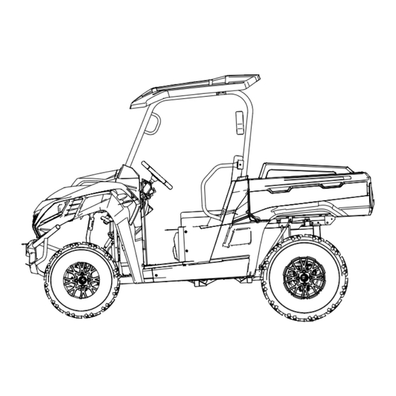
- Page 10 CHAPTER 1 GENERAL INFORMATION SERVICE MANUAL VEHICLE DIMENSIONS Note. The on-road equipments (rear view mirror, turn lights, etc.) are not Standard Equipment for USA. PAGE. 1- 6 CHAPTER 1 GENERAL...
- Page 11 CHAPTER 1 GENERAL INFORMATION SERVICE MANUAL NOTES PAGE. 1- 7 CHAPTER 1 GENERAL...
-
Page 12: Chapter2
CHAPTER 2 MAINTENANCE SERVICE MANUAL CHAPTER 2 MAINTENANCE The parts of different types/ variants/ versions maybe un-interchangeable, even some parts have almost same appearance. Always refer to Parts Manual of each UTV model for spare parts information and service. 2.1 PERIODIC MAI NTENANCE 2.2 THROTTLE PE DAL INSPECTION 2.3 FUEL SYSTEM 2.4 TOE ALIGNME NT... - Page 13 CHAPTER 2 MAINTENANCE SERVICE MANUAL 2.1 PERIODIC MAINTENANCE CAUTION Due to the nature of the adjustments marked with a D on the following chart, it is recommended that service be performed by an authorized dealer. More often under severe use, such as dirty or wet conditions to purge water or dirt contamination from grease fittings and other critical components.
- Page 14 CHAPTER 2 MAINTENANCE SERVICE MANUAL Sediment Daily Daily Drain deposits whenever visible Tube Check operation daily; apply dielectric Headlamp Inspection Daily Daily grease to connector when replaced Tail / Indicator Lamp Check operation daily; apply dielectric Daily Daily Inspection grease to socket when replaced Filter-Main Weekly...
- Page 15 CHAPTER 2 MAINTENANCE SERVICE MANUAL Fuel Filter 100 hrs 12 months Replace annually Radiator 100 hrs 12 months Inspect/clean external surface Clean out-replace if Spark Arrestor 50 hrs 3 months necessary Clutches (drive and 25 hrs 3 months Inspect, clean driven) Engine Mounts 25 hrs...
- Page 16 CHAPTER 2 MAINTENANCE SERVICE MANUAL ※---Check the protective boots for holes or tears, If any damage is found, have them replaced by an authorized dealer. LUBRICATION RECOMMENDATIONS NOTE: 1.More often under severe use, such as wet or dusty conditions. 2.Grease: Light weight lithium-soap grease. 3.Grease M:Molybdenum disulfide (MoS ) grease (water resistant).
- Page 17 CHAPTER 2 MAINTENANCE SERVICE MANUAL 2.2 THROTTLE PEDAL INSPECTION THROTTLE FREEPLAY If the throttle pedal has excessive play due to cable stretch or cable misadjustment, it will cause a delay in throttle speed. Also, the throttle may not open fully. If the throttle pedal has no play, the throttle may be hard to control, and the idle speed may be erratic.
- Page 18 CHAPTER 2 MAINTENANCE SERVICE MANUAL short time. Never drain the float bowl when the engine is hot. Severe burns may result. FUEL LINES 1. Check fuel lines for signs of wear, deterioration, damage or leakage. Replace if necessary. 2. Be sure fuel lines are routed properly and secured with cable ties.
- Page 19 CHAPTER 2 MAINTENANCE SERVICE MANUAL Always pay attention to tie rods assembly, Both ends must screw in same and enough threads length. Both ends must screw in same and enough threads length. Never tamper (cut) the rod. CHAPTER 2 MAINTENANCE PAGE.
- Page 20 CHAPTER 2 MAINTENANCE SERVICE MANUAL 2.5 SUSPENSION SPRING RPELOAD ADJUSTMENT Operator weight and vehicle loading affect suspension spring preload requirements. Adjust as necessary. FRONT AND REAR SUSPENSION Compress and release suspension. Damping should be smooth throughout the range of travel. Check all suspension components for wear or damage.
- Page 21 CHAPTER 2 MAINTENANCE SERVICE MANUAL torque listed in the table. On wheel nuts, Make sure tapered end of nut goes into taper on wheel. Wheel Nut Torque Specifications Bolt Size Specification Front M12X1.25 49 Ft.Lbs 66 Nm Rear M12X1.25 49 Ft.Lbs 66 Nm CAUTION: If wheels are improperly installed it could affect Vehicle handling and tire wear.
- Page 22 CHAPTER 2 MAINTENANCE SERVICE MANUAL NOTES CHAPTER 2 MAINTENANCE PAGE. 2- 11...
- Page 23 CHAPTER 3 ENGINE XY5000UTV SERVICE MANUAL 2022/ version number 2201 CHAPTER 3 ENGINE 3.1 MAINTENANCE SPECIFICATIONS 3.1.1 SPECIFICATIONS 3.1.2 TIGHTENING TORQUES 3.2 PARTS INSPECTION AND SE RVICE 3.2.1 VALVE CLEARANCE ADJUSTMENT 3.2.2 SPARK PLUG INSPECTION 3.2.3 COMPRESSION PRESSURE 3.2.4 ENGINE OIL LEVEL INSPECTION 3.2.5 ENGINE OIL REPLACEMENT 3.2.6 ENGINE OIL PRESSURE INSPECTION 3.2.7 COOLANT LEVEL INSPECTION...
- Page 24 CHAPTER 3 ENGINE XY5000UTV SERVICE MANUAL 2022/ version number 2201 3.1 MAINTENANCE SPECIFICATIONS 3.1.1 SPECIFICATIONS Item Standard Limit Cylinder head: Warp limit 0.07 mm Cylinder: Bore size 92.000 - 92.015 mm 92.025 mm Out of round limit 0.01 mm Camshaft: Cam dimensions Intake "A"...
- Page 25 CHAPTER 3 ENGINE XY5000UTV SERVICE MANUAL 2022/ version number 2201 Item Standard Limit Guide inside diameter 6 - 6.015 mm 6.05 mm 6 - 6.015 mm 6.05 mm Stem-to-guide clearance 0.035 - 0.065 mm 0.08 mm 0.035 - 0.065 mm 0.1 mm Stem runout limit …...
-
Page 26: Chapter3
CHAPTER 3 ENGINE XY5000UTV SERVICE MANUAL 2022/ version number 2201 I te m Standard Limit Throttle Body: No Adjustment Type Oil pump: Trochoid Type 0.1 - 0.34 mm 0 .4 mm Tip clearance Side clearance 0.013 - 0.036 mm 0.15 mm 0 .04 - 0.09 mm 0.15 mm Housing and rotor clearance... - Page 27 CHAPTER 3 ENGINE XY5000UTV SERVICE MANUAL 2022/ version number 2201 Tightening Torque Part Thread Part to be tightened Q’ty Remarks name size m.kg Trigger Bolt Right cover Bolt Timing check plug Bolt Cylinder head cover Bolt Cylinder head side cover Bolt Timing chain adjuster assy.
- Page 28 CHAPTER 3 ENGINE XY5000UTV SERVICE MANUAL 2022/ version number 2201 3.2 PARTS INSPECTION AND SERVICE 3.2.1 VALVE CLEARANCE ADJUSTMENT NOTE: Valve clearance adjustment should be made with the engine cool, at room temperature. When the valve clearance is to be measured or adjusted, the piston must be at Top Dead Center (T.D.C.) on the compression.
- Page 29 CHAPTER 3 ENGINE XY5000UTV SERVICE MANUAL 2022/ version number 2201 Measure the valve clearance. If the clearance is incorrect, repeat above steps until specified clearance is obtained. 7. Install: Refer to the reverse steps of disassembly for assembly. If the gasket between the cylinder head cover and the cylinder head is damaged, please replace it.
- Page 30 CHAPTER 3 ENGINE XY5000UTV SERVICE MANUAL 2022/ version number 2201 3.2.3 COMPRESSION PRESSURE NOTE: Insufficient compression pressure will result in performance loss. 1. Check: Valve clearance Out of specification Adjust. Refer to “3.2.1 VALVE CLEARANCE ADJUSTMENT” section. 2. Start the engine and let it warm up for several minutes.
- Page 31 CHAPTER 3 ENGINE XY5000UTV SERVICE MANUAL 2022/ version number 2201 Compression pressure (at sea level): Standard: 1,140 kPa (11.6kgf/cm ,11.4bar) Minimum: 912kPa (9.3kgf/cm ,9.1bar) Measurement steps: Crank the engine with the throttle wide open until reading on the compression gauge stabilizes. WARNING: Before cranking the engine, ground all spark plug leads to prevent sparking.
- Page 32 CHAPTER 3 ENGINE XY5000UTV SERVICE MANUAL 2022/ version number 2201 3.2.5 ENGINE OIL REPLACEMENT 1. Start the engine and let it warm up for several minutes. 2. Turn off the engine and place an oil pan under the engine. 3. Remove: ...
- Page 33 CHAPTER 3 ENGINE XY5000UTV SERVICE MANUAL 2022/ version number 2201 NOTE: Wipe any spilled oil off the engine. 3.2.7 COOLANT LEVEL INSPECTION Inspect: Coolant level 1. Start the engine and let it warm up for several minutes. 2. Turn off the engine and inspect the coolant level again.
- Page 34 CHAPTER 3 ENGINE XY5000UTV SERVICE MANUAL 2022/ version number 2201 Place a thick rag or a towel over the radiator cap. Slowly rotate the cap counterclockwise toward the detent. This allows any residual pressure to escape. When the hissing sound has stopped, press down on the cap while turning counterclockwise and remove it.
- Page 35 CHAPTER 3 ENGINE XY5000UTV SERVICE MANUAL 2022/ version number 2201 Total amount: 2L (including water pipe) Reservoir tank capacity: 0.35L HANDLING NOTES FOR COOLANT: Coolant is potentially harmful to environment and should be handled with special care. WARNING: Splashes in your eyes: Thoroughly wash your eyes with water and consult a doctor.
- Page 36 CHAPTER 3 ENGINE XY5000UTV SERVICE MANUAL 2022/ version number 2201 3.3 CYLINDER HEAD AND CYLINDER COMPONENTS Order Job name / Part name Q’ty Remarks BOLT M6×28 CYLINDER HEAD COVER GASKET,CYLINDER HEAD COVER BOLT M6×20 SCREWED PLUG M16×1.5 ALUMINUM WASHER 16 CYLINDER HEAD SIDE COVER BOLT M10×190×1.5 WASHER 10...
- Page 37 CHAPTER 3 ENGINE XY5000UTV SERVICE MANUAL 2022/ version number 2201 Order Job name / Part name Q’ty Remarks O-RING 21.5×5 THERMOSTAT HOUSING BOLT M6×20 ALUMINUM WASHER 10 COOLANT SENSOR GASKET, CYLINDER HEAD CYLINDER HEAD REMOVAL 1. Remove: Cylinder head cover ...
- Page 38 CHAPTER 3 ENGINE XY5000UTV SERVICE MANUAL 2022/ version number 2201 9. Remove: ○ Bolt M6×28 ○ Bolt M10×190×1.5 NOTE: Loosen the nuts in their proper loosening sequence. Loosen the bolts from a to d; Start by loosening each nut 1/2 turn until all are loose.
- Page 39 CHAPTER 3 ENGINE XY5000UTV SERVICE MANUAL 2022/ version number 2201 CYINDER HEAD INSTALLATION 1. Install: Gasket (Cylinder Head) (NEW) Pin Dowel 15×20 Cylinder Head 2. Install: ○ Washer 10 ○ Copper Washer 10 ○ Bolt M10×190×1.5 3.
- Page 40 CHAPTER 3 ENGINE XY5000UTV SERVICE MANUAL 2022/ version number 2201 4. Install: Timing chain tensioner Installing steps: Rotate the hole in the timing chain tensioner with ○ slotted screwdriver to make 1 indent, and hold slotted screwdriver; ○ Install the tensioner with a new gasket 2 onto the Cylinder;...
- Page 41 CHAPTER 3 ENGINE XY5000UTV SERVICE MANUAL 2022/ version number 2201 3.4 CAMSHAFT AND ROCKER ARMS Order Job name / Part name Q’ty Remarks NUT M6 SLOTTED SET SCREW WITH CONE POINT M6×17 ROCKER SHAFT INTAKE SIDE ROCKER ARM VALVE EXHAUST SIDE ROCKER ARM VALVE CAMSHAFT DECOMPRESSION RETURN SPRING VACUUM CENTRIFUGE AXIS...
- Page 42 CHAPTER 3 ENGINE XY5000UTV SERVICE MANUAL 2022/ version number 2201 CAMSHAFT INSPECTION 1. Inspect: Cam lobes Pitting/Scratches/Blue discoloration →Replace. 2. Measure: Cam lobes length ⓐ and ⓑ Out of specification → Replace. Cam lobes length: Intake: ⓐ 32.76 - 32.80 mm <Limit: 32.63 mm>...
- Page 43 CHAPTER 3 ENGINE XY5000UTV SERVICE MANUAL 2022/ version number 2201 Measure the outside diameter B of the rocker arm shafts. Out of specification → Replace. Outside diameter (rocker arm shaft): 21.973- 21.984 mm < Limit: 21.94 mm > CAMSHAFT AND ROCKER ARM INSTALLATION 1.
- Page 44 CHAPTER 3 ENGINE XY5000UTV SERVICE MANUAL 2022/ version number 2201 3.5 VALVES AND VALVE SPRINGS Order Job name / Part name Q’ty Remarks COTTER VALVE RETAINER SPRING VALVE SPRING VALVE VALVE SEAL ASSY. EXHAUST VALVE INTAKE VALVE VALVES AND VALVE SPRINGS REMOVAL 1.
- Page 45 CHAPTER 3 ENGINE XY5000UTV SERVICE MANUAL 2022/ version number 2201 VALVE AND VALVE SPRINGS INSPECTION 1. Measure: Valve stem diameter Out of specification → Replace. Valve stem diameter: Intake: 5.95 - 5.965 mm <Limit: 5.91mm> Intake: 5.95 - 5.965 mm <Limit: 5.91mm>...
- Page 46 CHAPTER 3 ENGINE XY5000UTV SERVICE MANUAL 2022/ version number 2201 7. Measure: Stem-to guide clearance Out of specification → Replace the valve guide. Stem-to-guide clearance limit: Intake: 0.08 mm Exhaust: 0.10 mm VALVE SEATS INSPECTION 1. Eliminate: Carbon deposits (from the valve face and valve seat) 2.
- Page 47 CHAPTER 3 ENGINE XY5000UTV SERVICE MANUAL 2022/ version number 2201 CAUTION: Do not let compound enter the gap between the valve stem and the guide. Apply molybdenum disulfide oil to the valve stem. Install the valve into the cylinder head. ...
- Page 48 CHAPTER 3 ENGINE XY5000UTV SERVICE MANUAL 2022/ version number 2201 3. Install: ○ Valve seal assy. (NEW) ○ Valve (into the cylinder head) ○ Valve spring ○ Retainer spring valve NOTE: ○ Install the valve spring with the larger pitch facing upwards.
- Page 49 CHAPTER 3 ENGINE XY5000UTV SERVICE MANUAL 2022/ version number 2201 3.6 CYLINDER AND PISTON Order Job name / Part name Q’ty Remarks BOLT M10×70 BOLT M10×78 CYLINDER BOLT M6×28 CLIP PISTON PIN PISTON TOP RING PISTON 2ND RING SCRAPPER RING OIL CONTROL RING PISTON DOWEL PIN 15×20...
- Page 50 CHAPTER 3 ENGINE XY5000UTV SERVICE MANUAL 2022/ version number 2201 PISTON AND PISTON RINGS REMOVAL 1. Remove: ○ Piston pin circ lip ○ Piston pin ○ Piston NOTE: Before removing the piston pin circ lip, cover the crankcase opening with a clean towel or rag to prevent the circ lip from falling into the crankcase cavity.
- Page 51 CHAPTER 3 ENGINE XY5000UTV SERVICE MANUAL 2022/ version number 2201 2. Measure: Warpage Out of specification → Replace. Cylinder warpage limit: 0.05 mm PISTON AND PISTON PIN INSPECTION 1. Measure: Piston skirt diameter Out of specification → Replace. ○...
- Page 52 CHAPTER 3 ENGINE XY5000UTV SERVICE MANUAL 2022/ version number 2201 PISTON RINGS INSPECTION 1. Measure: ○ Side clearance Out of specification → Replace the piston and the piston rings as a set. NOTE: Eliminate the carbon deposits from the piston ring grooves and rings before measuring the side clearance.
- Page 53 CHAPTER 3 ENGINE XY5000UTV SERVICE MANUAL 2022/ version number 2201 NOTE: Make sure to install the piston rings so that the manufacturer’s m arks or numbers are located on the upper side of the rings. Lubricate the pistons and piston rings liberally with engine oil.
- Page 54 CHAPTER 3 ENGINE XY5000UTV SERVICE MANUAL 2022/ version number 2201 3.7 V-BELT AND CLUTCH Order Job name / Part name Q’ty Remarks ACTIVE CLUTCH ASSY. ACTIVE CLUTCH INSTALLATION SLEEVE A BOLT M12×170×1.25 V-BELT DRIVEN CLUTCH ASSY. DRIVEN CLUTCH INSTALLATION SLEEVE D DRIVEN CLUTCH BOLT BOLT M6×32 CVT UPPER COVER COMPONETS...
- Page 55 CHAPTER 3 ENGINE XY5000UTV SERVICE MANUAL 2022/ version number 2201 2. Remove: Driven clutch assy. V-belt V-BELT INSPECTION 1. Inspect: ○ V-belt Cracks / Wear / Scaling / Chipping → Replace. 2. Measure: ○ V-belt width Out of specification →...
- Page 56 CHAPTER 3 ENGINE XY5000UTV SERVICE MANUAL 2022/ version number 2201 3.8 A.C. MAGNETO, STARTER CLUTCH AND MAGNETO COVER Order Job name / Part name Q’ty Remarks STARTING CLUTCH BUSHING A STARTING CLUTCH ASSY. LOCATING PIN 6×12 RIGHT CRANKCASE GASKET RIGHT CRANKCASE COVER SCREWED PLUG M14×1.5 OUTLET PIPE,RIGHT CRANKCASE COVER AIR INLET GRID...
- Page 57 CHAPTER 3 ENGINE XY5000UTV SERVICE MANUAL 2022/ version number 2201 2. Remove: Bolt M6×22 Cooling fan 3. Remove: Nut M16×1.5 Washer 16×31×1 4. Remove: Rotor assy. NOTE: ○ Remove the rotor assy. with a three-jaw puller ...
- Page 58 CHAPTER 3 ENGINE XY5000UTV SERVICE MANUAL 2022/ version number 2201 3. Install: Washer 16×31×1 Nut M16×1.5 NOTE: Apply Threadlocker (LOCTITE 263) onto the nut threads. ○ Tighten the nut (rotor) 1 while holding the ○ ○ magneto rotor 2 with a holder CHAPTER 3 ENGINE...
- Page 59 CHAPTER 3 ENGINE XY5000UTV SERVICE MANUAL 2022/ version number 2201 3.9 OIL PUMP Order Job name / Part name Q’ty Remarks CIRCLIP FOR SHAFT 12 OIL PUMP DRIVEN GEAR HEXAGON SOCKET HEAD CAP SCREW M6×45 HEXAGON SOCKET HEAD CAP SCREW M6×50 OIL PUMP ASSY.
- Page 60 CHAPTER 3 ENGINE XY5000UTV SERVICE MANUAL 2022/ version number 2201 Side clearance (Between the outer rotor○ 2 and the pump housing○ 3 ) Housing and rotor clearance (Between the pump housing○ 3 and the rotors○ 1 ○ 2 ) Out of specification →...
- Page 61 CHAPTER 3 ENGINE XY5000UTV SERVICE MANUAL 2022/ version number 2201 3.10 CRANKCASE AND CRANKSHAFT Order Job name / Part name Q’ty Remarks CRANKSHAFT LUBRICATION PIPE O-RING 10×2 LOCATING PIN 12×18 CRANKSHAFT ASSY. WOODRUFF KEY BALABCE SHAFT ASSY. CAM CHAIN CAM CHAIN GUIDE ROUND NUT M28×1.5 CRANKSHAFT SPROCKET BOLT M8×90...
- Page 62 CHAPTER 3 ENGINE XY5000UTV SERVICE MANUAL 2022/ version number 2201 CRANKSHAFT INSPECTION 1. Measure: Crankshaft runout Out of specification → Replace crankshaft and / or bearing. NOTE: Measure the crankshaft runout with the crankshaft assembly running slowly. Runout limit: 0.03 mm 2.
- Page 63 CHAPTER 3 ENGINE XY5000UTV SERVICE MANUAL 2022/ version number 2201 3.11 WATER PUMP Order Job name / Part name Q’ty Remarks BOLT M6×55 WATER PUMP HOSE CLAMP 20/32 WATER PUMP HOSE O-RING 44×2.5 CIRCLIP 12 BEARING 6001 WATER PUMP BODY AXLE SLEEVE OIL SEAL 12×24×5 MECHANICAL SEAL...
- Page 64 CHAPTER 3 ENGINE XY5000UTV SERVICE MANUAL 2022/ version number 2201 INSPECTION 1. Inspect: Impeller shaft Wear/damage → Replace. Fur deposits → Clean. 2. Inspect: ○ Mechanical seal Damage/worn/wear → Replace. WATER PUMP INSTALLATION 1. Install: Axle sleeve 2.
- Page 65 CHAPTER 3 ENGINE XY5000UTV SERVICE MANUAL 2022/ version number 2201 6. Install: ○ 4 NEW Circlip 12 7. Install: Water pump impeller 8. Install: ○ O-ring 5 NEW 9. Install: Water pump cover Bolt M6×20 ...
- Page 66 CHAPTER 3 ENGINE XY5000UTV SERVICE MANUAL 2022/ version number 2201 3.12 Transmission assembly Failure analysis and repair of the transmission assembly refer to the table: Fault type Possible causes of failure Measures Maintenance Reference Shift shaft leakage Oil seal damage Replace Remove the gearshift mechanism Crankshaft oil seal or spindle...
- Page 67 CHAPTER 3 ENGINE XY5000UTV SERVICE MANUAL 2022/ version number 2201 3.12.1 SHIFTING MECHANISM Order Job name / Part name Q’ty Remarks BOLT M6×20 GEAR POSITION SENSOR O-RING 27×2.5 SCREW M6×12 LIMIT WASHER GEAR CONTACTOR GEAR CONTACTOR SPRING WASHER 32×40×2 SHIFT DRUM ASSY. WASHER 15×33×2 SHIFT DRUM BOLT SHIFT DRUM SPRING...
- Page 68 CHAPTER 3 ENGINE XY5000UTV SERVICE MANUAL 2022/ version number 2201 1. Inspect Gear position sensor Wear / damage → Replace. Gear contactor Wear / stuck → Replace. Shift drum assy. Wear / stuck → Replace. Shift gear assy. Wear / stuck →...
- Page 69 CHAPTER 3 ENGINE XY5000UTV SERVICE MANUAL 2022/ version number 2201 3.12.2 GEAR BOX Order Job name / Part name Q’ty Remarks OIL SEAL 25×40×7 O-RING 47×2.5 FRONT BEARING COVER BOLT M6×22 BEARING 6205 OUTPUT SHAFT BECEL GEAR LIMIT SLEEVE DRIVEN BEVEL GEAR WASHER 25×32×0.2 BOLT M8×28 NUT M16×1.5...
- Page 70 CHAPTER 3 ENGINE XY5000UTV SERVICE MANUAL 2022/ version number 2201 Order Job name / Part name Q’ty Remarks REVERSE DRIVEN GEAR NEUTRAL-REVERSE GEAR SHIFT DISC WASHER 23.5×33×1 CIRCLIPS FOR SHAFT 22 IDLER GEAR WASHER 26×35×1.5 LOW DRIVEN GEAR WASHER 26×35×1 COUNTER SHAFT HIGH-LOW GEAR SHIFT DISC DRIVE SHAFT...
- Page 71 CHAPTER 3 ENGINE XY5000UTV SERVICE MANUAL 2022/ version number 2201 1. Examination Oil seal Damage/wear/failure of inner spring → Replacement. Gear shift disc Spline damage / wear → Replacement. Burns / discoloration → Replacement. Counter shaft Wear / damage / substandard → replacement. ...
- Page 72 CHAPTER 3 ENGINE XY5000UTV SERVICE MANUAL 2022/ version number 2201 NOTES CHAPTER 3 ENGINE PAGE. 3- 50...
-
Page 73: Chapter4
CHAPTER 4 CHASSIS SERVICE MANUAL CHAPTER 4 CHASSIS WARNING The parts of different types/ variants/ versions maybe un-interchangeable, even some parts have almost same appearance. Always refer to Parts Manual of each CUV model for spare parts information and service. 4.1 FRONT SUSPE NSION REPLACEMENT 4.2 REAR SUSPENSION REPLACEME NT 4.3 FRONT STABILIZER BAR REMOVAL/INSTALLATION... - Page 74 CHAPTER 4 CHASSIS SERVICE MANUAL 4.1 FRONT SUSPENSION REPLACEMENT 1. Elevate and safely support vehicle with weight removed from front wheel(s). 2. Remove the wheel nuts and wheel. 3. loose and remove the bolts on front shock absorber, and remove the front shock absorber. 4.
- Page 75 CHAPTER 4 CHASSIS SERVICE MANUAL 14. Tight all bolts and nuts, check the torque by torque wrench. 15. Install wheels(tightening torque 66Nm), lower the vehicle to the ground. Enough lubricating grease should be supply for the A-arm steel shaft and rubber bushing. DO NOT reuse old bolts.
- Page 76 CHAPTER 4 CHASSIS SERVICE MANUAL 4.2 REAR SUSPENSION REPLACEMENT 1. Elevate and safely support vehicle with weight removed from the rear wheel(s). 2. Remove the wheel nuts and wheel. 3. loose and remove the bolts on rear shock absorber, and remove the rear shock absorber. 4.
- Page 77 CHAPTER 4 CHASSIS SERVICE MANUAL Enough lubricating grease should be supply for the A-arm steel shaft and rubber bushing. DO NOT reuse old bolts. Serious injury or death could result if fasteners come loose during operation. Upon A-arm installation completion, test vehicle at low speeds before putting into regular service.
- Page 78 CHAPTER 4 CHASSIS SERVICE MANUAL 4.3 FRONT STABILIZER BAR REMOVAL/INSTALLATION 1. Park the vehicle on the level ground 2. Loosen and remove bolts on front bumper, and remove front bumper. 3. Loose the connection nut between front stabilizer joint and lower A-arm. 4.
- Page 79 CHAPTER 4 CHASSIS SERVICE MANUAL 4.4 REAR STABILIZER BAR REMOVAL/INSTALLATION 1. Elevate and safely support vehicle with weight removed from the rear wheel(s). 2. Remove the wheel nuts and wheel. 3. Loose the connection nut between rear stabilizer joint and lower A-arm. 4.
- Page 80 CHAPTER 4 CHASSIS SERVICE MANUAL 4.5 BOX REMOVAL/INSTALLATION Box Removal 1. Disconnect the taillight coupler. 2. Lift the box into the dump position. 3. Remove the box shock pin and rubber pad and B type pin from the frame (both sides). 4.
- Page 81 CHAPTER 4 CHASSIS SERVICE MANUAL 4.6 STEERING ASSEMBLY REMOVAL/INSTALLATION 1. Remove the plastic cover of Ignition switch. 2. Loose and remove 4 bolts on ignition switch, remove the Ignition Switch. 3. Loose and remove 6 bolts on steering wheel, remove steering wheel and horn switch. 4.
- Page 82 CHAPTER 4 CHASSIS SERVICE MANUAL 4.7 GENERAL TIGHTENING TORQUE Size of bolt 25 Nm 35 Nm 55 Nm Torque of tightening (18 ft lbs) (26 ft lbs) (41 ft lbs) • • • CHAPTER 4 CHASSIS PAGE. 4- 10...
- Page 83 CHAPTER 4 CHASSIS SERVICE MANUAL NOTES CHAPTER 4 CHASSIS PAGE. 4- 11...
-
Page 84: Chapter5
CHAPTER 5 FINAL DRIVE SERVICE MANUAL CHAPTER 5 FINAL DRIVE WARNING The parts of different types/ variants/ versions maybe un-interchangeable, even some parts have almost same appearance. Always refer to Parts Manual of each CUV model for spare parts information and service. 5.1 WHEEL, HUB, AND SPINDLE TO RQUE TABLE 5.2 FRONT HUB EXPLODED VIEW 5.3 FRONT HUB REMOVAL/INSPECTION... - Page 85 CHAPTER 5 FINAL DRIVE SERVICE MANUAL 5.3 FRONT HUB REMOVAL/INSPECTION 1. Elevate front end and safely support machine under footrest / frame area. CAUTION: Serious injury may result if machine tips or falls. Be sure machine is secure before beginning this service procedure.
- Page 86 CHAPTER 5 FINAL DRIVE SERVICE MANUAL CAUTION: Do not hang the caliper by the brake line. Use wire to hang the caliper to prevent possible damage to the brake line. 6. Remove hub cap, cotter pin, front spindle nut, and washer, separate hub from front driveshaft.
- Page 87 CHAPTER 5 FINAL DRIVE SERVICE MANUAL CAUTION: New bolts have a pre-applied locking agent which is destroyed bolts upon removal. Always use new brake caliper mounting bolts upon assembly. 8. Install wheel and wheel nuts and tighten evenly in a cross pattern to specified torque. 5.5 FRONT HUB BEARING REPLACEMENT 1.
- Page 88 CHAPTER 5 FINAL DRIVE SERVICE MANUAL 5.7 REAR HUB AND KNUCKLE REMOVAL/INSPECTION 1. Elevate rear end and safely support machine under main frame area. CAUTION: Serious injury may result if machine tips or falls. Be sure machine is secure before beginning this service procedure.
- Page 89 CHAPTER 5 FINAL DRIVE SERVICE MANUAL 6. Remove the upper and lower control arm bolts. 7. Slide the rear hub and knuckle from the rear drive shaft. 8. Inspect the rear hub and knuckle assembly by hand for smoothness and side to side movement, replace as needed.
- Page 90 CHAPTER 5 FINAL DRIVE SERVICE MANUAL 5.10 REAR DRIVE SHAFT INSTALLATION 1. Install a new circlip onto the rear drive shaft. Apply Anti-Seize Compound onto the rear driveshaft splines (both ends). 2. Reinstall the rear driveshaft into the rear gearcase. Be sure the circlip is securely fit into the rear gearcase.
- Page 91 CHAPTER 5 FINAL DRIVE SERVICE MANUAL NOTES CHAPTER 5 FINAL DRIVE. 5-...
- Page 92 CHAPTER 6 BRAKES SERVICE MANUAL CHAPTER 6 BRAKES 6.1 SPECIFICATIONS 6.2 TORQUE 6.3 BRAKE SYSTEM SERVICE NOTE S 6.4 BURNISHING PROCEDURE 6.5 BRAKE BLEEDING-FLUID CHANGE 6.6 PARKING BRAKE AND BRAKE LINE INSPECTION 6.7 PARKING BRAKE ADJUSTMENT 6.8 REAR PADS REMOVAL/INSTALL 6.9 FRONT PADS INSPECTION / REMOVAL / REPLACEMENT 6.10 FRONT DISC I NSPECTION / RE MOVAL / REPLACEMENT 6.11 FRONT CALIPER REMOVAL/ INSPECTION / INSTALLATION...
- Page 93 CHAPTER 6 BRAKES SERVICE MANUAL 6.1 SPECIFICATIONS Front Brake Caliper Item Standard Service Limit Brake Pad Friction material 0.236"/ 6mm 0.04"/ 1mm Thickness Brake Disc Thickness 0.189-0.203"/4.81-5.166 mm 0.179"/ 4.556mm Brake Disc Thickness Variance 0.002 "/ .051m m Between Measurements Brake Disc Runout 0.005 "/ .127mm Rear Brake Caliper...
- Page 94 CHAPTER 6 BRAKES SERVICE MANUAL Make sure atmospheric vent on reservoir is unobstructed. Adjust foot brake after pad service. Test for brake drag after any brake system service and investigate cause if brake drag is evident. Make sure caliper moves freely on guide pins (where applicable) . ...
- Page 95 CHAPTER 6 BRAKES SERVICE MANUAL 1. Clean reservoir cover thoroughly. 2. Remove cover from reservoir. 3. If changing fluid, remove old fluid from reservoir with a brake fluid pump or similar tool. 4. Add brake fluid between the MIN line and MAX line of reservoir.
-
Page 96: Chapter6
CHAPTER 6 BRAKES SERVICE MANUAL 6.6 PARKING BRAKE AND BRAKE LINE INSPECTION 1. Inspect the spring on the parking brake lever assembly. 2. Inspect the parking brake cable at the parking brake lever assembly on the brake caliper. 3. Inspect the brake cable and brake cable connections for possible leaks or loose cable. - Page 97 CHAPTER 6 BRAKES SERVICE MANUAL 6.7 PARKING BRAKE ADJUSTMENT Parking Brake Inspection 1. Put your foot on the parking pedal. 2. After 3 to 4 clicks of lever travel, the vehicle should not roll while parked. 3. If the vehicle moves, adjustment is necessary. 4.
- Page 98 CHAPTER 6 BRAKES SERVICE MANUAL 3. Measure the thickness of the caliper parking brake pads. Replace pads if worn beyond the service limit. Service Limit 3/64"(1 mm) The Procedure of Pads Replacement 1. Push caliper piston into caliper bore slowly using a C-clamp or locking pliers with pads installed.
- Page 99 CHAPTER 6 BRAKES SERVICE MANUAL 6.9 FRONT PADS REMOVAL / INSPECTION / INSTALLATION NOTE: The brake pads should be replaced as a set. REMOVAL 1. Elevate and support front of CUV safely. CAUTION: Be care when supporting vehicle so that it does not tip or fall.
- Page 100 CHAPTER 6 BRAKES SERVICE MANUAL REMOVAL / REPLACEMENT 6.10 FRONT DISC INSPECTION / INSPECTION 1. Visually inspect the brake disc for nicks, scratches, or damage. 2. Measure the disc thickness at 8 different points around the pad contact surface using a 0-1" micrometer and a dial indicator.
- Page 101 CHAPTER 6 BRAKES SERVICE MANUAL 6.11 FRONT CALIPER REMOVAL/ INSPECTION / INSTALLATION CAUTION: The caliper is a non-serviceable Component, it must be replaced as an assembly. NOTE: If any special service needed, contact the CUV manufacture via the agent for the parts and special instruction.
- Page 102 CHAPTER 6 BRAKES SERVICE MANUAL from brake hose. 3. After the fluid has drained into the container, remove the caliper mounting bolts and remove caliper. 4. Remove brake pads as described above. 5. Inspect surface of caliper for nicks, scratches or damage and replace if necessary. 6.
- Page 103 CHAPTER 6 BRAKES SERVICE MANUAL NOTES CHAPTER 6 BRAKES PAGE. 7- 12...
- Page 104 CHAPTER 7 ELECTRICAL CUV SERVICE MANUAL 09.0 CHAPTER 7 ELECTRICAL BATTERY IGNITION SYSTEM CHARGING SYSTEM ELECTRICS STARTING SYSTEM COOLING SYSTEM LIGHTING SYSTEM REVERSE LIMIT SYSTEM GEAR POSITION INDICATOR SWITCH TEST SPEEDOMETER SYSTEM 7.10 TFT METER 7.11 KEY SWITCH 7.12 FUEL GAUGE/ FUEL LEVEL SENSOR 7.13 WIRING DIAGRAM CHAPTER 7...
- Page 105 CHAPTER 7 ELECTRICAL CUV SERVICE MANUAL 09.0 7.1 BATTERY Battery electrolyte is poisonous. It contains sulfuric acid. Serious burns can result from contact with skin, eyes or clothing Antidote: External: Flush with water. lnternal: Drink large quantities of water or milk. Follow with milk of magnesia, beaten egg, or vegetable oil.
- Page 106 CHAPTER 7 ELECTRICAL CUV SERVICE MANUAL 09.0 Test, Specific Gravity Test and Load Test. MF (Maintenance Free) battery does not require the Specific Gravity Test and Refill Open Circuit Voltage Test Battery voltage should be checked with a multimeter NOTE: Lead acid batteries should be kept at or near a full digital multitester. Readings of 12.6 or less require further battery testing and charging.
- Page 107 CHAPTER 7 ELECTRICAL CUV SERVICE MANUAL 09.0 7.2 IGNITION SYSTEM IGNITION SYSTEM TROUBLESHOOTING No Spark, Weak or Intermittent Spark Spark plug gap incorrect Fouled spark plug Faulty spark plug cap or poor connection to high tension lead ...
- Page 108 CHAPTER 7 ELECTRICAL CUV SERVICE MANUAL 09.0 CIRCUIT DIAGRAM REC/REG REC/REG Spark Spark Plug Plug Battery Battery Start Start relay relay switch switch CHAPTER 7 FINAL DRIVE. 7-...
- Page 109 CHAPTER 7 ELECTRICAL CUV SERVICE MANUAL 09.0 IF THE IGNITION SYSTEM FAILS TO OPERATE Procedure Check: 1. Fuse (Main) 7. Main switch 2. Battery 8. Emergency stop switch 3. Spark plug 9. Wiring connection 4. lgnition spark gap (entire ignition system) 5.
- Page 110 CHAPTER 7 ELECTRICAL CUV SERVICE MANUAL 09.0 4.lgnition spark gap Disconnect the spark plug cap from the spark plug Connect the ignition tester 1 as shown. 2 Spark plug Turn the main switch to "ON". Check the ignition spark gap . Check the spark by pushing the starter switch, and increase the spark gap until a misfire occurs.
- Page 111 CHAPTER 7 ELECTRICAL CUV SERVICE MANUAL 09.0 Tester (+) lead Pink Terminal Tester ( ) lead B/Y 6. Ignition coil resistance Terminal Disconnect the ignition coil connector from the wire harness. Connect the pocket tester (1) to the ignition coil. ...
- Page 112 CHAPTER 7 ELECTRICAL CUV SERVICE MANUAL 09.0 CONTINIUTY 8.Emergency stop switch NO CONTINUITY CHECK SWITCHES Replace the emergency stop switch CONTINIUTY 9.Wiring connection Check the connection of the POOR CONNECTIONS entire ignition system Refer to ―CIRCUIT DIAGRAM‖ Correct CORRECT Replace the igniter unit. CHAPTER 7 FINAL DRIVE.
- Page 113 CHAPTER 7 ELECTRICAL CUV SERVICE MANUAL 09.0 7.3 CHARGING SYSTEM CHARGING SYSTEM CIRCUIT DIAGRAM Battery Battery Main Main Fuse Fuse A.C Magneto Magneto 12V 30Ah 30Ah CURRENT DRAW - KEY OFF CAUTION: Do not connect or disconnect the battery cable or ammeter with the engine running. Damage will occur to light bulbs and speed limiter.
- Page 114 CHAPTER 7 ELECTRICAL CUV SERVICE MANUAL 09.0 2. Battery Check the battery condition. INCORRECT Refer to "BATTERY INSPECTION" Clean battery terminals Recharge or replace the battery 3.Charging voltage Connect the engine tachometer to the spark plug lead. pocket tester Connect (DC20V) to the battery Test (+) lead→...
- Page 115 CHAPTER 7 ELECTRICAL CUV SERVICE MANUAL 09.0 MEETS SPECIFICATION 5.Wiring connection check the entire charging system for connections Refer to “CIRCUIT DIAGRAM” POOR CONNECTION correct CORRECT Replace the rectifier/regulator CHAPTER 7 ELECTRICAL CTRICAL PAGE 7- 12...
- Page 116 CHAPTER 7 ELECTRICAL CUV SERVICE MANUAL 09.0 7.4 ELECTRICS STARTING SYSTEM D I A G R A M Battery Battery Start relay Start motor Key switch TROUBLESHOOTING IF THE STARTER MOTOR FAILS TO OPERATE Procedure Check: 1. Fuse (Main) 6. neutral switch 2.
- Page 117 CHAPTER 7 ELECTRICAL CUV SERVICE MANUAL 09.0 1. fuse refer “CHECKING SWITCHES” NO CONTINUITY section Replace the fuse 2. Battery Check the battery condition. INCORRECT Refer to "BATTERY INSPECTION" section in CHAPTER 3 Clean battery terminals Recharge or replace the battery 3.
- Page 118 CHAPTER 7 ELECTRICAL CUV SERVICE MANUAL 09.0 CONTINUITY Replace the starter replay 5.Key switch CHECK SWITCHES NO CONTINUITY Replace the main switch 6. Neutral switch NO CONTINUITY CHECKING SWITCHES Replace the brake switch 7 Wiring connection POOR CONNECTION Check the connections of the entire starting system.
- Page 119 CHAPTER 7 ELECTRICAL CUV SERVICE MANUAL 09.0 7.5 COOLING SYSTEM IF THE FAN MOTOR FAILS TO TURN Procedure Check: 1. Fuse (Main, Fan) 4. Fan motor (inspection) 2. Battery 5. Temperature control switch 3. Key switch 6.Relay 7. Wiring connection (entire cooling system) Cooling System Switch ON ON...
- Page 120 CHAPTER 7 ELECTRICAL CUV SERVICE MANUAL 09.0 Recharge or replace the battery 3 Key switch CHECK SWITCHES NO CONTINUITY Replace the main switch 4. Fan motor(inspection 1) Connect the battery to the fan motor. Battery (+) lead→Green/Blue terminal DOES NOT MOVE ...
- Page 121 CHAPTER 7 ELECTRICAL CUV SERVICE MANUAL 09.0 WARNING 7.Starter relay A wire used as a jumper lead must have equivalent capacity as that of the battery Disconnect the relay unit coupler from lead or more, otherwise it may the wire harness. burn.
- Page 122 CHAPTER 7 ELECTRICAL CUV SERVICE MANUAL 09.0 IF THE HEAT ALARM UNIT WORKING When the main switch is turned on, the temperature of the engine begins to go up. As it comes to 75±3℃ the thermostat is connected and the fan starts to work, cooling the coolant, if the thermostat or the fan, fails to work;...
- Page 123 CHAPTER 7 ELECTRICAL CUV SERVICE MANUAL 09.0 Handle the thermo unit with 4.Thermo unit special care. Drain the coolant and remove the Never subject it to strong thermo unit from the cylinder head. shocks or allow it to be Immerse the thermo unit in the dropped.
- Page 124 CHAPTER 7 ELECTRICAL CUV SERVICE MANUAL 09.0 POOR CONNECTION 7.Wiring connection check the connections of the entire cooling system. Refer to “CIRCUIT DIAGRAM” CORRECT Replace the temperature gauge CHAPTER 7 ELECTRICAL CTRICAL PAGE 7- 21...
- Page 125 CHAPTER 7 ELECTRICAL CUV SERVICE MANUAL 09.0 LIGHTING SYSTEM Lighting System Switch ON ON FUSE Ignition Ignition FUSE DC12V + DC12V + Flash H/L beam Headlight switch switch Turn R/Bl signal switch Turn signal switch W/Pu L Bl winch Gr/W Br/Y Shift Shift...
- Page 126 CHAPTER 7 ELECTRICAL CUV SERVICE MANUAL 09.0 3. Main switch NO CONTINUITY CHECK SWITCHES Replace the main switch 4. Light switch NO CONTINUITY CHECK SWITCHES Replace the light switch POOR CONNECTIONS 5.Wiring connection Check the connection of the entire lighting system correct 6.check the condition of each of the lighting system’s circuits...
- Page 127 CHAPTER 7 ELECTRICAL CUV SERVICE MANUAL 09.0 Turn the main switch to on. Turn the light switch to on position. Turn the dimmer switch to low beam or high beam. Check for voltage (12V) on the lead at OUT OF SPECIFICATION bulb socket connectors The wiring circuit from the main switch to...
- Page 128 CHAPTER 7 ELECTRICAL CUV SERVICE MANUAL 09.0 7.7 REVERSE LIMIT SYSTEM Meter Meter Speed is controlled by the ECU factory Settings In the 15 km/h, which can be reset in accordance with the user’s practice. CHAPTER 7 ELECTRICAL CTRICAL PAGE 7- 25...
- Page 129 CHAPTER 7 ELECTRICAL CUV SERVICE MANUAL 09.0 7.8 GEAR POSITION INDICATOR SWITCH TEST Switch table High High Range Range Low Range Range Neutral Neutral Reverse Reverse CHAPTER 7 ELECTRICAL CTRICAL PAGE 7- 26...
-
Page 130: Chapter7
CHAPTER 7 ELECTRICAL CUV SERVICE MANUAL 09.0 SPEEDMETER SYSTEM OPERATION OF SPPED SENSOR Speed Sensor is on the front axle Operation Instructions of Electric Dial Meter and Speed Sensor/ Operation Instructions of LCD Meter Speed Sensor Hall Sensor is a new type sensor used to measure speed, angle, revolution and length, etc by means of voltage pulse signals converted from sensing gear ratio of black metal gear or gear... - Page 131 CHAPTER 7 ELECTRICAL CUV SERVICE MANUAL 09.0 1, Align one tooth of the splines to the centre of the hole of the sensor by turning the rear axle. 2. Screw the senor in (CW) by hand slightly until resistance is felt. 3.
- Page 132 CHAPTER 7 ELECTRICAL CUV SERVICE MANUAL 09.0 7.10 TFT METER 1. Left Turn Indicator 13. Neutral indicator 2. EFI fault indicator 14. Reverse indicator 3. Function button “SET” 15. Engine RPM 4. Parking indicator 16. Gear indication 5. Low fuel level warning 17.
- Page 133 CHAPTER 7 ELECTRICAL CUV SERVICE MANUAL 09.0 Driving mode 4WD-FRONT DIFFERENTIAL LOCK REAR DIFFERENTIAL LOCK Key function: Short Press Button SET: Adjust backlight brightness; Short Press Button SEL: Trip A, Trip B switch; Long Press Button SEL: Trip A or Trip B reset; Long Press Button SET&SEL : Clock setting mode Clock setting mode: short press SEL:adjust the flashing position...
- Page 134 CHAPTER 7 ELECTRICAL CUV SERVICE MANUAL 09.0 P0337 Crank sensor no signal P0351 EST1 malfunction P0500 VSS no valid signal P0505 Idle speed control P0562 System voltage low P0563 System voltage high P0601 EEPROM Checksum Error P0650 MIL malfunction ECU will store the fault code and eliminate it after 40 normal starts; If the fault code needs to be cleared in advance, it can be cleared by the EFI diagnostic apparatus or turned on and off the key switch quickly for 5 times.
- Page 135 CHAPTER 7 ELECTRICAL CUV SERVICE MANUAL 09.0 7.11 KEY SWITCH ON ON Bl/W START START connect connect to to horn horn switch switch CHAPTER 7 ELECTRICAL CTRICAL PAGE 7- 32...
- Page 136 CHAPTER 7 ELECTRICAL CUV SERVICE MANUAL 09.0 7.12 FUEL GAUGE/ FUEL LEVEL SENSOR Removal Turn the ignition switch to“OFF”. Remove two connecting pipe of oil pump. Remove the terminal of oil pump. Remove the oil pump cove Retain plate and fuel level sensor from the fuel tank.
- Page 137 CHAPTER 7 ELECTRICAL CUV SERVICE MANUAL 09.0 When shows that there are only two segments,segments should blink. With the fuel level sensor float at the top (FULL)position, turn the main switch to“ON” and check the fuel gauge. All segments up to segment“F”should come on.
- Page 138 CHAPTER 7 ELECTRICAL CUV SERVICE MANUAL 09.0 7.13 WIRING DIAGR CHAPTER 7 ELECTRICAL CTRICAL PAGE 7- 35...
- Page 139 CHAPTER 7 ELECTRICAL CUV SERVICE MANUAL 09.0 Battery Battery CHAPTER 7 ELECTRICAL CTRICAL PAGE 7- 36...
- Page 140 CHAPTER 7 ELECTRICAL CUV SERVICE MANUAL 09.0 Battery Battery Head Head Light Light Head Head Light Light Turn Turn signal signal Light(F,L) Light(F,L) Turn Turn signal signal Light(F,R) Light(F,R) Turn Turn signal signal Light(F,L) Light(F,L) Turn Turn signal signal Light(F,R) Light(F,R) Parking Switch Belt Switch...
- Page 141 CHAPTER 7 ELECTRICAL CUV SERVICE MANUAL 09.0 Battery Battery Water Water temperature temperature sensor sensor REC/REG REC/REG Spark Spark Plug Plug CHAPTER 7 ELECTRICAL CTRICAL PAGE 7- 38...
- Page 142 CHAPTER 7 ELECTRICAL CUV SERVICE MANUAL 09.0 NOTES CHAPTER 7 ELECTRICAL CTRICAL PAGE 7- 39...
Need help?
Do you have a question about the PANTHER 550 and is the answer not in the manual?
Questions and answers
93 550 PANTHER RUNNING LIKE THE CHOKE IS ON. BOGS DOWN WHEN GIVEN THROTTLE. ANY CLUES TO FIX?
Possible causes for a 1993 Arctic Cat Panther 550 running as if the choke is on and bogging down when the throttle is applied include:
1. Throttle Cable Issues – Excessive play or misadjustment in the throttle cable can cause improper throttle response. Inspect and adjust throttle freeplay as needed.
2. Clogged Carburetor Jets – Dirt or fuel residue in the carburetor jets can cause a rich fuel mixture, similar to a choke being stuck.
3. Stuck Choke – If the choke mechanism is stuck in the closed position, it will cause an overly rich fuel mixture, leading to bogging.
4. Air Filter Blockage – A dirty or clogged air filter can restrict airflow, making the engine run rich.
5. Spark Plug Issues – A fouled or incorrect spark plug can cause poor combustion, leading to loss of power.
6. Ignition System Problems – Weak spark from a faulty ignition coil or poor spark plug gap can affect engine performance.
7. Fuel Delivery Issues – A failing fuel pump, clogged fuel filter, or restricted fuel lines can cause improper fuel flow.
8. Vacuum Leaks – Leaks in intake boots or carburetor seals can disrupt the air-fuel mixture.
Inspect and troubleshoot these areas to identify and resolve the issue.
This answer is automatically generated
Location of spark plug on 2010 artic cat 550 h1
The spark plug on a 2010 Arctic Cat Panther 550 H1 is located on the engine cylinder head. To access it, you need to disconnect the spark plug cap and may need to use compressed air to clean the area before removing the spark plug.
This answer is automatically generated