Advertisement
Quick Links
Advertisement

Subscribe to Our Youtube Channel
Related Manuals for ProSoft Technology PS69-DPM


Summary of Contents for ProSoft Technology PS69-DPM
- Page 1 PS69-DPM CompactLogix or MicroLogix Platform PROFIBUS DPV1 Master October 1, 2014 USER MANUAL...
- Page 2 ® ProSoft Technology , is a registered copyright of ProSoft Technology, Inc. All other brand or product names are or may be trademarks of, and are used to identify products and services of, their respective owners. In an effort to conserve paper, ProSoft Technology no longer includes printed manuals with our product shipments.
- Page 3 PROSOFT.fdt (SYCON.net) ..................36 2.2.1 General ........................36 2.2.2 Create a New Project ....................37 2.2.3 Configuration of the PS69-DPM Master ..............39 2.2.4 Configuration of PROFIBUS Slaves ................ 42 2.2.5 Project Download ....................47 RSLogix 5000 (version 15 or lower) ................ 51 2.3.1...
- Page 4 Contents PS69-DPM ♦ CompactLogix or MicroLogix Platform User Manual PROFIBUS DPV1 Master 3.2.3 Standard Messaging ....................76 3.2.4 DPV1 Messaging ....................82 3.2.5 Messaging Error Codes ..................87 RSLogix Example Program CompactLogix I/O Example ..................92 CompactLogix Messaging Example ............... 92 Diagnostics and Troubleshooting Diagnostic Interface ....................
- Page 5 PS69-DPM ♦ CompactLogix or MicroLogix Platform Contents PROFIBUS DPV1 Master User Manual 6.3.16 DDLM_SLAVE_DIAGNOSTIC_CONFIRM ............115 6.3.17 DPM_DPV1_ALARM_INDICATION ..............116 6.3.18 DPV1_ALARM_INDICATION ................116 6.3.19 MSAC1_READ_REQUEST................... 117 6.3.20 MSAC1_READ_CONFIRM ................... 117 6.3.21 MSAC1_WRITE_REQUEST ................. 117 6.3.22 MSAC1_WRITE_CONFIRM.................. 118 6.3.23 MSAL1M_ALARM_RESPONSE ................118 6.3.24...
- Page 6 Contents PS69-DPM ♦ CompactLogix or MicroLogix Platform User Manual PROFIBUS DPV1 Master Page 6 of 130 ProSoft Technology, Inc. October 1, 2014...
- Page 7 PS69-DPM ♦ CompactLogix or MicroLogix Platform Contents PROFIBUS DPV1 Master User Manual Start Here In This Chapter General Information ................8 Software Requirements ................8 Hardware Requirements ................. 9 Reference Systems................. 9 Programmable Controller Functionality ..........10 ...
- Page 8 PROFIBUS DPV1 Master General Information The communication module PS69-DPM is a slot extension module for a CompactLogix or MicroLogix 1500 Controller which enables controllers to communicate with a PROFIBUS network. The PS69-DPM is a PROFIBUS-DP Master. The configuration and diagnostic of the PROFIBUS system is done via the serial diagnostic interface of the module using the System Configuration tool PROSOFT.fdt (SYCON.net).
- Page 9 PS69-DPM ♦ CompactLogix or MicroLogix Platform Contents PROFIBUS DPV1 Master User Manual Hardware Requirements The following minimum hardware is required to use the PS69-DPM PROFIBUS module. CompactLogix System Personal Computer 1769: Programmable Controller 1769: Power Supply ...
- Page 10 = functionality supported no = functionality not supported Package Contents The following components are included with your PS69-DPM module, and are all required for installation and configuration. Important: Before beginning the installation, please verify that all of the following items are present.
- Page 11 PS69-DPM ♦ CompactLogix or MicroLogix Platform Contents PROFIBUS DPV1 Master User Manual Installing the Module Before you attempt to install the module, make sure that the bus lever of the adjacent module is in the unlocked (fully right) position. Warning: This module is not hot-swappable! Always remove power from the rack before inserting or removing this module, or damage may result to the module, the processor, or other connected devices.
- Page 12 Contents PS69-DPM ♦ CompactLogix or MicroLogix Platform User Manual PROFIBUS DPV1 Master Push the module’s bus lever back slightly to clear the positioning tab and move it firmly to the left until it clicks. Ensure that it is locked firmly in place.
- Page 13 PS69-DPM ♦ CompactLogix or MicroLogix Platform Contents PROFIBUS DPV1 Master User Manual Press the DIN-rail mounting area of the controller against the DIN-rail. The latches will momentarily open and lock into place. ProSoft Technology, Inc. Page 13 of 130 October 1, 2014...
- Page 14 Contents PS69-DPM ♦ CompactLogix or MicroLogix Platform User Manual PROFIBUS DPV1 Master Sample Add-On Instruction Import Procedure Note: This section only applies if you are using RSLogix 5000 version 16 or higher. The following file is required before you start this procedure. Copy the file from the ProSoft Solutions DVD, or download it from Error! Hyperlink reference not valid..
- Page 15 PS69-DPM ♦ CompactLogix or MicroLogix Platform Contents PROFIBUS DPV1 Master User Manual 1.8.2 Create the Module … Right-click I/O Configuration and choose N ODULE Select 1769-MODULE ProSoft Technology, Inc. Page 15 of 130 October 1, 2014...
- Page 16 Enter a description for the module. Example: PROFIBUS DPV1 Master. Comm Format Select D -INT Slot Enter the slot number in the rack where the PS69-DPM module will be installed. Input Assembly Instance Input Size Output Assembly Instance Output Size...
- Page 17 PS69-DPM ♦ CompactLogix or MicroLogix Platform Contents PROFIBUS DPV1 Master User Manual Now the PS69-DPM module will be visible at the I/O Configuration section. ProSoft Technology, Inc. Page 17 of 130 October 1, 2014...
- Page 18 Contents PS69-DPM ♦ CompactLogix or MicroLogix Platform User Manual PROFIBUS DPV1 Master 1.8.3 Import the Ladder Rung Open your application in RSLogix 5000. To create a new routine, expand the T folder, and then expand the M ASKS folder. On the Main Program folder, click the right mouse button to open a shortcut menu. On...
- Page 19 Select the AOIPS69DPM.L5X file The following window will be displayed showing the controller tags to be created during the import procedure: If desired, the description, "PS69-DPM Interface AOI" may be typed into the description field for AOIPS69DPM.L5X file. ProSoft Technology, Inc.
- Page 20 Contents PS69-DPM ♦ CompactLogix or MicroLogix Platform User Manual PROFIBUS DPV1 Master If you are using the module in a different slot (or remote rack) select the correct connection input and output variables associated to the module. If your module is located in slot 1 of the local rack this step is not required.
- Page 21 PS69-DPM ♦ CompactLogix or MicroLogix Platform Contents PROFIBUS DPV1 Master User Manual When the import is completed, the new rung with the Add-On instruction will be visible as shown in the following illustration. The procedure has also imported new user defined data types, data objects and the Add-On instruction to be used at your project.
- Page 22 PROFIBUS DPV1 Master 1.8.4 Adding Multiple Modules (Optional) Important: If your application requires more than one PS69-DPM module into the same project, follow the steps below and make certain that both modules are assigned identical Block Transfer Sizes. In the I/O Configuration folder, click the right mouse button to open a shortcut menu, and then choose New Module.
- Page 23 Description Enter a description for the module. Example: PROFIBUS DPV1 Master Select Data-INT Comm Format Slot Enter the slot number in the rack where the PS69-DPM module will be installed. Input Assembly Instance Input Size Output Assembly Instance Output Size...
- Page 24 Contents PS69-DPM ♦ CompactLogix or MicroLogix Platform User Manual PROFIBUS DPV1 Master Note: It is not necessary to create a completely new routine. It is possible to add the PS69-DPM_2 module in the previously created routine. If you need to create a new routine, insert a jump instruction in the previous routine to the new routine.
- Page 25 PS69-DPM ♦ CompactLogix or MicroLogix Platform Contents PROFIBUS DPV1 Master User Manual The following window will be displayed showing the tags to be imported: ProSoft Technology, Inc. Page 25 of 130 October 1, 2014...
- Page 26 Contents PS69-DPM ♦ CompactLogix or MicroLogix Platform User Manual PROFIBUS DPV1 Master 10 Associate the I/O connection variables to the correct module. The default values are Local:1:I and Local:1:O. These require re-assignment to the new module's location. Page 26 of 130 ProSoft Technology, Inc.
- Page 27 PS69-DPM ♦ CompactLogix or MicroLogix Platform Contents PROFIBUS DPV1 Master User Manual 11 Change all the default tag names to avoid conflict with existing tags from previous imports. In this step, you should append a string to the default tag names, such as "_2", as shown in the following illustration.
- Page 28 Contents PS69-DPM ♦ CompactLogix or MicroLogix Platform User Manual PROFIBUS DPV1 Master Because the second module's logic was created in a new routine, enter a rung in the Main routine with a JSR instruction to the new routine to enable the PLC logic to communicate with both modules.
- Page 29 PS69-DPM ♦ CompactLogix or MicroLogix Platform Contents PROFIBUS DPV1 Master User Manual Connecting Your PC to the Processor Connect the right-angle connector end of the cable to your controller at the communications port. Connect the straight connector end of the cable to the serial port on your computer.
- Page 30 Contents PS69-DPM ♦ CompactLogix or MicroLogix Platform User Manual PROFIBUS DPV1 Master 1.10 Downloading the Sample Program to the Processor Note: The key switch on the front of the CompactLogix processor must be in the REM or PROG position. If you are not already online to the processor, open the C...
- Page 31 PS69-DPM ♦ CompactLogix or MicroLogix Platform Contents PROFIBUS DPV1 Master User Manual 1.10.1 Configuring the RSLinx Driver for the PC COM Port When trying to connect serially, if RSLogix is unable to establish communication with the processor, follow these steps.
- Page 32 Contents PS69-DPM ♦ CompactLogix or MicroLogix Platform User Manual PROFIBUS DPV1 Master Click to select the driver, and then click C . This action opens the Configure ONFIGURE RS-232 DF1 Devices dialog box. Click the A button. RSLinx will attempt to configure your serial port to ONFIGURE work with the selected driver.
- Page 33 Back Up the Project ................57 The following sections describe the individual steps for configuration and start-up of the PS69-DPM module. Install the PROFIBUS Master module into a free slot in the CompactLogix or MicroLogix 1500 controller. The information for installation of communication modules in CompactLogix or MicroLogix 1500 systems can be found in the section Installation and Wiring or in the Rockwell installation manual for the 1769 system.
- Page 34 Use this procedure if you are: Replacing an existing RIF1769-DPM module with a new PS69-DPM module Adding a PS69-DPM module to an existing RIF 1769-DPM project. The configuration and ladder logic from your RIF 1769-DPM project will be fully compatible with the new PS69-DPM module.
- Page 35 PS69-DPM ♦ CompactLogix or MicroLogix Platform Contents PROFIBUS DPV1 Master User Manual First, back up your SYCON.net files Open your project (*.spj file) in SYCON.net, and then save it to your "My Documents" folder. From SYCON.net use the "Save As" option and enter a meaningful file name.
- Page 36 Contents PS69-DPM ♦ CompactLogix or MicroLogix Platform User Manual PROFIBUS DPV1 Master Open each project file (SPJ file) that you saved from Sycon.net. PROSOFT.fdt will prompt you to convert the project. Save and download the project to the module. PROSOFT.fdt (SYCON.net) The following section will detail the basics of using the configuration and diagnostic software PROSOFT.fdt (SYCON.net) to configure the PROFIBUS-DP Master module and Slave I/O...
- Page 37 PS69-DPM ♦ CompactLogix or MicroLogix Platform Contents PROFIBUS DPV1 Master User Manual 2.2.2 Create a New Project Create a new PROFIBUS project. Select the menu File > New... in the PROSOFT.fdt (SYCON.net). The following appears: ProSoft Technology, Inc. Page 37 of 130...
- Page 38 Then, in PROSOFT.fdt (SYCON.net), click and hold the left mouse button and drag the PS69-DPM device from the device catalog area to either the Network View bus or the netProject screen, add the device to the project by releasing the left button when the "+"...
- Page 39 PS69-DPM ♦ CompactLogix or MicroLogix Platform Contents PROFIBUS DPV1 Master User Manual 2.2.3 Configuration of the PS69-DPM Master Double click on the Master that appears in the Network View or the netProject window. In the navigation area on the left side of the Configuration dialog box, select Bus Parameters.
- Page 40 Contents PS69-DPM ♦ CompactLogix or MicroLogix Platform User Manual PROFIBUS DPV1 Master Address Table Select Address Table in the navigation area. The dialog will appear as shown in the following illustration. The Address Table describes the Slaves configured and their dual port memory offsets for input and output data.
- Page 41 PS69-DPM ♦ CompactLogix or MicroLogix Platform Contents PROFIBUS DPV1 Master User Manual Station Table Note: The following illustration shows how to change the bus address for a Slave. This dialog box is the only place that allows you to change the slave address.
- Page 42 Contents PS69-DPM ♦ CompactLogix or MicroLogix Platform User Manual PROFIBUS DPV1 Master 2.2.4 Configuration of PROFIBUS Slaves Add a Slave to a project In the PROSOFT.fdt (SYCON.net) project screen, click and hold the left mouse button and drag a Slave device from the device catalog area to either the Network View bus or the netProject screen, add the device to the Master by releasing the left button when the + sign appears.
- Page 43 PS69-DPM ♦ CompactLogix or MicroLogix Platform Contents PROFIBUS DPV1 Master User Manual Reload Device Catalog Start PROSOFT.fdt (SYCON.net) application. Create a new empty project without any device by using the Menu item File>New Open the PROSOFT.fdt (SYCON.net) Device Catalog with the menu item Network>Device Catalog...
- Page 44 Contents PS69-DPM ♦ CompactLogix or MicroLogix Platform User Manual PROFIBUS DPV1 Master Slave Settings Parameter Tab Select Parameters in the navigation area. The dialog should appear as shown in the figure below. Verify or change the parameters as required. These parameters are vendor and device specific.
- Page 45 PS69-DPM ♦ CompactLogix or MicroLogix Platform Contents PROFIBUS DPV1 Master User Manual Slave Groups Select Groups in the navigation area. The dialog should appear as shown in the figure below. A Slave can be assigned to be member of one or more groups. The group membership functions as a filter for the Sync and Freeze commands.
- Page 46 Contents PS69-DPM ♦ CompactLogix or MicroLogix Platform User Manual PROFIBUS DPV1 Master Select Extensions in the navigation area to view and change additional slave settings. Make the appropriate settings for your application. Complete the process and click the OK or Apply button to close the dialog box. Repeat the above process for every Slave in your system.
- Page 47 Important: Before you download the project, you must change the processor to PROG mode. You cannot download the project to the PS69-DPM module while the processor is in RUN mode". Once saved your project is now ready to be downloaded to the Module. Connect the serial port of your PC to the Diagnostic port on the front of the Master module using supplied interface cable (CABLE-SRV-MD8).
- Page 48 User Manual PROFIBUS DPV1 Master If the master is connected to a COM port on the PC, it will scan automatically for available COM ports. Select the COM port to associate with the PS69-DPM. Page 48 of 130 ProSoft Technology, Inc.
- Page 49 Network View bus or the netProject screen selecting Connect to establish a connection to the Master. Important: It is not possible at this time to upload the project from the PS69-DPM. You must create the project as described in Create a New Project (page 37), and then download it to the module.
- Page 50 Contents PS69-DPM ♦ CompactLogix or MicroLogix Platform User Manual PROFIBUS DPV1 Master This dialog box is a warning regarding a possible interruption of the bus communication during the download. Click Yes to begin the download. The download progress dialog box will appear.
- Page 51 User Manual RSLogix 5000 (version 15 or lower) The section below contains instructions for configuring the PS69-DPM module in a CompactLogix system using RSLogix 5000 version 15 or lower. Note: The simplest way to startup the module in an RSLogix 5000 project is to use the example project provided on the ProSoft Solutions DVD.
- Page 52 Contents PS69-DPM ♦ CompactLogix or MicroLogix Platform User Manual PROFIBUS DPV1 Master The following dialog box appears for the selection of the new module. Select "1769-MODULE Generic 1769 module" from the select module type list and then Page 52 of 130 ProSoft Technology, Inc.
- Page 53 PS69-DPM ♦ CompactLogix or MicroLogix Platform Contents PROFIBUS DPV1 Master User Manual 2.3.2 Module Properties 1 The communications parameters for the module should be set as shown in the dialog below. Determine a name and enter a short description of the module. Select the slot number in which the module is installed in the controller.
- Page 54 Contents PS69-DPM ♦ CompactLogix or MicroLogix Platform User Manual PROFIBUS DPV1 Master 2.3.3 Module Properties 2 The Requested Packet Interval RPI is shown in the following dialog box. Within this time interval, the I/O data between module and controller are exchanged.
- Page 55 PROFIBUS DPV1 Master User Manual RSLogix 500 The sections below contain instructions for configuring the PS69-DPM module in a MicroLogix 1500 system using RSLogix 500. 2.4.1 Module Selection Create a new project in RSLogix 500 using a MicroLogix 1500 controller. Then the first step is to select the module and add it to your project.
- Page 56 Y = Number of Words configured for the Master module (PROFIBUS output data); output size can be in the range between 8 and 248 words Vendor ID / Product Type / Product Code for the PS69-DPM module are as shown below: Vendor ID: 283...
- Page 57 Click OK to end the I/O configuration of the module. 2.4.3 Generic Extra Data Config No generic extra data is necessary for the PS69-DPM module. The configuration is carried out with the configuration tool PROSOFT.fdt (SYCON.net) which is described in the section below.
- Page 58 Contents PS69-DPM ♦ CompactLogix or MicroLogix Platform User Manual PROFIBUS DPV1 Master Page 58 of 130 ProSoft Technology, Inc. October 1, 2014...
- Page 59 CIP Messaging ..................73 I/O Communication and I/O Memory Map This section contains the I/O memory mapping for the PS69-DPM module. The I/O area will be used for communicating status and command information as well as cyclic I/O. 3.1.1 I/O Arrays Overview...
- Page 60 Contents PS69-DPM ♦ CompactLogix or MicroLogix Platform User Manual PROFIBUS DPV1 Master Offset Register Type Name 40 to 55 Global State Field Sl_state[128] 56 to 71 Global State Field Sl_diag[128] Slave Diagnostic Field Slave Address Slave Diagnostic Field Slave Diag Failure...
- Page 61 3.1.2 Input Array Device Status Registers The PS69-DPM module uses the first 4 bytes of the CPUs input area to transfer Device Status Register information. The Device State Register contains information indicating the modules communication status and command status. The CPUs input area mapping of this information is shown below.
- Page 62 Contents PS69-DPM ♦ CompactLogix or MicroLogix Platform User Manual PROFIBUS DPV1 Master Bit Offset Structure Member Data Type Description HsAck6 BOOL Reserved HsAck7 BOOL Reserved The handshake acknowledge bits provide an indication to the user application if a command has been processed. Every handshake acknowledge bit has a corresponding handshake request bit.
- Page 63 PS69-DPM ♦ CompactLogix or MicroLogix Platform Contents PROFIBUS DPV1 Master User Manual Global State Field The 64 byte Global State Field is available to the user program via the input area of the master module. This field contains status information of the PROFIBUS-DP system. It always begins at byte offset 8 of the input area.
- Page 64 Contents PS69-DPM ♦ CompactLogix or MicroLogix Platform User Manual PROFIBUS DPV1 Master GLOBAL-BITS Bit Offset Member Name Data Type Signification Meaning if Bit is set Ctrl BOOL CONTROL-ERROR Parameterization error Aclr BOOL AUTO-CLEAR- Module stopped communication ERROR with all slaves and reached the auto-clear-end state.
- Page 65 PS69-DPM ♦ CompactLogix or MicroLogix Platform Contents PROFIBUS DPV1 Master User Manual Code Indication Source Corrective Action Non Existing Slave Parameters Configuration Execute download of configuration database again. Faulty Parameter Value in a Slave Configuration Check GSD file for possible incorrect slave Parameters parameterization values.
- Page 66 Contents PS69-DPM ♦ CompactLogix or MicroLogix Platform User Manual PROFIBUS DPV1 Master Code Indication Source Corrective Action Master not in Logical Token Ring Master Check FDL-Address of master or highest- station-address of other master systems. Examine bus cabling for bus short circuits.
- Page 67 PS69-DPM ♦ CompactLogix or MicroLogix Platform Contents PROFIBUS DPV1 Master User Manual Station Status_1 This status byte will be zero indicating that the slave device has no errors. The non-zero values which are errors are defined in the following table.
- Page 68 Contents PS69-DPM ♦ CompactLogix or MicroLogix Platform User Manual PROFIBUS DPV1 Master Byte Offset Member Name Data Type Description Seq_Nr SINT Sequence Number (0 to 31) Alarm_Type SINT Alarm Type (1 to 6, 32 to 126) Alarm_Spec SINT Alarm Specification (0 to 7)
- Page 69 PS69-DPM ♦ CompactLogix or MicroLogix Platform Contents PROFIBUS DPV1 Master User Manual PROFIBUS Input Data The remainder of the input area is used for PROFIBUS input data from connected Slaves. The input information is transferred from the module to the controller. Input data from the PROFIBUS system always starts at the 88th Byte (based on start index 0) in the input region.
- Page 70 Contents PS69-DPM ♦ CompactLogix or MicroLogix Platform User Manual PROFIBUS DPV1 Master RST := Reset The user program can use this bit to execute a Reset (Cold Start) of the module. Attention: Using the Reset command will cause an interruption in bus communication. All connected slaves go to fail safe mode.
- Page 71 PS69-DPM ♦ CompactLogix or MicroLogix Platform Contents PROFIBUS DPV1 Master User Manual The slave diagnostic command can be executed by using the corresponding handshake request bit HsReq0 in the Device Command Register (page 69). The result of the slave diagnostic command can be read in the Slave Diagnostic field of the input array.
- Page 72 Contents PS69-DPM ♦ CompactLogix or MicroLogix Platform User Manual PROFIBUS DPV1 Master SLA := Slave Address The parameter SLA allows the user to set the address of the Slave in which the Global Control command is to be sent. The value of 127 is a special global broadcast address.
- Page 73 DP Master are contained with in this section. Note: Up to time of release of the PS69-DPM module not all of the MicroLogix 1500 controller support CIP messaging or CIP messaging for generic Compact I/O modules. That's why CIP messaging, which means PROFIBUS DPV1 services, are not yet supported with a MicroLogix 1500 System and a PS69-DPM module.
- Page 74 Contents PS69-DPM ♦ CompactLogix or MicroLogix Platform User Manual PROFIBUS DPV1 Master Select the "?" and enter the MESSAGE type created SlaveDiagMsg as shown below. Step 3: Message Configuration Select the button and open the Message Configuration dialog box. The configuration dialog will allow the user to input the appropriate information needed to execute the SlaveDiagMsg.
- Page 75 PS69-DPM ♦ CompactLogix or MicroLogix Platform Contents PROFIBUS DPV1 Master User Manual Note: You must create two user defined data types to send and receive the information for this command message. In this example SlaveDiagReq and SlaveDiagCnf were created to hold the command specific information.
- Page 76 Contents PS69-DPM ♦ CompactLogix or MicroLogix Platform User Manual PROFIBUS DPV1 Master Step 4: Add Logic to Execute MSG Instruction With the MSG instruction now configured you can add the required logic needed to execute the instruction. The example below shows the MSG instruction used in the example logic in RIF_1769_DPM_Messaging_L32E.ACD.
- Page 77 PS69-DPM ♦ CompactLogix or MicroLogix Platform Contents PROFIBUS DPV1 Master User Manual DDLM_SLAVE_DIAG_REQUEST Parameter Data Type Value Description Reserved1 Reserved Reserved2 Reserved Reserved3 Reserved Command SINT Command for the DDLM_Slave_Diag service Reserved4 SINT Reserved DeviceAdr SINT 0..125 Address of the PROFIBUS Slave...
- Page 78 Contents PS69-DPM ♦ CompactLogix or MicroLogix Platform User Manual PROFIBUS DPV1 Master MA := Master Address This byte contains the address of the Master that has configured the Slave. ID := Ident Number In this word the Slave answers with its Ident Number.
- Page 79 PS69-DPM ♦ CompactLogix or MicroLogix Platform Contents PROFIBUS DPV1 Master User Manual The CIP MSG setup of this request is as follows. Parameter Value Remarks Message Type CIP Generic Service Type Custom Service Code 64 hex Service Code "Bridge Message"...
- Page 80 Contents PS69-DPM ♦ CompactLogix or MicroLogix Platform User Manual PROFIBUS DPV1 Master Bit Offset Structure Member Data Type Description Sync BOOL Freeze Output Data, Until Sync Command is Neutralized Reserved BOOL Reserved Reserved BOOL Reserved Combination of the Unsync/Sync and Unfreeze/Freeze bits...
- Page 81 PS69-DPM ♦ CompactLogix or MicroLogix Platform Contents PROFIBUS DPV1 Master User Manual DDLM_Set _Parameter The DDLM_Set_Parameter request is used to manually send new Slave parameters. This service is only applicable for Slave devices which are configured within the PROSOFT.fdt (SYCON.net) project. This service activates the DP-Norm primitive DDLM_Set_Parameter in order to send parameters to a specific Slave during the run time.
- Page 82 Contents PS69-DPM ♦ CompactLogix or MicroLogix Platform User Manual PROFIBUS DPV1 Master CIP Messaging Parameters for DDLM_SET_Parameter Parameter Value Remarks Message Type CIP Generic Service Type Custom Service Code 0x64 Service Code "Bridge Message" Class 0x65 CIP Object "CIP_MSG_BRIDGE" Instance...
- Page 83 PS69-DPM ♦ CompactLogix or MicroLogix Platform Contents PROFIBUS DPV1 Master User Manual MSAC1_READ_CONFIRM Name Data Type Value Description Reserved1 Reserved Reserved2 Reserved Answer SINT Answer MSAC1_Read Failure SINT Error, status (see following Section) Reserved3 Reserved DeciceAdr SINT 0.. 125 Address of the Slave...
- Page 84 Contents PS69-DPM ♦ CompactLogix or MicroLogix Platform User Manual PROFIBUS DPV1 Master MSAC1_Write The MSAC1_Write request is used by the master to perform a DPV1 write to a slave device. The MSG instruction Request /Confirmation format is as follows. MSAC1_WRITE_REQUEST...
- Page 85 PS69-DPM ♦ CompactLogix or MicroLogix Platform Contents PROFIBUS DPV1 Master User Manual CIP Message Parameters for MSAC1_Write Parameter Value Remarks Message Type CIP Generic Service Type Custom Service Code 64 hex Service Code "Bridge Message" Class 65 hex CIP Object "CIP_MSG_BRIDGE""...
- Page 86 Contents PS69-DPM ♦ CompactLogix or MicroLogix Platform User Manual PROFIBUS DPV1 Master MSAL1M_ALARM_RES_CONFIRM Parameter Data Type Value Meaning Reserved1 Reserved Reserved2 Reserved Answer SINT Answer MSAL1M_Alarm_Res Failure SINT Error, status (see following section) Reserved3 Reserved DeviceAdr SINT 0.. 125 Address of the PROFIBUS Slave from DPV1 Alarm Indication Register.
- Page 87 PS69-DPM ♦ CompactLogix or MicroLogix Platform Contents PROFIBUS DPV1 Master User Manual 3.2.5 Messaging Error Codes This section includes all errors codes and conditions that can occur when using the CIP messaging commands outlined in the previous sections. Your application should be constructed in a manner in which it catches the two possible error cases listed below: ...
- Page 88 Contents PS69-DPM ♦ CompactLogix or MicroLogix Platform User Manual PROFIBUS DPV1 Master Extended Meaning Cause Help Status Status 15 hex 0000 hex Configuration data Too much data transferred with Check if the overall length of the size too large the CIP Message...
- Page 89 PS69-DPM ♦ CompactLogix or MicroLogix Platform Contents PROFIBUS DPV1 Master User Manual Failure Significance Error source Help 17 = No response of the station Slave Check network wiring, check bus address of CON_NA Slave or baud rate support 18 =...
- Page 90 Contents PS69-DPM ♦ CompactLogix or MicroLogix Platform User Manual PROFIBUS DPV1 Master MSAL1M_Alarm_Res Failure Significance Error source Help 86 hex = REJ_INT The alarm handler is not DEVICE No DPV1 capable device configured within the initialized card 87 hex = REJ_SRT...
- Page 91 RSLogix and then store it to your individual project. If you setup up a new controller project you can use the Copy and Paste functionality of RSLogix to transfer the user defined data types or ladder logic needed with the module PS69-DPM. Sample Project...
- Page 92 This ladder logic program is a basic example for the setup of the PROFIBUS-DP Master communications module "PS69-DPM" in RSLogix 5000. This example can be used to start a project when using a CPU 1769-L32E. Basic PROFIBUS I/O data exchange, Diagnostic requests, and Global Control are shown.
- Page 93 PS69-DPM ♦ CompactLogix or MicroLogix Platform Contents PROFIBUS DPV1 Master User Manual Init_ReadReqMsg: This routine is used to form the DPV1 read request CIP message. The routine is triggered by using the DoDPV1ReadReq tag. Once triggered a MSAC1_Read_req command is sent to the Slave requesting a block of data. The return data from this command shall appear as MSAC1_READ_CONFIRM user defined tag.
- Page 94 Contents PS69-DPM ♦ CompactLogix or MicroLogix Platform User Manual PROFIBUS DPV1 Master Page 94 of 130 ProSoft Technology, Inc. October 1, 2014...
- Page 95 PS69-DPM ♦ CompactLogix or MicroLogix Platform Contents PROFIBUS DPV1 Master User Manual Diagnostics and Troubleshooting In This Chapter Diagnostic Interface ................95 Hardware Diagnostics (LED) ..............96 PROSOFT.fdt (SYCON.net) Diagnostics ..........97 Troubleshooting ...................100 This section describes the possible diagnostics and troubleshooting procedures for the PS69-DPM Master module.
- Page 96 Contents PS69-DPM ♦ CompactLogix or MicroLogix Platform User Manual PROFIBUS DPV1 Master Hardware Diagnostics (LED) The following section contains a description of the LED and their meaning for both the CPU module and the PS69-DPM module. 5.2.1 CompactLogix The following table shows the possible LED indications of the CompactLogix CPU.
- Page 97 The LEDs as shown on the front panel will be used to indicate status information of the PS69-DPM Master module. Each LED has a specific function during Run, configuration download, and error indications. The following table shows the reaction of each during these states for Master and Slave.
- Page 98 Contents PS69-DPM ♦ CompactLogix or MicroLogix Platform User Manual PROFIBUS DPV1 Master PROSOFT.fdt (SYCON.net) Diagnostics PROSOFT.fdt (SYCON.net) provides Master or individual Slave diagnostics, as described in the following sections. 5.3.1 Master Diagnostics PROSOFT.fdt (SYCON.net) allows you to monitor the operating conditions of the PROFIBUS Master via the serial port.
- Page 99 PS69-DPM ♦ CompactLogix or MicroLogix Platform Contents PROFIBUS DPV1 Master User Manual Select Station Diagnosis in the Navigation area to view status for each station connected to the PS69-DPM Master. Using the Master Diagnostic Dialog the user can determine the current running state of the Master.
- Page 100 Contents PS69-DPM ♦ CompactLogix or MicroLogix Platform User Manual PROFIBUS DPV1 Master 5.3.2 Slave Diagnostics PROSOFT.fdt (SYCON.net) provides a way to monitor the operating conditions of each individual PROFIBUS Slave via the serial port. To use this diagnostic functionality open your project in PROSOFT.fdt (SYCON.net).
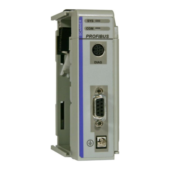
- Page 101 5.4.3 SYS and COM Status LEDs This PS69-DPM module has two bicolor status LEDs. They inform the user about the communication state of the module. The SYS LED shows the common system status of the card.
- Page 102 Contents PS69-DPM ♦ CompactLogix or MicroLogix Platform User Manual PROFIBUS DPV1 Master Behavior Significance Typical Reason Help PS69-DPM At least one slave is not in Master configuration does not Check PROFIBUS data exchange match with physical bus configuration, slave addresses...
- Page 103 PS69-DPM ♦ CompactLogix or MicroLogix Platform Contents PROFIBUS DPV1 Master User Manual 5.4.5 Cable Check that the cable is Constructing a Bus Cable for PROFIBUS DP (page 119). Check to confirm that the bus termination resistors are switched on at the beginning and the end of the cable and switched off at all other connectors in between.
- Page 104 Contents PS69-DPM ♦ CompactLogix or MicroLogix Platform User Manual PROFIBUS DPV1 Master Page 104 of 130 ProSoft Technology, Inc. October 1, 2014...
- Page 105 I/O control and messaging, thus integrating DPV0 and DPV1 functionality into CompactLogix or MicroLogix. The PS69-DPM is a CompactLogix or MicroLogix compatible, PROFIBUS certified module, which enables controllers to communicate with a PROFIBUS network. The configuration and diagnostic of the PROFIBUS system is done via the serial diagnostic interface of the module using the System Configuration tool PROSOFT.fdt (SYCON.net).
- Page 106 Contents PS69-DPM ♦ CompactLogix or MicroLogix Platform User Manual PROFIBUS DPV1 Master 6.1.2 PROFIBUS Interface Isolated RS-485 interface per EN 50170. RxD/TxD-P Receive/Send Data-P respectively connection B plug DGND Reference potential Positive power supply RxD/TxD-N Receive/Send Data-N respectively connection A plug Please ensure that termination resistors are available at both ends of the cable.
- Page 107 PS69-DPM ♦ CompactLogix or MicroLogix Platform Contents PROFIBUS DPV1 Master User Manual The maximum length of a bus segment depends on the baud rate used. Only PROFIBUS certified cable, preferably the cable type A, should be used. Baud rate in kBit/s Max.
- Page 108 Contents PS69-DPM ♦ CompactLogix or MicroLogix Platform User Manual PROFIBUS DPV1 Master Specification Description Agency Certification: C-UL certified, UL 508 listed, CE UL/CE PROFIBUS conformance certified PROFIBUS Functionality 6.2.1 DPV0 Services DPV0 services in PROFIBUS refer to the cyclic data exchange mechanism between a class 1 master and a network slave.
- Page 109 PS69-DPM ♦ CompactLogix or MicroLogix Platform Contents PROFIBUS DPV1 Master User Manual Watchdog Using the Watchdog functionality a network slave is able to monitor bus traffic in order to ensure that the network master is still active and process data sent and received are still being updated.
- Page 110 Contents PS69-DPM ♦ CompactLogix or MicroLogix Platform User Manual PROFIBUS DPV1 Master RSLogix 5000 User Defined Data Types The section contains the user defined data types created and used in the example programs. 6.3.1 Input: DPM_INPUT_ARRAY Name Data Type Description...
- Page 111 PS69-DPM ♦ CompactLogix or MicroLogix Platform Contents PROFIBUS DPV1 Master User Manual 6.3.4 Input: DPM_GLOBAL_STATE_FIELD Name Data Type Description Ctrl BOOL Control error Aclr BOOL Auto clear error Nexc BOOL Non exchange error BOOL Fatal error BOOL Event error NRdy...
- Page 112 Contents PS69-DPM ♦ CompactLogix or MicroLogix Platform User Manual PROFIBUS DPV1 Master Name Data Type Description Sta3_Reserved2 BOOL Reserved Sta3_Reserved3 BOOL Reserved Sta3_Reserved4 BOOL Reserved Sta3_Reserved5 BOOL Reserved Sta3_Reserved6 BOOL Reserved Sta3_ExtDiagOverflow BOOL Extended diagnostic overflow MasterAddress SINT Corresponding master address...
- Page 113 PS69-DPM ♦ CompactLogix or MicroLogix Platform Contents PROFIBUS DPV1 Master User Manual 6.3.8 Output: DPM_DEV_COMMAND_REGISTER Name Data Type Description Reserved0 BOOL Reserved Reserved1 BOOL Reserved Reserved2 BOOL Reserved Reserved3 BOOL Reserved Reserved4 BOOL Reserved NRdy BOOL Application Not Ready Init...
- Page 114 Contents PS69-DPM ♦ CompactLogix or MicroLogix Platform User Manual PROFIBUS DPV1 Master 6.3.11 DDLM_GLOBAL_CONTROL_REQUEST Name Data Type Description Reserved1 Reserved2 Reserved3 Command SINT Reserved4 SINT DeviceAdr SINT Device Address ConrolCommand SINT Control Command GroupSelect SINT Group Select 6.3.12 DDLM_GLOBAL_CONTROL_CONFIRM Name...
- Page 115 PS69-DPM ♦ CompactLogix or MicroLogix Platform Contents PROFIBUS DPV1 Master User Manual 6.3.15 DDLM_SLAVE_DIAGNOSTIC_REQUEST Name Data Type Description Reserved1 Reserved2 Reserved3 Command SINT Reserved4 SINT DeviceAdr SINT DataArea SINT DataAdr DataIdx SINT DataCnt SINT DataType SINT Function SINT 6.3.16 DDLM_SLAVE_DIAGNOSTIC_CONFIRM...
- Page 116 Contents PS69-DPM ♦ CompactLogix or MicroLogix Platform User Manual PROFIBUS DPV1 Master 6.3.17 DPM_DPV1_ALARM_INDICATION Name Data Type Description AlarmIndication BOOL Indicates an alarm Reserved1 BOOL Reserved2 BOOL Reserved3 BOOL Reserved4 BOOL Reserved5 BOOL Reserved6 BOOL AlarmOverrun BOOL Overflow of the modules internal alarm buffer...
- Page 117 PS69-DPM ♦ CompactLogix or MicroLogix Platform Contents PROFIBUS DPV1 Master User Manual 6.3.19 MSAC1_READ_REQUEST Name Data Type Description Reserved1 Reserved2 Reserved3 Command SINT Reserved4 SINT DeviceAdr SINT DataArea SINT DataAdr DataIdx SINT DataCnt SINT DataType SINT Function SINT 6.3.20 MSAC1_READ_CONFIRM...
- Page 118 Contents PS69-DPM ♦ CompactLogix or MicroLogix Platform User Manual PROFIBUS DPV1 Master Name Data Type Description DataArea SINT DataAdr DataIdx SINT DataCnt SINT DataType SINT Function SINT data SINT[240] 6.3.22 MSAC1_WRITE_CONFIRM Name Data Type Description Reserved1 Reserved2 Answer SINT Failure...
- Page 119 PS69-DPM ♦ CompactLogix or MicroLogix Platform Contents PROFIBUS DPV1 Master User Manual 6.3.24 MSAL1M_ALARM_CONFIRM Name Data Type Description Reserved1 Reserved2 Answer SINT Failure SINT Reserved3 SlaveAdr SINT SlotNum SINT SeqNum SINT AlarmType SINT AlarmSpec SINT Reserved4 SINT Constructing a Bus Cable for PROFIBUS DP The bus cable for connecting PROFIBUS DP devices must be constructed by the user.
- Page 120 Contents PS69-DPM ♦ CompactLogix or MicroLogix Platform User Manual PROFIBUS DPV1 Master Wrap the provided copper shielding F around the shield braiding S: PVC jacket S Braided shielding F Copper foil shielding Additional foil can be obtained from 3M. Plug the leads of the corresponding cable(s) into the terminals as shown:...
- Page 121 PS69-DPM ♦ CompactLogix or MicroLogix Platform Contents PROFIBUS DPV1 Master User Manual Attach the cables with the provided cable cleat to create a robust shielded connection and to relieve any tension as shown: PVC Jacket S Braided shielding with foil shielding C Cable cleat ...
- Page 122 Contents PS69-DPM ♦ CompactLogix or MicroLogix Platform User Manual PROFIBUS DPV1 Master This example indicates the shielding connection from the PROFIBUS cable to the FE/PE rail. Note: An equalization current can flow across a shield connected at both ends because of fluctuations in ground potential.
- Page 123 PS69-DPM ♦ CompactLogix or MicroLogix Platform Contents PROFIBUS DPV1 Master User Manual This representation shows distributed grounding with capacitive coupling. ProSoft Technology, Inc. Page 123 of 130 October 1, 2014...
- Page 124 Contents PS69-DPM ♦ CompactLogix or MicroLogix Platform User Manual PROFIBUS DPV1 Master Page 124 of 130 ProSoft Technology, Inc. October 1, 2014...
-
Page 125: Prosoft Technology End-User License Agreement
This End-User License Agreement ("EULA") is a legal agreement between you (either an individual or a single entity) and ProSoft Technology. Please read this Agreement carefully before you install the software. By installing or otherwise using the software, you accept the terms of this Agreement. -
Page 126: Limitation Of Liability
PROVISION AND IS TO BE ENFORCED AS SUCH. 7.4.1 No liability for consequential damages IN NO EVENT WILL PROSOFT TECHNOLOGY (OR ITS DEALER) BE LIABLE FOR ANY SPECIAL, INCIDENTAL, OR CONSEQUENTIAL DAMAGES BASED ON BREACH OF WARRANTY, BREACH OF CONTRACT, NEGLIGENCE, STRICT TORT, OR ANY OTHER LEGAL THEORY. - Page 127 Contacting Technical Support ..............127 Warranty Information ................128 Contacting Technical Support ProSoft Technology, Inc. is committed to providing the most efficient and effective support possible. Before calling, please gather the following information to assist in expediting this process: Product Version Number...
- Page 128 E-mail: brasil@prosoft-technology.com Languages spoken include: Portuguese, English Warranty Information For complete details regarding ProSoft Technology’s TERMS & CONDITIONS OF SALE, WARRANTY, SUPPORT, SERVICE AND RETURN MATERIAL AUTHORIZATION INSTRUCTIONS please see the documents on the ProSoft Solutions DVD or go to www.prosoft-technology/warranty.
- Page 129 CompactLogix Messaging Example • 92 GRANT OF LICENSE • 125 Configuration of PROFIBUS Slaves • 42 Configuration of the PS69-DPM Master • 39 Configure the PROFIBUS Network • 33 Configuring the RSLinx Driver for the PC COM Port • Hardware Diagnostics (LED) • 96 Hardware Requirements •...
- Page 130 Support, Service & Warranty PS69-DPM ♦ CompactLogix or MicroLogix Platform User Manual PROFIBUS DPV1 Master Module Properties 1 • 53 Slave Settings Parameter Tab • 44 Module Properties 2 • 54 SOFTWARE COPYRIGHT PRODUCT LICENSE • 125 Module Selection • 51, 55 Software Requirements •...
Need help?
Do you have a question about the PS69-DPM and is the answer not in the manual?
Questions and answers