
Subscribe to Our Youtube Channel
Related Manuals for ProSoft Technology MVI69-GEC


Summary of Contents for ProSoft Technology MVI69-GEC
- Page 1 MVI69-GEC CompactLogix or MicroLogix Platform Generic ASCII Ethernet Communication Module February 18, 2014 USER MANUAL...
-
Page 2: Your Feedback Please
® ProSoft Technology , is a registered Copyright of ProSoft Technology, Inc. All other brand or product names are or may be trademarks of, and are used to identify products and services of, their respective owners. In an effort to conserve paper, ProSoft Technology no longer includes printed manuals with our product shipments. -
Page 3: Battery Life Advisory
Warnings North America Warnings Warning - Explosion Hazard - Substitution of components may impair suitability for Class I, Division 2. Warning - Explosion Hazard - When in hazardous locations, turn off power before replacing or rewiring modules. Warning - Explosion Hazard - Do not disconnect equipment unless power has been switched off or the area is known to be non-hazardous. -
Page 4: Agency Approvals And Certifications
Agency Approvals and Certifications Agency Applicable Standard(s) ATEX EN 60079-0:2006, EN 60079-15:2005 DET NORSKE VERITAS Test 2.4 EMC-EN61326-1:2006; EN61000-6-4:2007 CB Safety CA/10533/CSA, IEC 61010-1 Ed. 2, CB 243333-2056722 (2090408) GOST-R EN 61010 ME06... - Page 5 MVI69-GEC ♦ CompactLogix or MicroLogix Platform Contents User Manual Contents Your Feedback Please ........................2 Important Installation Instructions ....................... 2 MVI (Multi Vendor Interface) Modules ....................2 Warnings ............................. 3 Battery Life Advisory ........................... 3 Markings .............................. 3 Start Here System Requirements ....................
- Page 6 Ethernet Connection ....................72 6.3.2 RS-232 Configuration/Debug Port ................72 6.3.3 DB9 to RJ45 Adaptor (Cable 14) ................75 MVI69-GEC Status Data For Block Transfer ............75 Support, Service & Warranty Contacting Technical Support ................. 83 Warranty Information ....................84 Index Page 6 of 86 ProSoft Technology, Inc.
-
Page 7: Start Here
MVI69-GEC module. The module requires 800 mA of available power. Important: The MVI69-GEC module has a power supply distance rating of 2 (L43 and L45 installations on first 2 slots of 1769 bus). -
Page 8: Package Contents
RSLogix versions will work correctly. Package Contents The following components are included with your MVI69-GEC module, and are all required for installation and configuration. Important: Before beginning the installation, please verify that all of the following items are present. - Page 9 Technology website (http://www.prosoft-technology.com). The filename contains the version of PCB. For example, PCB_4.1.0.4.0206.exe. To install ProSoft Configuration Builder from the ProSoft Technology website Open your web browser and navigate to www.prosoft-technology.com/pcb Click the link at the Current Release Version section to download the latest version of ProSoft Configuration Builder.
-
Page 10: Installing The Module
MVI69-GEC ♦ CompactLogix or MicroLogix Platform User Manual The following illustration shows the MVI69-GEC jumper configuration with the Setup Jumper OFF. Note: If you are installing the module in a remote rack, you may prefer to leave the Setup pins jumpered. That way, you can update the module’s firmware without requiring physical access to the module. - Page 11 MVI69-GEC ♦ CompactLogix or MicroLogix Platform Contents User Manual Align the module using the upper and lower tongue-and-groove slots with the adjacent module and slide forward in the direction of the arrow. Move the module back along the tongue-and-groove slots until the bus connectors on the MVI69 module and the adjacent module line up with each other.
- Page 12 Contents MVI69-GEC ♦ CompactLogix or MicroLogix Platform User Manual Push the module’s bus lever back slightly to clear the positioning tab and move it firmly to the left until it clicks. Ensure that it is locked firmly in place. Close all DIN-rail latches.
- Page 13 MVI69-GEC ♦ CompactLogix or MicroLogix Platform Contents User Manual Press the DIN-rail mounting area of the controller against the DIN-rail. The latches will momentarily open and lock into place. ProSoft Technology, Inc. Page 13 of 86 February 18, 2014...
-
Page 14: Downloading The Sample Program To The Processor
Contents MVI69-GEC ♦ CompactLogix or MicroLogix Platform User Manual Connecting Your PC to the Processor Connect the right-angle connector end of the cable to your controller at the communications port. Connect the straight connector end of the cable to the serial port on your computer. -
Page 15: Configuring The Rslinx Driver For The Pc Com Port
MVI69-GEC ♦ CompactLogix or MicroLogix Platform Contents User Manual When communication is established, RSLogix will open a confirmation dialog box. Click the D button to transfer the sample program to the processor. OWNLOAD RSLogix will compile the program and transfer it to the processor. This process may take a few minutes. - Page 16 Contents MVI69-GEC ♦ CompactLogix or MicroLogix Platform User Manual This action opens the Configure Drivers dialog box. Note: If the list of configured drivers is blank, you must first choose and configure a driver from the Available Driver Types list. The recommended driver type to choose for serial communication with the processor is RS-232 DF1 Devices.
-
Page 17: Connecting Your Pc To The Module
MVI69-GEC ♦ CompactLogix or MicroLogix Platform Contents User Manual When you see the message Auto Configuration Successful, click the OK button to dismiss the dialog box. Note: If the auto-configuration procedure fails, verify that the cables are connected correctly between the processor and the serial port on your computer, and then try again. - Page 18 Contents MVI69-GEC ♦ CompactLogix or MicroLogix Platform User Manual Page 18 of 86 ProSoft Technology, Inc. February 18, 2014...
-
Page 19: Using Prosoft Configuration Builder
MVI69-GEC ♦ CompactLogix or MicroLogix Platform Contents User Manual MVI69-GEC Configuration In This Chapter Using ProSoft Configuration Builder ............19 [Module] ....................22 [Server x] ....................22 Ethernet Configuration - MVI56E ............23 Downloading the Configuration to the Module Using Serial ....24... -
Page 20: Setting Up The Project
Contents MVI69-GEC ♦ CompactLogix or MicroLogix Platform User Manual 2.1.1 Setting Up the Project To begin, start ProSoft Configuration Builder. If you have used other Windows configuration tools before, you will find the screen layout familiar. ProSoft Configuration Builder’s window consists of a tree view on the left, an information pane and a configuration pane on the right side of the window. - Page 21 Module Type dialog box. In the Product Line Filter area of the dialog box, select MVI69. In the Select Module Type dropdown list, select MVI69-GEC, and then click OK to save your settings and return to the ProSoft Configuration Builder window.
- Page 22 Contents MVI69-GEC ♦ CompactLogix or MicroLogix Platform User Manual Click the [+] sign next to any icon to view module information and configuration options. Double-click any icon to open an Edit dialog box. To edit a parameter, select the parameter in the left pane and make your changes in the right pane.
- Page 23 MVI69-GEC ♦ CompactLogix or MicroLogix Platform Contents User Manual 2.3.4 Connection Close Type 0, 1 or 2 This coded parameter defines the personality of the server after a connection is made. If the parameter is set to 0, the socket will only be closed when a request from the client is received or the connection timeout is exceeded.
- Page 24 Contents MVI69-GEC ♦ CompactLogix or MicroLogix Platform User Manual Double-click the E icon. This action opens the Edit dialog box. THERNET ONFIGURATION Edit the values for my_ip, netmask (subnet mask) and gateway (default gateway). When you are finished editing, click OK to save your changes and return to the ProSoft Configuration Builder window.
- Page 25 MVI69-GEC ♦ CompactLogix or MicroLogix Platform Contents User Manual From the right-click shortcut menu, choose D . The OWNLOAD FROM EVICE program scans your PC for a valid com port (this may take a few seconds). When PCB finds a valid COM port, it opens the Download dialog box.
- Page 26 Contents MVI69-GEC ♦ CompactLogix or MicroLogix Platform User Manual Page 26 of 86 ProSoft Technology, Inc. February 18, 2014...
-
Page 27: Ladder Logic
Adding the Module to an Existing MicroLogix Project ......37 Ladder logic is required for the MVI69-GEC module to work. Tasks that must be handled by the ladder logic are module data transfer, special block handling, and status data receipt. - Page 28 Contents MVI69-GEC ♦ CompactLogix or MicroLogix Platform User Manual OBJECT HIERARCHY DATA TYPE GMask INT[4] Stat GECInStat PassCnt Product INT[2] INT[2] INT[2] INT[2] BlkErrs GECBlkStat Read Write Parse Server GECServerStat[5] Enabled State INT[2] Port Open Close RxOverflow TxOverflow Timeout CfgErrword...
- Page 29 MVI69-GEC ♦ CompactLogix or MicroLogix Platform Contents User Manual OBJECT HIERARCHY DATA TYPE Backplane GECBackplane LastRead LastWriteCount CurBlock UnitNumber RxLen TxServer TxCount Clients GEClientSet[5] ConnectionSetup GECClientConnection Client Spare1 ServerIP INT[4] ServicePort SwapRx SwapTx TimeOut ReadData SINT[4000] ReadDataCount ReadTotalCount WriteData SINT[4000]...
- Page 30 Contents MVI69-GEC ♦ CompactLogix or MicroLogix Platform User Manual OBJECT HIERARCHY DATA TYPE WriteCount LastWriteCount Servers GECServerSet[5] ReadData SINT[4000] ReadDataCount ReadTotalCount WriteData SINT[4000] WriteDataCount WriteTotalCount Flags GECServerFlags InitiateWriteData BOOL CloseConnection BOOL Util GECServerUtil ReadingBlocks BOOL ReadIndex WritingBlocks BOOL WriteIndex WriteData...
- Page 31 MVI69-GEC ♦ CompactLogix or MicroLogix Platform Contents User Manual This is done by declaring a variable of the data type in the Controller Tags Edit Tags dialog box. The following table describes the structure of the object. This object contains objects that define variables for the module and status data related to the module.
- Page 32 Contents MVI69-GEC ♦ CompactLogix or MicroLogix Platform User Manual Name Data Type Description Server GECServerStat[5] Status for each server Client GECClientStat[5] Status for each client Within the GECInStat objects are objects containing the status information for each server and the block transfer process. Refer to the Reference chapter for a complete listing of the data stored in this object.
- Page 33 MVI69-GEC ♦ CompactLogix or MicroLogix Platform Contents User Manual Name Data Type Description Write Number of blocks written by the module Parse Number of blocks parsed by the module Number of block transfer errors 3.1.4 GECClientStat This object stores the status information for a single client in the module. This data is received from the module in each new input image.
- Page 34 Contents MVI69-GEC ♦ CompactLogix or MicroLogix Platform User Manual The parameter will be set to a value of 3 when the connection is being closed. This operation can be initiated from either the client using the Client control word in the output image or by the server.
- Page 35 Adding the Module to an Existing CompactLogix Project Important: The MVI69-GEC module has a power supply distance rating of 2 (L43 and L45 installations on first 2 slots of 1769 bus) If you are installing and configuring the module with a CompactLogix processor, follow these steps.
- Page 36 Contents MVI69-GEC ♦ CompactLogix or MicroLogix Platform User Manual This action opens the following dialog box: Select the 1769-Module (Generic 1769 Module) from the list and click OK. Enter the Name, Description and Slot options for your application, using the values in the illustration above.
- Page 37 MVI69-GEC ♦ CompactLogix or MicroLogix Platform Contents User Manual Click OK to continue. Select the Request Packet Interval value for scanning the I/O on the module. This value represents the minimum frequency the module will handle scheduled events. This value should not be set to less than 1 millisecond.
- Page 38 Contents MVI69-GEC ♦ CompactLogix or MicroLogix Platform User Manual Double-click the I/O Configuration icon located in the Controller folder in the project tree. This action opens the I/O Configuration dialog box. On the I/O Configuration dialog box, select "Other - Requires I/O Card Type ID" at the bottom of the list in the right pane, and then double-click to open the Module dialog box.
- Page 39 MVI69-GEC ♦ CompactLogix or MicroLogix Platform Contents User Manual After completing the module setup, the I/O configuration dialog box will display the module's presence. Copy the Ladder Rungs from the sample program. Save and Downloading the Sample Program to the Processor (page 14) the new application to the controller and place the processor in run mode.
- Page 40 Contents MVI69-GEC ♦ CompactLogix or MicroLogix Platform User Manual Page 40 of 86 ProSoft Technology, Inc. February 18, 2014...
-
Page 41: Diagnostics And Troubleshooting
MVI69-GEC ♦ CompactLogix or MicroLogix Platform Contents User Manual Diagnostics and Troubleshooting In This Chapter LED Status Indicators ................41 Using ProSoft Configuration Builder (PCB) for Diagnostics ....43 Reading Status Data from the Module ...........51 The module provides information on diagnostics and troubleshooting in the following forms: ... -
Page 42: Ethernet Led Indicators
Verify correct configuration data is being transferred to the module from the CompactLogix or MicroLogix controller. If the module's OK LED does not turn GREEN, verify that the module is inserted completely into the rack. If this does not cure the problem, contact ProSoft Technology Technical Support. 4.1.3 Troubleshooting Use the following troubleshooting steps if you encounter problems when the module is powered up. - Page 43 The module has a power supply distance rating of 2 on CompactLogix, meaning that there must not be more than one other module between the MVI69-GEC module and the power supply. If the module is used in a MicroLogix system, verify that the backplane can supply the 800 mA required by the module.
- Page 44 Contents MVI69-GEC ♦ CompactLogix or MicroLogix Platform User Manual On the shortcut menu, choose D IAGNOSTICS This action opens the Diagnostics dialog box. Press [?] to open the Main menu. Important: The illustrations of configuration/debug menus in this section are intended as a general guide, and may not exactly match the configuration/debug menus in your own module.
- Page 45 On computers with more than one serial port, verify that your communication program is connected to the same port that is connected to the module. If you are still not able to establish a connection, contact ProSoft Technology for assistance. 4.2.2 Navigation All of the submenus in ProSoft Configuration Builder for this module contain commands to redisplay the menu or return to the previous menu.
- Page 46 Use these commands only if you fully understand their potential effects, or if you are specifically directed to do so by ProSoft Technology Technical Support staff. Some of these command keys are not listed on the menu, but are active nevertheless. Please be careful when pressing keys so that you do not accidentally execute an unwanted command.
- Page 47 MVI69-GEC ♦ CompactLogix or MicroLogix Platform Contents User Manual Tip: Repeat this command at one-second intervals to determine the number of blocks transferred each second. Viewing Module Configuration Press [C] to view the Module Configuration screen. Use this command to display the current configuration and statistics for the module.
- Page 48 Use these commands only if you fully understand their potential effects, or if you are specifically directed to do so by ProSoft Technology Technical Support staff. Some of these command keys are not listed on the menu, but are active nevertheless. Please be careful when pressing keys so that you do not accidentally execute an unwanted command.
-
Page 49: Exiting The Program
Use these commands only if you fully understand their potential effects, or if you are specifically directed to do so by ProSoft Technology Technical Support staff. Some of these command keys are not listed on the menu, but are active nevertheless. Please be careful when pressing keys so that you do not accidentally execute an unwanted command. - Page 50 Contents MVI69-GEC ♦ CompactLogix or MicroLogix Platform User Manual Press [ESC] to restart the module and force all drivers to be loaded. The module will use the configuration stored in the module's flash memory to configure the module. 4.2.4 Network Menu From the Main menu press [@] to display the Network menu screen.
- Page 51 MVI69-GEC ♦ CompactLogix or MicroLogix Platform Contents User Manual Viewing the WATTCP.CFG File on the module ress [V] to view the module’s WATTCP.CFG file. Use this command to confirm the module’s current network settings. Returning to the Main Menu Press [M] to return to the Main menu.
- Page 52 Contents MVI69-GEC ♦ CompactLogix or MicroLogix Platform User Manual Page 52 of 86 ProSoft Technology, Inc. February 18, 2014...
- Page 53 Receiving ASCII Data ................53 Sending ASCII Data Use the following steps to configure the MVI69-GEC as a client to send an ASCII string to a remote device (server). The MVI69-GEC can simultaneously connect and send data to up to five servers.
- Page 54 OTAL OUNT 5.2.2 Receiving ASCII Text as a Server When a server port of the MVI69-GEC is set up, it will accept incoming ASCII text from a client only. When the MVI69-GEC receives an ASCII string from a client, the GEC.S...
-
Page 55: Product Specifications
Five servers and Clients are present on the module permitting both the reception and transmission of data between the Rockwell Automation processor and attached devices. The MVI69-GEC module is a powerful communication interface for CompactLogix or MicroLogix processors. Developed under license from Rockwell Automation, the module incorporates proprietary backplane technology that enables powerful data access between the module and the CompactLogix or MicroLogix processor. - Page 56 Contents MVI69-GEC ♦ CompactLogix or MicroLogix Platform User Manual Specification Description Storage Temp. -40°C to 85°C (-40°F to 185°F) Relative Humidity 5% to 95% (with no condensation) LED Indicators Power and Module Status Application Status CFG Port Activity Ethernet Port Activity...
- Page 57 MVI69-GEC ♦ CompactLogix or MicroLogix Platform Contents User Manual Module status Port error status word (bitmapped) Port receive state Port receive character count Port receive block count Port transmit state Port transmit character count Port transmit block count All data related to the module is contained in a single controller tag with defined objects to simplify configuration, monitoring, and interfacing with the module ...
-
Page 58: Backplane Data Transfer
Backplane Data Transfer The MVI69-GEC module communicates directly over the CompactLogix or MicroLogix backplane. Data travels between the module and the processor across the backplane using the module's input and output images. The update frequency of the data is determined by the scan rate defined by the user for the module and the communication load on the module. -
Page 59: Normal Data Transfer
MVI69-GEC ♦ CompactLogix or MicroLogix Platform Contents User Manual The following illustration shows the data transfer method used to move data between the processor, the MVI69-GEC module, and the Ethernet network. CompactLogix Processor MVI69-GEC Module Controller Tags Ladder logic Status transfers data from Module’s... - Page 60 Contents MVI69-GEC ♦ CompactLogix or MicroLogix Platform User Manual Word Description Offset Received Server Number for data received. If the word contains a value of -1, -2, Data -3 or -4, no receive data is present and the block contains status data. If the word contains a value from 0 to 4, the block contains data from one of the servers in the module.
- Page 61 MVI69-GEC ♦ CompactLogix or MicroLogix Platform Contents User Manual Object In Block Offset Description GECInStat Start Server Index For this status data block, this word is set to a value of -1. PassCnt Program cycle counter Product Product name as ASCII string...
- Page 62 Contents MVI69-GEC ♦ CompactLogix or MicroLogix Platform User Manual Object In Block Offset Description GECInStat Start Server[1].Port This word value contains the port address for the client connected to the server. Server[1].Open This status value contains the total number of times the server performed an open operation.
- Page 63 MVI69-GEC ♦ CompactLogix or MicroLogix Platform Contents User Manual Object In Block Offset Description GECInStat Start Server[2].CfgErrWord 56 This bit mapped word defines the configuration errors for the server. Reserved 57 to 62 This data area is reserved for future use.
- Page 64 Contents MVI69-GEC ♦ CompactLogix or MicroLogix Platform User Manual Object In GECInStat Block Description Offset Start Server[3].Timeout This status value contains the total number of times a connection timeout occurred on the socket. Server[3].CfgErrWord This bit mapped word defines the configuration errors for the server.
- Page 65 MVI69-GEC ♦ CompactLogix or MicroLogix Platform Contents User Manual Parameter Block Description Offset Start Operating system level as ASCII string Run number as ASCII string BlkErrs.Read Number of blocks transferred from module to processor BlkErrs.Write Number of blocks transferred from processor to module BlkErrs.Parse...
- Page 66 Contents MVI69-GEC ♦ CompactLogix or MicroLogix Platform User Manual Parameter Block Description Offset Start Client[2].Connected This flag defines if the client is utilized and connected to a server. A value of 0 indicates the client is not connected and can be utilized for a connection. Any other value indicates the client is connected and being used.
- Page 67 MVI69-GEC ♦ CompactLogix or MicroLogix Platform Contents User Manual Parameter Block Description Offset Start Client[3].State This flag defines the current state of the client. Client[3].IP This double-word value contains the IP address of the server connected to the client. Client[3].Port This word value contains the port address for the server connected to the client.
- Page 68 Contents MVI69-GEC ♦ CompactLogix or MicroLogix Platform User Manual Word Description Offset Block Sequence Number (Read block number as set by module) Transmit Server Number for data to transmit. If the word contains a value of -1, no Data transmit data is present. If the word contains a value from 0 to maximum number of servers -1, the block contains data to send to the specified server in the module.
- Page 69 The Module/Client control word contains a value of -100 for this special block. Handling Multiple Blocks An important concept to understand about the MVI69-GEC module is how multiple blocks are handled. The buffer size supports 4096 bytes (2048 words), but the module can only send 110 bytes (55 words) at each scan to the processor.
- Page 70 In order for data to be transferred between the module and another device, a TCP/IP connection must be made between a client and a server on the module. The MVI69-GEC module contains five servers that listen on the user assigned service ports waiting for a connection.
-
Page 71: Cable Connections
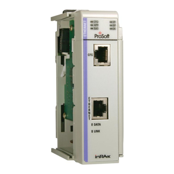
(send a message with the Reset Flag set to the client). Most applications will have the client close the socket. Cable Connections The MVI69-GEC module has the following functional communication connections installed: One Ethernet port (RJ45 connector) ... -
Page 72: Ethernet Connection
User Manual 6.3.1 Ethernet Connection The MVI69-GEC module has an RJ45 port located on the front of the module, labeled Ethernet, for use with the TCP/IP network. The module is connected to the Ethernet network using an Ethernet cable between the module’s Ethernet port and an Ethernet switch or hub. - Page 73 MVI69-GEC ♦ CompactLogix or MicroLogix Platform Contents User Manual Disabling the RSLinx Driver for the Com Port on the PC The communication port driver in RSLinx can occasionally prevent other applications from using the PC’s COM port. If you are not able to connect to the module’s configuration/debug port using ProSoft Configuration Builder (PCB), HyperTerminal or another terminal emulator, follow these steps to disable the RSLinx driver.
- Page 74 Contents MVI69-GEC ♦ CompactLogix or MicroLogix Platform User Manual You may see something like this: If you see the status as running, you will not be able to use this com port for anything other than communication to the processor. To stop the driver press the S...
-
Page 75: Db9 To Rj45 Adaptor (Cable 14)
MVI69-GEC ♦ CompactLogix or MicroLogix Platform Contents User Manual 6.3.3 DB9 to RJ45 Adaptor (Cable 14) MVI69-GEC Status Data For Block Transfer If word 1 of the Input Image block is set to -1, the data for the first three servers, the product and block transfer data is sent in the block. - Page 76 Contents MVI69-GEC ♦ CompactLogix or MicroLogix Platform User Manual Parameter Block Description Offset Start Server[0].Port This word value contains the port address for the client connected to the server. Server[0].Open This status value contains the total number of times the server performed an open operation.
- Page 77 MVI69-GEC ♦ CompactLogix or MicroLogix Platform Contents User Manual Parameter Block Description Offset Start Server[1].Timeout This status value contains the total number of times a connection timeout occurred on the socket. Server[1].CfgErrWord This bit mapped word defines the configuration errors for the server.
- Page 78 Contents MVI69-GEC ♦ CompactLogix or MicroLogix Platform User Manual Parameter Block Description Offset Start Revision level as ASCII string Operating system level as ASCII string Run number as ASCII string BlkErrs.Read Number of blocks transferred from module to processor BlkErrs.Write Number of blocks transferred from processor to module BlkErrs.Parse...
- Page 79 MVI69-GEC ♦ CompactLogix or MicroLogix Platform Contents User Manual Parameter Block Description Offset Start Server[4].Established This status value contains the total number of times a connection was established on the socket. Server[4].Closed This status value contains the total number of times a close operation was performed on the socket.
- Page 80 Contents MVI69-GEC ♦ CompactLogix or MicroLogix Platform User Manual Parameter Block Offset Description Start Client[0].Port This word value contains the port address for the server connected to the client. Client[0].RxCount This status value contains the total number of messages received by the client.
- Page 81 MVI69-GEC ♦ CompactLogix or MicroLogix Platform Contents User Manual Parameter Block Offset Description Start Client[2].TxCount This status value contains the total number of messages transmitted by the client. Client[2].TxOverflow This status value contains the total number of transmit messages that exceeded the specified maximum buffer size for the client.
- Page 82 Contents MVI69-GEC ♦ CompactLogix or MicroLogix Platform User Manual Parameter Block Offset Description Start Client[3].spare Reserved for future use Client[4].Connected This flag defines if the client is utilized and connected to a server. A value of 0 indicates the client is not connected and can be utilized for a connection.
-
Page 83: Support, Service & Warranty
Contacting Technical Support ..............83 Warranty Information ................84 Contacting Technical Support ProSoft Technology, Inc. is committed to providing the most efficient and effective support possible. Before calling, please gather the following information to assist in expediting this process: Product Version Number... -
Page 84: Warranty Information
E-mail: brasil@prosoft-technology.com Languages spoken include: Portuguese, English Warranty Information For complete details regarding ProSoft Technology’s TERMS & CONDITIONS OF SALE, WARRANTY, SUPPORT, SERVICE AND RETURN MATERIAL AUTHORIZATION INSTRUCTIONS please see the documents on the Product DVD or go to www.prosoft-... - Page 85 Module Power Up • 57 MVI (Multi Vendor Interface) Modules • 2 MVI69-GEC Configuration • 19 MVI69-GEC Status Data For Block Transfer • 75 DB9 to RJ45 Adaptor (Cable 14) • 75 Diagnostics and Troubleshooting • 39, 41, 72 Disabling the RSLinx Driver for the Com Port on the PC •...
- Page 86 Support, Service & Warranty MVI69-GEC ♦ CompactLogix or MicroLogix Platform User Manual Receiving ASCII Data • 53 Receiving ASCII Text as a Client • 54 Your Feedback Please • 2 Receiving ASCII Text as a Server • 54 Redisplaying the Menu • 46 Reference •...
Need help?
Do you have a question about the MVI69-GEC and is the answer not in the manual?
Questions and answers