Table of Contents
Advertisement
Quick Links
Advertisement
Table of Contents
Troubleshooting

Related Manuals for Konica Minolta CM-M6


Summary of Contents for Konica Minolta CM-M6
- Page 1 Instruction Manual Please read before using the instrument.
- Page 2 (Official name) Bluetooth Bluetooth® Trademarks • The Bluetooth® mark and logo are registered trademarks of The Bluetooth SIG, Inc. and are used under license. • The KONICA MINOLTA logo and symbol marks and SpectraMagic are registered trademarks of Konica Minolta, Inc.
-
Page 3: Safety Symbols
Notes on this Manual „ „ • Copying or reproduction of all or part of the contents of this manual without the permission of KONICA MINOLTA is strictly prohibited. • The contents of this manual are subject to change without prior notice. - Page 4 100-240 VAC (50/60 Hz) AC outlet of the rated voltage and frequency. If an AC adapter other than those specified by KONICA MINOLTA is used, or if the adapter is connected to an unsupported voltage, it may result in damage to the adapter, fire, or electric shock. To use the instrument outside the area of purchase, please contact a KONICA MINOLTA-authorized service facility.
- Page 5 Do not touch the lithium-ion battery with wet hands. Doing so may result in electric shock or a malfunction. Use the dedicated charger to charge the lithium-ion battery. If charging conditions or a charger different from that specified is used for charging, the battery may leak, overheat, or catch fire. Always hold the plug itself when disconnecting the cable from an outlet.
-
Page 6: Introduction
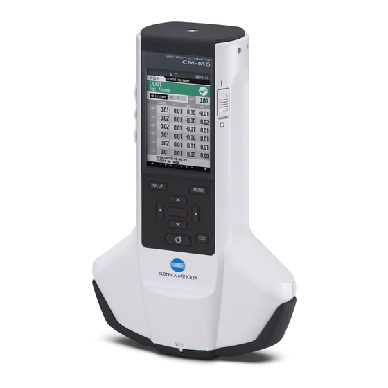
Introduction The CM-M6 is a multi-angle spectrophotometer capable of measuring from six angles in a single measurement. Please read this manual carefully before using the instrument. Packing materials of the product Be sure to keep all packing materials used for shipping the instrument (cardboard box, cushioning material, plastic bags, etc.). - Page 7 • Do not attempt to replace the built-in backup battery. The battery should only be replaced by KONICA MINOLTA. To replace the backup battery, please contact a KONICA MINOLTA-authorized service facility. • It is recommended to manage important data using the optional SpectraMagic DX software.
-
Page 8: X84; „ Notes On Storage
• If you are unable to remove dirt from the instrument through the above procedure, or if the instrument becomes scratched, contact a KONICA MINOLTA-authorized service facility. • If you are unable to remove dirt from the instrument or if the instrument becomes scratched, contact a KONICA MINOLTA-authorized service facility. -
Page 9: Disposal Method
Disposal Method „ „ • Make sure that the instrument, all accessories (including any used batteries), and the packing materials are either disposed of or recycled correctly in accordance with local laws and regulations. • In the United States and Canada, you can recycle your lithium-ion battery through the Call2Recycle program. For more information, in the United States visit www.call2recycle.org and in Canada visit www.call2recycle.ca. -
Page 10: Table Of Contents
Table of Contents Chapter 2 Measurement ....30 Safety Symbols ..........ii „ „ Notes on this Manual ........ii „ „ Flow of Measurement ........31 Introduction .............3 Calibration .............32 Notes on Use ............ 3 „ „ Zero Calibration ..........32 „ „... - Page 11 Measurement Option Settings ....... 67 Connecting to a Printer ........ 108 „ „ „ „ Measurement Angle ........68 Connecting via USB Cable ....... 108 … „ … „ Auto Average (1 to 10) ....... 69 Connecting via Bluetooth ......109 …...
-
Page 12: Conventions
Conventions „ „ This manual describes how to safely operate the CM-M6 using a specific procedure to perform measurement. · Viewing Pages Symbols used in this manual are explained below. * Explanatory pages are constructed as follows. (The content of the explanatory illustration will differ from the actual page.) -
Page 13: Chapter 1 Before Using The Instrument
Chapter Before Using the Instrument Accessories ............11 Standard Accessories ..........11 Optional Accessories ..........12 System Diagram ...........14 Names and Functions of Parts .......15 Handling the Instrument ........17 White Calibration Cap ..........20 Zero Calibration Box ..........21 Cleaning Parts ............24 Instrument Operation/Display ........26 Data Saving .............29... -
Page 14: Accessories
Accessories Standard and optional accessories are available with the instrument. The shape of some products may be different from those shown. Memo *Not available in all areas. Standard Accessories „ „ AC Adapter AC-A311* Used to supply power from an AC outlet to the instrument. Input: 100 to 240 V 50/60 Hz 31 to 43 VA 0.31 to 0.18 A Output: 11 V... -
Page 15: X84; „ Optional Accessories
Zero Calibration Box CM-A222 Used to perform zero calibration. Optional Accessories „ „ Hard Case CM-A221 Used for carrying the instrument and accessories by hand. Lithium-Ion Battery (spare) CM-A223* This battery is a replacement for the standard lithium-ion battery. Bluetooth Module CM-A219* Used for establishing wireless communication and transferring data between the instrument and a PC or a printer. - Page 16 Battery Charger CM-A227* Used as the dedicated charger to charge the lithium-ion battery. The battery charger must be connected to the AC adapter (AC- A311) supplied with the instrument for use. Color Plates (White, black, and 12 other colors) Used for simple diagnosis of instrument measurement performance (instrumental errors and repeatability).
-
Page 17: System Diagram
Bluetooth Module Set CM-A264** Battery Charger Bluetooth Module CM-A227* CM-A219* Hand Strap CM-A220 Cable Set for Bluetooth Module Spectrophotometer CM-A225** CM-M6 Lithium-Ion Battery (spare) White Calibration Cap CM-A223* CM-A226 Bluetooth Adapter (commercially available) Bluetooth Printer (commercially available) USB Cable (commercially... -
Page 18: Names And Functions Of Parts
Names and Functions of Parts... - Page 19 1 Power switch Used to turn ON/OFF power. Sliding the switch turns the power ON or OFF. 2 Hand strap attachment hole Used to attach the hand strap. 3 Measurement key Press to calibrate or measure. Measurement can also be performed by pressing the measurement button (10).
-
Page 20: Handling The Instrument
Handling the Instrument Attaching the Hand Strap … „ Do not put a load on the hand strap such as by swinging the instrument or moving the instrument by the strap. Notes Doing so may cause the strap to become detached, allowing the instrument to fall and become damaged. Pass one end of the hand strap through the hand strap attachment hole. -
Page 21: Inserting/Removing The Battery
Inserting/Removing the Battery … „ This instrument uses a dedicated lithium-ion battery (CM-A234) as the battery. Use the battery as needed for the application. CAUTION • Remove the battery if the instrument will not be used for at least 2 weeks. If the battery is left in the instrument for long periods, the battery may leak and damage the instrument. -
Page 22: X85; „ Connecting The Ac Adapter
Removing the Battery Turn the power OFF. Open the battery compartment cover located on the back of the instrument. While pressing the protrusion marked in the diagram, slide the battery in the direction of the arrow. Lift up the battery to remove it. Connecting the AC Adapter …... -
Page 23: White Calibration Cap
White Calibration Cap „ „ The white calibration cap is attached the instrument when performing white calibration. • Make sure the white calibration cap being used includes the same serial No. as that of the instrument being Notes used. • When the white calibration cap is not in use, keep the white calibration plate away from external light and dust by taking such measures as placing the cap pointed downward. -
Page 24: Zero Calibration Box
Zero Calibration Box „ „ The zero calibration box is used to perform zero calibration. Zero calibration hole White calibration cap attachment area Attaching to/Removing from Instrument … „ Attaching the Zero Calibration Box Hold the instrument securely. Align the specimen measuring port on the MENU instrument with the hole of the zero calibration box, and place the instrument on the zero calibration box... -
Page 25: Attaching/Removing The White Calibration Cap To/From The Zero Calibration Box
Attaching/Removing the White Calibration Cap to/from the Zero … „ Calibration Box The white calibration cap can be attached to the zero calibration box for use as a set. Attaching the White Calibration Cap Open the zero calibration box as shown in the diagram. Place the white calibration cap so that the white calibration plate is facing downward, align the screw holes for mounting the white calibration cap... - Page 26 Removing the White Calibration Cap Open the zero calibration box. Release the screws holding the white calibration cap in place in the zero calibration box. Re-assemble the zero calibration box.
-
Page 27: Cleaning Parts
Cleaning Parts „ „ This section explains how to clean the white calibration plate and zero calibration box. White Calibration Cap (Standard Accessories) … „ • When a white calibration plate becomes dirty, gently wipe White calibration plate the dirt off with a soft dry cloth. If the dirt is difficult to remove, wipe it off with a cloth dampened with commercially available lens cleaning solution. -
Page 28: Turning The Power On/Off
Turning the Power ON/OFF … „ Operating Procedure Turning the Power ON Slide the power switch to the “|” side. The power will turn ON. • When first turning the instrument ON after Notes purchasing, the language setting screen will be displayed, followed by the date and time setting screen. -
Page 29: Display Language
Display Language … „ When first turning the instrument ON after purchasing, the language setting screen will be displayed. Please select the language. The display language can be selected from 11 languages including English. For details, refer to page 89 “Display Language Settings”. The language selection screen can also be displayed by turning ON the instrument while holding down [MENU]. -
Page 30: Status Bar Icons
Status Bar Icons … „ Display Description (Status) Meaning Direction Double Path (Dual directions) / Single Path (Left) Equipment diagnosis result Pass / Warning / No diagnosis /None Protect target data Changes or deletion of target data allowed / /None prohibited Flash status Flash ready / Insufficient light... -
Page 31: Control Keys
Control Keys … „ Use these keys to set items or change screens according to the guide on the LCD screen. MENU Switches between the <Target> screen and <Sample> screen. (Target/Sample) key 2 [MENU] key Displays the <Settings> screen. 3 [, , , ] keys Switches screen tabs from the <Result>... -
Page 32: Data Saving
Data Saving „ „ Data used with this instrument are saved automatically within the instrument. This instrument can store data for up to 200 targets and 800 measurements. Data on the instrument can also be imported to a PC using the optional Color Data Software “SpectraMagic DX”. -
Page 33: Chapter 2 Measurement
Chapter Measurement Flow of Measurement ...........31 Calibration ............32 Zero Calibration ............32 White Calibration ............34 Measurement ............36 Average Measurement ..........37 Measurement (Color Difference) ......38 Target Setting ............38 Checking Color Differences ........38 Pass/Fail Judgment for Color Difference ....39 Pass/Fail Judgment Based on Tolerances ....39 Measurement/Data Display Screen ......42... -
Page 34: Flow Of Measurement
Flow of Measurement Optional Settings Basic Procedure „ „ Turning the Power ON (Page 25) * As necessary, such as when the power is Language selection (Page 89) first turned ON Measurement condition settings (Page 66) Zero calibration (Page 32) *Only when required ... -
Page 35: Calibration
Calibration The following two types of calibration can be performed with this instrument. • White calibration : The reflectance is measured in advance using a known white calibration plate in order to provide a reflectance scale. • Zero calibration : Only the amount of stray light is measured with the zero calibration box in advance in order to eliminate the effects of the stray light. - Page 36 Set the instrument on the zero calibration box while referring to page 21 “Zero Calibration Box”. Calibration Please set the instrument on the zero calibration box and press the measurement button. Press the measurement key or the measurement button. Zero calibration will be performed. Calibration When the zero calibration is completed, a screen prompting white calibration is displayed.
-
Page 37: White Calibration
White Calibration „ „ This instrument requires white calibration before performing measurement after the power is turned ON and before performing measurement for the first time. • If the calibration interval is turned ON and a time is configured, a message prompting white calibration will be Memo displayed the next time the power is turned ON only after the set time has passed since the previous white calibration. - Page 38 Press the measurement key or the measurement button. White calibration will be performed. Calibration CALIBRATION Calibrating to white After white calibration is complete, the display will return to the <Calibration> screen.
-
Page 39: Measurement
Measurement • Prior to the start of measurement, be sure to perform white calibration. For details, refer to “White Notes Calibration” on page 34. • To display the color difference, target colors must be set before measurement. • To measure a target, select the target number before measurement. • For accurate measurement, make sure to keep measurement conditions (ambient temperature, etc.) constant. -
Page 40: Average Measurement
Average Measurement „ „ Averaging measurement can be performed automatically or manually. With auto averaging, the sample is measured multiple times at the same position and the average is calculated. This improves the accuracy of the sample data. Manual averaging is used when the color of the sample is not uniform. Measurements are performed at different positions and the average is calculated. -
Page 41: Measurement (Color Difference)
Measurement (Color Difference) Target Setting „ „ To calculate the color difference between two samples, set one of the samples as the target, and then measure the other sample. This instrument can store data for up to 200 targets. • Target data is stored with setting numbers from 0001 to 0200 being assigned. Even when the data at some point is Memo deleted, these setting numbers do not change. -
Page 42: Pass/Fail Judgment For Color Difference
Pass/Fail Judgment for Color Difference With this instrument, tolerances can be set for the color difference of the sample data from the target color data to perform judgment. For the procedure on setting tolerances, refer to page 55 “Tolerance Settings” and page 81 “Default Tolerance Setting”. - Page 43 <Sample> Display Screen If no relevant target data has been set, no color difference value or pass/fail mark will be displayed. Notes Display when no sample and target color difference exceeds the warning value (without exceeding the tolerance) Absolute value, Difference, Abs. & Diff., and Custom screens Ex.: Abs.
-
Page 44: Changing Screens
Changing Screens … „... -
Page 45: Measurement/Data Display Screen
Measurement/Data Display Screen „ „ Target List Screen • For every data entry, the target No. and name is displayed in the column above, and the measurement date and time are displayed in the column below. • The cursor will appear at the currently selected target. • Press the [Confirmation] key or [ESC] to bring up the target detail screen and display the currently selected target’s detailed data. - Page 46 Sample List Screen • If the data does not exist, the measurement list screen will not be displayed. • For every data entry, the sample No. and name is displayed in the column above, and the measurement date and time are displayed in the column below. • The cursor will appear at the currently selected sample.
-
Page 47: Chapter 3 Environment Settings/Other Settings
Chapter Environment Settings/ Other Settings Menus ..............45 Color Difference Target Color Operation ....47 Print ................48 Edit Name ...............49 Target Data Management ........50 Pass/Fail ..............54 Handling the Sample ..........58 Print ................59 Edit Name ...............60 Sample Data Management........61 Measurement Condition Settings......66 Measurement Condition Settings......66 Measurement Option Settings .........67 Display Condition Settings ........72 Display Settings ............75... -
Page 48: Menus
Menus „ „ The instrument’s menu structure is as shown below. Target menu Measurement cond. Print data P.48 Measurement setup Measurement angle P.68 Edit name P.49 -15°, 15°, 25°, 45°, 75°, 110° Data management Auto average P.69 Delete data P.50 1 to 10 Times OK/Cancel Manual average... - Page 49 Setting Beep P.94 Default data setup P.80 OFF/ON Default tolerance P.81 OK/Cancel Measurement button P.95 OFF/ON Warning level P.82 0 to 100% Power saving P.96 00 to 60 (minute) Parametric coef. P.82 l (CMC), c (CMC), l (ΔE*94), Diagnosis info. P.97 c (ΔE*94), h (ΔE*94), Diagnosis info.
-
Page 50: Color Difference Target Color Operation
Color Difference Target Color Operation The <Target menu> screen allows the following operations for target color data. <Print data> Print the current target color data with the printer. <Edit name> Name the target data. <Data management> • Delete data : Delete the selected target color data. • Change list position : Jump to the specified target color data. • Protect data : Protects all target color data. New measurements are still possible. -
Page 51: Print
Print „ „ Print the target color data. The instrument must be connected to the serial printer in advance. For instructions on how to connect the instrument to a serial printer, refer to page 108 “Connecting to a Printer”. • If a proper connection is not established, printing will not be possible. Notes • Even if the connection has been correctly established, printing may fail for reasons such as the printer being turned off when printing is attempted. -
Page 52: Edit Name
Edit Name „ „ Name the target color data. Operating Procedure Start the procedure from the <Target menu> screen. Use [] or [] to move the cursor to “Edit name”, Target and then press the [Confirmation] key. The <Edit name> screen is displayed. Target menu [0011] Print data Edit name... -
Page 53: Target Data Management
Target Data Management „ „ Target data management allows users to delete target data, change list positions, protect data, and delete all data. Operating Procedure Start the procedure from the <Target menu> screen. Use [] or [] to move the cursor to “Data management”, and then press the [Confirmation] key to display the <Data management>... -
Page 54: Change List Position
Change List Position … „ Specifying target numbers allows for specified targets to be displayed without the need to scroll the screen. Operating Procedure Start the procedure from the <Target menu> - <Data management> screen. Use [] or [] to move the cursor to “Change list Target position”, and then press the [Confirmation] key. -
Page 55: Protect Data
Protect Data … „ Data protection can be specified so that the saved target color settings will not be deleted or changed by accident. When the data protection is set, you cannot select “Edit name”, “Edit tolerance”, “Delete data” or “Delete all data” on the <Target menu>... -
Page 56: Delete All Data
Delete All Data … „ Delete all the target color data that have been set. When the data is protected, “Delete all data” cannot be selected on the <Data management> screen. Notes Operating Procedure Start the procedure from the <Target menu> - <Data management> screen. Use [] or [] to move the cursor to “Delete all Sample data”, and then press the [Confirmation] key. -
Page 57: Pass/Fail
Pass/Fail „ „ Edit the tolerance that will be used as the judgment criteria, and set the warning level and the parametric coefficient default value. If the color difference between the sample and the target exceeds the tolerance, the column of the display color value relevant to the measurement display will be displayed in red. -
Page 58: Tolerance Settings
Tolerance Settings … „ Specify the tolerance used for pass/fail judgment of measured data for each target color. Operating Procedure Start the procedure from the <Target menu> - <Pass/Fail> screen. Use [] or [] to move the cursor to “Edit Target tolerance”, and then press the [Confirmation] key. -
Page 59: Warning Level Setting
Warning Level Setting … „ Warnings are displayed when measurement data nears the tolerance. Users can set how close to the tolerance the data must be before a warning occurs. Operating Procedure Start the procedure from the <Target menu> - <Pass/Fail> screen. Use [] or [] to move the cursor to “Warning Target level”, and then press the [Confirmation] key. -
Page 60: Parametric Coefficient Setting
Parametric Coefficient Setting … „ Specify the parametric coefficient used for pass/fail judgment of measured data for each target color. Parametric coefficients can be edited only when the difference equation is “CMC”, “ΔE*94”, or “ΔE00”. Memo Operating Procedure Start the procedure from the <Target menu> - <Pass/Fail> screen. Use [] or [] to move the cursor to “Parametric Target coef.”, and then press the [Confirmation] key. -
Page 61: Handling The Sample
Handling the Sample <Screen transition> The keys can be used to switch between screens displaying the data. On the <Sample menu> screen, the following operations are available for the measurement data. <Print data> Print the current sample data with the printer. <Edit name>... -
Page 62: Print
Print „ „ This function can be used to print measurement data. The instrument must be connected to the serial printer in advance. For instructions on how to connect the instrument to a serial printer, refer to page 108 “Connecting to a Printer”. -
Page 63: Edit Name
Edit Name „ „ Name the sample data. Display the name of the sample to be edited on the <Sample> screen in advance. Setting Procedure Start the procedure from the <Sample menu> screen. Use [] or [] to move the cursor to “Edit name”, Sample and then press the [Confirmation] key. -
Page 64: Sample Data Management
Sample Data Management „ „ Sample data management allows users to delete measurement data, copy the sample to the target, change the link to the target, change the list position, and delete all data. Setting Procedure Start the procedure from the <Sample menu> screen. Use [] or [] to move the cursor to “Data management”, and then press the [Confirmation] key to display the <Data management>... -
Page 65: Setting Measurement Data As Target
Setting Measurement Data as Target … „ Set the measurement data as the target data. Display the sample to be set as the target on the <Sample> screen in advance. Setting Procedure Start the procedure from the <Sample menu> - <Data management> screen. • Target colors are stored with setting numbers from 0001 to 0200 being assigned. -
Page 66: Change Target Reference
Change Target Reference … „ This section describes how to change the target data selection. Display the sample for which the target reference is to be changed on the <Sample> screen in advance. Setting Procedure Start the procedure from the <Sample menu> - <Data management> screen. Use [] or [] to move the cursor to “Change Sample Target reference”, and then press the [Confirmation]... -
Page 67: Change List Position
Change List Position … „ Specifying sample numbers allows for specified sample to be selected without the need to scroll the screen. Setting Procedure Start the procedure from the <Sample menu> - <Data management> screen. Use [] or [] to move the cursor to “Change list Sample position”, and then press the [Confirmation] key. -
Page 68: Delete All Data
Delete All Data … „ Delete all measurement data. Setting Procedure Start the procedure from the <Sample menu> - <Data management> screen. Use [] or [] to move the cursor to “Delete all Sample data”, and then press the [Confirmation] key. 0002 TARGET-2 The <Delete all data>... -
Page 69: Measurement Condition Settings
Measurement Condition Settings This instrument requires measurement condition settings (average count, observer/illuminant, and display) to be configured before measurement can be started. Measurement Condition Settings „ „ To set measurement conditions, select the setting from the <Measurement cond.> menu. The following three items can be specified as the measurement conditions: • Measurement setup : S ets the measurement angle, number of auto average or manual average measurements... -
Page 70: Measurement Option Settings
Measurement Option Settings „ „ To set measurement options, select “Measurement setup” from the <Measurement cond.> menu screen. Select or specify the following items as the measurement options: • Measurement angle (-15°, 15°, 25°, 45°, 75°, 110°) : Specify the measurements angle. • Auto average (1 to 10) : Specify the number of measurements for auto averaging. -
Page 71: Measurement Angle
Measurement Angle … „ Select the measurement angle. All six measurement angles are set under the initial settings. Memo Operating Procedure Start the procedure from the <Measurement cond.> - <Measurement setup> screen. Use [] or [] to move the cursor to “Measurement Sample angle”, and then press the [Confirmation] key. -
Page 72: Auto Average (1 To 10)
Auto Average (1 to 10) … „ Specify the number of measurements for auto averaging. Every time the measurement key/button is pressed, the average of the data obtained from the specified number of continuous measurements is determined as sample data. “1 Times”... -
Page 73: Manual Average (1 To 10)
Manual Average (1 to 10) … „ Specify the number of measurements for manual averaging. The average of the data obtained from the measurements conducted by pressing the measurement button the specified number of times is determined as sample data. “1 Times”... -
Page 74: Manual Average Option
Manual Average Option … … Select the save method when performing manual averaging. Operating Procedure Start the procedure from the <Measurement cond.> - <Measurement setup> screen. Use [] or [] to move the cursor to “Manual average option”, and then press the [Confirmation] key. -
Page 75: X84; „ Display Condition Settings
Use [] or [] to move the cursor to “ON” or “OFF”, and then press the [Confirmation] key to turn the function ON or OFF. Sample Selections Measurement cond. OFF : Disables the tilt detection function. „ Measurement setup : Enables the tilt detection function. „... -
Page 76: Observer/Illuminant 1
Observer/Illuminant 1 … „ Select an observer angle of either 2° or 10° and the illuminant used to measure colorimetric data. Observer/Illuminant 1 is set to “10°/D65” under the initial settings. Memo Operating Procedure Start the procedure from the <Measurement cond.> - <Observer/Illuminant> screen. Use [] or [] to move the cursor to “Observer/ Sample Illuminant 1”, and then press the [Confirmation] key. -
Page 77: Observer/Illuminant 2
Observer/Illuminant 2 … „ Select the secondary illuminant used for MI (metamerism index) calculation, etc. Observer/Illuminant 2 is set to “None” under the initial settings. Memo Operating Procedure Start the procedure from the <Measurement cond.> - <Observer/Illuminant> screen. Use [] or [] to move the cursor to “Observer/ Sample Illuminant 2”, and then press the [Confirmation] key. -
Page 78: Display Settings
Display Settings „ „ To set display settings, select “Display cond.” from the <Measurement cond.> menu screen. The following four items can be specified as the display conditions. • Display type : Select the screen to be displayed. • Color space : Select the color space to be displayed. -
Page 79: Display Type
Display Type … „ Configure the display type for the measurement results. All display types are selected under the initial settings. Memo Operating Procedure Start the procedure from the <Measurement cond.> - <Display cond.> screen. Use [] or [] to move the cursor to “Display type”, Sample and then press the [Confirmation] key. -
Page 80: Color Space
Color Space … „ Select the color space to be used. The color space is set to “L*a*b*” under the initial settings. Memo Operating Procedure Start the procedure from the <Measurement cond.> - <Display cond.> screen. Use [] or [] to move the cursor to “Color space”, Sample and then press the [Confirmation] key. -
Page 81: Equation
Equation … „ Select the color difference equation to be used. The color difference equation is set to “ΔE00” under the initial settings. Memo Operating Procedure Start the procedure from the <Measurement cond.> - <Display cond.> screen. Use [] or [] to move the cursor to “Equation”, Sample and then press the [Confirmation] key. -
Page 82: Direction
Direction … „ The direction is set to “Double-Path” when the instrument is shipped from the factory. Memo Operating Procedure Start the procedure from the <Measurement cond.> - <Display cond.> screen. Use [] or [] to move the cursor to “Direction”, Sample and then press the [Confirmation] key. -
Page 83: System Settings
System Settings This section explains how to configure default data settings, calibration settings, and communication settings as well as how to display the instrument diagnosis info. and the instrument info. Operating Procedure Start the procedure from the measurement screen. Press [MENU], and then use [] or [] to display the Sample <Setting>... -
Page 84: Default Tolerance Setting
Default Tolerance Setting … „ • The tolerance is set to the following values under the initial settings. Memo Lower limit: -1.00 Upper limit: 1.00 Operating Procedure Start the procedure from the <Default data setup> screen. Move the cursor to “Default tolerance”, and then Sample press the [Confirmation] key. -
Page 85: Warning Level Setting
Warning Level Setting … „ The warning level is set to “80%” under the initial settings. Memo Operating Procedure Start the procedure from the <Setting> - <Default data setup> screen. Use [] or [] to move the cursor to “Warning Sample level”, and then press the [Confirmation] key. - Page 86 Use [] or [] to move the cursor to the item to be Sample set, and then press the [Confirmation] key. 0002 TARGET-2 The <Parametric coef.> edit screen is displayed. Parametric coef. Setting 25° Default data setup Use [] or [] to move the cursor to the item to set 1.00 l (CMC): and press the [Confirmation] key to change the...
-
Page 87: Calibration Setup
Calibration Setup „ „ Configure the instrument calibration settings. Operating Procedure Start the procedure from the <Setting> screen. Use [] or [] to move the cursor to “Calibration Sample setup”, and then press the [Confirmation] key. 0002 TARGET-2 Setting Default data setup Calibration setup Communication setup Instrument setup... -
Page 88: Calibration Interval Messages
Calibration Interval Messages … „ If the instrument has not been used for an extended period of time since the previous measurement, a message prompting white calibration will appear after start-up and before measurement. The time interval between the previous calibration and when the message is displayed can be configured. The interval until the calibration is displayed is set to “8 (hour)”... -
Page 89: Annual Calibration Messages
Annual Calibration Messages … „ As the time for periodic calibration approaches, the instrument shows a message reading “Regularly scheduled device calibration is required. Please contact the nearest service center.” at start-up to recommend annual service recalibration. The annual calibration message can be turned OFF from the MENU. Although the annual calibration message can be hidden, it is recommended to accept our recalibration Notes service. -
Page 90: Measurement Instrument Option Settings
Measurement Instrument Option Settings „ „ To set measurement instrument options, select “Instrument setup” from the <Setting> screen. Operating Procedure Start the procedure from the measurement screen. Press [MENU], and then use [] or [] to display the Sample <Setting> screen. 0002 TARGET-2 To return to the previous screen, press [MENU] or [ESC]. -
Page 91: User Type
User Type … „ Settings can be protected for each user. The user type is set to “Administrator” under the initial settings. Memo Operating Procedure Start the procedure from the <Setting> - <Instrument setup> screen. Use [] or [] to move the cursor to “User type”, Sample and then press the [Confirmation] key. -
Page 92: Display Language Settings
Display Language Settings … „ This instrument allows the display language to be set. • The language is set to “English” under the initial settings. Memo • The language selection screen can also be displayed by turning ON the instrument while holding down [MENU]. When the backup battery of the instrument has gone dead, the display language is reset to “English”. -
Page 93: Setting The Date Format
Setting the Date Format … „ The format of the date displayed on the screen can be changed. The date format is set to “yyyy/mm/dd” under the initial settings. Memo Operating Procedure Start the procedure from the <Setting> - <Instrument setup> screen. Use [] or [] to move the cursor to “Date format”, Sample and then press the [Confirmation] key. -
Page 94: Setting The Clock
Setting the Clock … „ This instrument has a built-in clock to record the date and time of measurement. Because the date and time have been set under the initial settings, there is no need to change these settings under normal conditions. If necessary, however, the date and time settings may be configured. -
Page 95: X85; „ Screen Brightness
Screen Brightness … „ The brightness of the LCD can be set in five levels. Screen brightness is set to “3 (Standard)” under the initial settings. Memo Operating Procedure Start the procedure from the <Setting> - <Instrument setup> screen. Use [] or [] to move the cursor to “Brightness”, Sample and then press the [Confirmation] key. -
Page 96: X85; „ Display Orientation
Display Orientation … „ Depending on how the instrument is held, the display may be more visible upside-down. This function allows the display to be set to a different orientation in such instances. Operating Procedure Start the procedure from the <Setting> - <Instrument setup> screen. Use [] or [] to move the cursor to “Direction”, Sample and then press the [Confirmation] key. -
Page 97: X85; „ Buzzer
Buzzer … „ Operation sounds can be set to ON or OFF. The buzzer is set to “ON” under the initial settings. Memo Operating Procedure Start the procedure from the <Setting> - <Instrument setup> screen. Use [] or [] to move the cursor to “Beep”, and Sample then press the [Confirmation] key. -
Page 98: X85; „ Measurement Button
Measurement Button … „ Operation of the measurement button can be turned ON or OFF. The measurement button setting is set to “ON” under the initial settings. Memo Operating Procedure Start the procedure from the <Setting> - <Instrument setup> screen. Use [] or [] to move the cursor to “Measurement Sample button”, and then press the [Confirmation] key. -
Page 99: X85; „ Power Saving
Power saving … „ The amount of time before switching to the Power saving mode can be set. The Power saving is set to “0 (minute)” (Power saving is OFF) when the instrument is shipped from the factory. Memo Operating Procedure Start the procedure from the <Setting>... -
Page 100: X84; „ Displaying Diagnosis Information
Displaying Diagnosis Information „ „ The results of the instrument status diagnosis using the optional “SpectraMagic DX” are displayed. Operating Procedure Start the procedure from the <Setting> screen. Use [] or [] to move the cursor to “Diagnosis Sample info.”, and then press the [Confirmation] key. 0002 TARGET-2 Setting Default data setup... -
Page 101: X84; „ Displaying The Instrument Information
Product name : Instrument product name „ Version : Instrument firmware version Setting „ Instrument info. Serial No. : Instrument serial No. „ Product name Instrument info. CM-M6 Version 1.00.0001 Serial No. 1000001 Press [ESC]. The display will return to the <Setting> screen. -
Page 103: Chapter 4 Other Functions
Chapter Other Functions Connecting to an External Device .......101 Connecting to a Personal Computer ......101 Communication Setup ...........105 Connecting to a Printer ..........108... -
Page 104: Connecting To An External Device
Connecting to an External Device This instrument includes a USB port and a Bluetooth function (when the optional Bluetooth module is attached). The supplied USB cable (IF-A17) can be used to connect the instrument to a PC, or the Bluetooth communication function can be used to connect the instrument to a PC or a printer, allowing for data communication and printing. -
Page 105: Connecting Via Usb Cable
Connecting via USB Cable … „ Connect the instrument to a PC with the supplied USB cable IF-A17 (2 m). • To connect the instrument to a PC, the dedicated USB driver must be installed. Install the USB driver Notes supplied with the software that enables connection and operation of the instrument. -
Page 106: Connecting Via Bluetooth
Connecting via Bluetooth … „ Connect the instrument to a PC with Bluetooth communication functionality using the optional Bluetooth module. • The instrument’s Bluetooth function enables data communication with a connected PC and printing from a Notes Bluetooth computer. Connecting to both a PC and a printer at the same time, however, is not possible. • A simultaneous connection via the USB cable and the Bluetooth function is not possible. -
Page 107: Instrument Preparations
CM-M6 using the cable set for Bluetooth module (CM-A225). USB connection terminal (Micro-AB) Micro USB connector Attach 1 to the hand strap. Refer to the CM-M6 instruction manual for how to attach the hand strap to the CM-M6. Memo Bluetooth module (CM-A219) Attach the band. Hand strap... -
Page 108: Communication Setup
Communication Setup „ „ Performing settings for communication between CM-M6 and external devices. Turn ON the Bluetooth function and configure the meter PIN code. Operating Procedure Start the procedure from the measurement screen. Press [MENU], and then use [] or [] to display the Sample <Setting>... - Page 109 Use [] or [] to move the cursor to “ON”, and then press the [Confirmation] key. The instrument’s USB host is turned ON, and the display Sample 0002 TARGET-2 will return to the <Communication setup> screen. The Bluetooth icon will be displayed in the status bar. Setting To configure the Bluetooth PIN code, go to step 3.
-
Page 110: Connecting The Instrument To A Pc
Connecting the Instrument to a PC „ With the PC as a host, a connection to the instrument can be established using Bluetooth communication. Operating Procedure Verify that the instrument power has been turned Verify that the instrument’s Bluetooth function has Sample been turned ON. -
Page 111: Connecting To A Printer
Connecting to a Printer „ „ This instrument can be connected to a printer using a USB cable or the Bluetooth function, enabling printing of a variety of data including measurement results. Connecting via USB Cable … „ To connect the instrument to the printer, use the USB cable for the printer. The USB communication port of the instrument conforms to USB 2.0. -
Page 112: Connecting Via Bluetooth
Connecting via Bluetooth … „ Connect the instrument to a printer with Bluetooth communication functionality using the optional Bluetooth module. • With the CM-A219 Bluetooth module installed, the Bluetooth function of this instrument enables data Notes communication to a PC and data printing to the CM-A234 Bluetooth printer. However, connecting to both the Bluetooth module and a PC is not possible. -
Page 113: Printer Preparations
Printer Preparations „ The following section describes the preparations required for ensuring that the instrument recognizes the separately available Bluetooth printer (CM-A234) as a Bluetooth device. This section describes general procedures. For more information, please refer to the instruction manuals Notes included with the Bluetooth printer (CM-A234). -
Page 114: Instrument Preparations
Instrument Preparations „ Connecting the Bluetooth module to the instrument, and turn ON the instrument’s Bluetooth function (USB host). (Refer to page 105) Registering a Bluetooth Address … „ Operating Procedure Start the procedure from the <Setting> - <Communication setup> screen. Use [] or [] to move the cursor to “Printer address”, and then press the [Confirmation] key. -
Page 115: Configuring Pin Code
Configuring PIN Code … „ Enter the PIN set for the printer (already confirmed). Operating Procedure Start the procedure from the <Setting> - <Communication setup> screen. Use [] or [] to move the cursor to “Printer PIN code”, and then press the [Confirmation] key. • The initial value of the PIN code is “0000”. -
Page 116: Printing Data
Printing Data … „ Print the target data or measurement data with the printer. • The instrument must be connected to the printer in advance. Notes • The optional accessory Bluetooth printer CM-A234 can only print text. Difference graphs and other selected graphs displayed on the instrument cannot be printed. -
Page 117: Auto Print
Auto Print … „ Measurement results can be automatically printed for every measurement. • The instrument must be connected to the printer in advance. Notes • The optional accessory Bluetooth printer CM-A234 can only print text. Difference graphs and other selected graphs displayed on the instrument cannot be printed. - Page 118 Print Example 3 MI Value output S/N 0123456 Serial No. Measurement Data / Color Difference Target Color Data SAMPL D001 FAIL (SAMPLE name) Measurement Data / Color Difference Target Color Data name 10/D65 10/C Observer/Illuminant 1, Observer/Illuminant 2 Display showing only values for selected angles If the color difference result is “Fail”, an “×”...
-
Page 119: Chapter 5 Troubleshooting
Chapter Troubleshooting Message List ............117 Troubleshooting ..........119... -
Page 120: Message List
Message List Error message: The operation is not correct. Follow the instructions displayed immediately. There was an error with color measurement device. Restart and try measuring again. If the error occurs again, please contact the nearest service center. There is no LED output. Restart and try measuring again. If the error occurs again, please contact the nearest service center. - Page 121 Caution: The setting or operation is not correct. The reflectance is outside the range of guaranteed performance. The device is tilted. Check the USB connection. The target is protected. The date is incorrect. The set tolerance range is incorrect. Please check the upper and lower limits. Please retry the measurement.
-
Page 122: Troubleshooting
If an abnormality has occurred with the instrument, take the necessary actions as given in the table below. If the instrument still does not work properly, turn the power OFF and temporarily disconnect the battery. Reinsert the battery and turn the power back ON. If the symptom remains, contact a KONICA MINOLTA-authorized service facility. -
Page 123: Chapter 6 Appendix
Chapter Appendix Main Specifications ..........121 Dimensions ............122... -
Page 124: Main Specifications
Inter-instrument Within ΔE*ab 0.2 agreement (Average for 12 BCRA Series II color tiles compared to values measured with a master body under KONICA MINOLTA standard measurement conditions) Observer 2 ° or 10 ° Standard Observer Illuminant A, C, D50, D65, F2, F6, F7, F8, F10, F11, F12, User-configured illuminant... -
Page 125: Dimensions
Dimensions (Unit: mm) M6 × 1.0 DEPTH 6 M6 × 1.0 DEPTH 6 49.5... - Page 127 < CAUTION > KONICA MINOLTA WILL NOT BE LIABLE FOR ANY DAMAGES RESULTING FROM THE MISUSE, MISHANDLING, UNAUTHORIZED MODIFICATION, ETC. OF THIS PRODUCT, OR FOR ANY INDIRECT OR INCIDENTAL DAMAGES (INCLUDING BUT NOT LIMITED TO LOSS OF BUSINESS PROFITS, INTERRUPTION OF BUSINESS, ETC.) DUE TO...
- Page 128 En 9222-A9DT-13 ©2016 KONICA MINOLTA, INC. BIFCGK...
Need help?
Do you have a question about the CM-M6 and is the answer not in the manual?
Questions and answers