Table of Contents
Advertisement
Quick Links
Advertisement
Table of Contents
Troubleshooting

Related Manuals for Konica Minolta CM-700d


Summary of Contents for Konica Minolta CM-700d
- Page 1 Spectrophotometer CM-700d/600d Instruction Manual...
- Page 2 Notes on this Manual • Copying or reproduction of all or part of the contents of this manual without KONICA MINOLTA SENSING’s permission is strictly prohibited. • The contents of this manual are subject to change without prior notice. • Every effort has been made in the preparation of this manual to ensure the accuracy of its contents.
- Page 3 • This equipment has been tested and found to comply with the limits for a Class B digital device, pursuant to Part 15 of the FCC Rules. These limits are designed to provide reasonable protection against harmful interference in a residential installation. This equipment generates, uses and can radiate radio frequency energy and, if not installed and used in accordance with the instructions, may cause harmful interference to radio communications.
-
Page 4: Safety Symbols
Safety Symbols The following symbols are used in this manual to prevent accidents which may occur as result of incorrect use of the instrument. Denotes a sentence regarding a safety warning or note. Read the sentence carefully to ensure safe and correct use. Denotes a prohibited operation. -
Page 5: Safety Precautions
AC outlet (or remove the fire or electric shock. batteries if they are being used) and contact the nearest KONICA MINOLTA If the instrument will not be used for a SENSING-authorized service facility. long time, disconnect the AC adapter from the AC outlet. -
Page 6: Introduction
Be sure to use the instrument within this range. Do not use it in areas of rapid temperature changes. • Do not leave the CM-700d/600d in direct sunlight or near sources of heat, such as stoves etc. The internal temperature of the instrument may become much higher than the ambient temperature in such cases. -
Page 7: Notes On Storage
(such as silica gel) at a temperature around 20°C. • Do not leave the CM-700d/600d inside a car such as in the cabinet or trunk. Otherwise, the temperature and/ or humidity may exceed the allowable range for storage during midsummer or midwinter, resulting in a breakdown. -
Page 8: Disposal Method
(re-calibration etc.). • If you are not going to use the CM-700d/600d for more than two weeks, the batteries must be removed. If the batteries are left in the instrument, battery electrolyte may leak and damage the instrument. -
Page 10: Table Of Contents
Connecting the AC Adapter ....................... E-19 Turning Power ON/OFF ......................E-20 System Diagram ..........................E-21 Items You Must Know ........................E-22 Initial Settings of the CM-700d/600d ..................E-22 Control Panel ..........................E-22 Battery Alarm ..........................E-24 Data Saving ..........................E-24 Pairing Number .......................... - Page 11 Other Settings ..........................E-66 Setting the Display Language ....................E-66 Setting the Date and Time ......................E-67 Setting the Power Save Mode ....................E-70 Initialization ..........................E-72 Chapter 3 Measurement Measurement ..........................E-74 Displaying the Measurement Results ................... E-75 Measured Data ........................... E-75 Pass/Fail Judgment ........................
-
Page 12: Conventions
Conventions This manual describes how to safely operate the CM-700d/600d using a specific procedure to perform measurement. • Page layout Symbols used in this manual are explained below. *Note that the page shown in the illustration is for explanatory purposes only, and is not an actual page from this manual. -
Page 13: Chapter 1 Before Using The Instrument
Chapter 1 Before Using the Instrument... -
Page 14: Accessories
Accessories Standard and optional accessories are available with the instrument. Standard Accessories Make sure that all the following items are present. White Calibration Cap CM-A177 (w/ white calibration data CD-R) Target Mask Used to switch the illumination area (specimen measuring port size) according to the specimen. -
Page 15: Optional Accessories
Accessories Optional Accessories You may purchase the following accessories if necessary. Zero Calibration Box CM-A182 Used to perform zero calibration. Color Data Software SpectraMagic NX CM-S100w ™ Used to operate the instrument from a PC for data processing and file management. Hard Case CM-A176 Used to store the instrument together with accessories. -
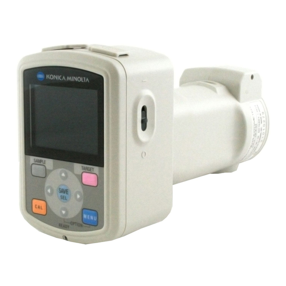
Page 16: Names And Functions Of Parts
Names and Functions of Parts 1 LCD screen Displays setting items, measurement results and messages. 2 Control panel Used to switch screens or select/determine/save setting items. For details, refer to page E-23 “Control Buttons”. 3 AC adapter terminal When using the supplied AC adapter (CM-A305), connect the adapter’s plug to this terminal. 4 USB connection terminal Used to connect the instrument to a PC with the supplied USB cable (IF-A17). - Page 17 Names and Functions of Parts 8 Measurement area selector Used to change the lens position according to the measurement area. The CM-600d does not have this switch. 9 Battery chamber cover The cover of the battery chamber. Four AA-size batteries must be set in the battery chamber with the correct polarity alignment.
-
Page 18: Preparation
• When the White Calibration Cap is not in use, invert it so that the White Calibration Plate is not exposed to ambient light or dust. • When the CM-700d/600d is not in use, you must attach the White Calibration Cap to the instrument to prevent the entry of dust into the integrating sphere through the specimen measuring port. -
Page 19: Attaching/Removing A Target Mask
Preparation Attaching/Removing a Target Mask The CM-700d/600d must be used with a Target Mask conforming to the selected lens position and measurement condition. To attach/remove a Target Mask, follow the procedure given below. • When attaching/removing a Target Mask, be careful not to allow dirt or dust to enter the integrating sphere though the specimen measuring port. -
Page 20: Cleaning Parts
Do not touch the inner surface of the Target Masks with your fingers or wipe them with a cloth to remove dust. If the inside is so dirty that dirt cannot be removed with a blower, contact the nearest KONICA MINOLTA SENSING-authorized service facility. -
Page 21: Attaching Wrist Strap To The Instrument
Preparation Attaching Wrist Strap to the Instrument When measuring by hand, attach Wrist Strap and put your arm through Wrist Strap to prevent dropping of the instrument. [Procedure] Pass one end of Wrist Strap through the strap holder of the instrument. Pass other end of Wrist Strap through the ring, Ring and pass the strap that passed through the strap... -
Page 22: Inserting The Batteries
• Do not use manganese batteries. • if you are not going to use the CM-700d/600d for more than two weeks, the batteries must be removed. If the batteries are left in the instrument for a long time, battery electrolyte may leak and damage the instrument. -
Page 23: Connecting The Ac Adapter
Preparation Connecting the AC Adapter When the external output terminal is used for data communication or printing, more power will be required. In this case, it is recommended to use the AC adapter (AC-A305) rather than batteries. • To supply AC power to the instrument, always use the AC adapter (AC-A305) supplied with the instrument. •... -
Page 24: Turning Power On/Off
The power will be turned OFF. Power Save Function The CM-700d/600d features a power save function which activates the power save mode when none of the measuring and control buttons is operated for a specified period of time. In the power save mode, the screen display is turned off and the flash circuit will not be charged. -
Page 25: System Diagram
Hard Case available) CM-A176 * For storage USB Cable (2 m) IF-A17 Color Data Software CM-S100w AC Adapter AC-A305 CM-700d/600d Wrist Strap CR-A73 CM-700d CM-600d Target Mask φ 8 mm (with glass) Zero Calibration Box φ 8 mm φ 3 mm... -
Page 26: Items You Must Know
The display language can be selected from seven languages including Japanese. For details, refer to page E-66 “Other Settings”. Control Panel The top of the CM-700d/600d contains the LCD screen on which the instrument displays measurement results and messages, and the control... -
Page 27: Status Icons
Description (Status) Meaning Measurement area (Measurement MAV/SAV area selector setting) * The CM-700d shows either the MAV or SAV icon. The CM-600d shows only the MAV icon. Specular component mode setting SCI/SCE/I + E (SCI + SCE) Bluetooth capability setting... -
Page 28: Battery Alarm
“[TARGET] (Back) button”. Battery Alarm The CM-700d/600d can be powered from the standard AC adapter (AC-A305) or AA-size alkaline or nickel-metal-hydride rechargeable batteries. When the instrument is used with batteries, two types of battery alarm indication will appear when battery power level is low. When the battery power is sufficient, no battery alarm indication is displayed. -
Page 29: Chapter 2 Preparation For Measurement
Chapter 2 Preparation for Measurement E-25... -
Page 30: Flow Of Measurement
Flow of Measurement ■ Optional settings ■ Basic procedure Turning Power ON/OFF (page E-20) Setting the Display Language (page E-66) * Perform this step if necessary such as after initialization. Registering Conditions (Cond) (page E-56) * Perform this step if Attaching/Removing a Target Mask (page E-15) necessary according to the measurement conditions. - Page 31 Calibration Zero Calibration Since the CM-700d/600d stores the data of the zero calibration performed at the factory, it is unnecessary to repeat the zero calibration every time you turn ON the instrument. However, if the measurement φ conditions change greatly, or if you use the optional dust cover set or Target Mask 8 mm (with glass), you need to perform zero calibration before white calibration.
- Page 32 Calibration Use the button of the cross key to move the cursor to “Zero Cal.” Direct the specimen measuring port to midair. • Do not direct the specimen measuring port toward a light source (including illumination such as a fluorescent lamp). •...
-
Page 33: White Calibration
Calibration White Calibration White calibration must be performed prior to start of measurement after the power is turned ON for the first time after purchase at the current settings. When white calibration finishes, <white calibration completed icon> is displayed. Once white calibration is completed, measurement is possible without white calibration when the instrument is turned ON the next time. - Page 34 Calibration Properly attach the White Calibration Cap, which has the same pairing number as the instrument. Make sure that (Ready to measure) is displayed or Ready lamp is green, and then press the measuring button. White calibration will be performed. The Xe lamp flashes five times for each SCI and SCE measurement.
-
Page 35: User Calibration
Calibration User Calibration You can perform calibration by using your own reference plate and calibration data instead of the white calibration data. The calibration data for user calibration can be specified by connecting the instrument to a PC and using the optional Color Data software “SpectraMagic™ NX”. You can select whether to use the user calibration data for measurement on the <User Cal.>... -
Page 36: Condition Setting
Condition Setting The CM-700d/600d requires condition settings (display and measurement conditions) before measurement can be started. To configure condition settings, select “Disp. Cond.” (display conditions) or “Meas. Cond.” (measurement conditions) from the <Option> screen to open an appropriate screen. If any predefined condition is selected, the condition setting (display/measurement conditions) is disabled. Set the condition to OFF before starting condition setting. - Page 37 Condition Setting • The <Disp. Cond.> screen shows the current settings. After you set the display conditions, press the [TARGET] (Back) button to return to the <Option> screen. E-33...
- Page 38 ❍Pseudo Color: Display a pseudocolor. ❍Assessment: Display deviations in hue or other factors from the target color with specific words. With the CM-700d/600d, the words are in English. The table below shows the words to be used. ∆a*/∆b*/Hue (h, a*, b*)
- Page 39 Condition Setting Graph Diff. will be displayed only when the target color has The results for “Difference”, “Abs. & Diff.” “ ” been specified. Press the [SAVE/SEL] button. The selection is confirmed and the screen returns to the <Disp. Cond.> screen. If you press the [TARGET] (Back) button without pressing the [SAVE/SEL] button, you return to the <Disp.
- Page 40 Condition Setting Color Space Select the color space to be used. [Setting Procedure] Start the procedure from the <Disp. Cond.> screen. Use the button of the cross key to move the cursor to “Color Space” and then press the [SAVE/SEL] button. The <Color Space>...
- Page 41 Condition Setting Equation Select the color difference formula to be used. [Setting Procedure] Start the procedure from the <Disp. Cond.> screen. Use the button of the cross key to move the cursor to “Equation” and then press the [SAVE/SEL] button. The <Equation>...
- Page 42 Condition Setting Color Index Select the index (WI, YI, etc.) to be used. [Setting Procedure] Start the procedure from the <Disp. Cond.> screen. Use the button of the cross key to move the cursor to “Color Index” and then press the [SAVE/SEL] button. The <Color Index>...
- Page 43 Condition Setting Observer Select the observer angle: 2 or 10 ° ° [Setting Procedure] Start the procedure from the <Disp. Cond.> screen. Use the button of the cross key to move the cursor to “Observer” and then press the [SAVE/SEL] button. The <Observer>...
- Page 44 Condition Setting Illuminant 1 Select the illuminant used to measure colorimetric data. [Setting Procedure] Start the procedure from the <Disp. Cond.> screen. Use the button of the cross key to move the cursor to “Illuminant 1” and then press the [SAVE/SEL] button. The <Illuminant 1>...
- Page 45 Condition Setting Illuminant 2 Select the secondary illuminant used for MI (metamerism index) calculation, etc. [Setting Procedure] Start the procedure from the <Disp. Cond.> screen. Use the button of the cross key to move the cursor to “Illuminant 2” and then press the [SAVE/SEL] button.
-
Page 46: Setting The Measurement Conditions
Condition Setting Setting the Measurement Conditions To set measurement conditions, select “Meas. Cond.” from the <Option> screen. You can select or specify the following four items as the measurement conditions: • Mode: Select the specular component mode. • Wait Time: Specify the delay between the press of the measuring button and the flash of the lamp. •... - Page 47 Condition Setting Mode Select the specular component mode. [Setting Procedure] Start the procedure from the <Meas. Cond.> screen. Use the button of the cross key to move the cursor to “Mode” and then press the [SAVE/SEL] button. The <Mode> screen is displayed. Use the button of the cross key to move the cursor to the desired item.
- Page 48 Condition Setting Wait Time Specify the delay between the press of the measuring button and the flash of the lamp [Setting Procedure] Start the procedure from the <Meas. Cond.> screen. Use the button of the cross key to move the cursor to “Wait Time” and then press the [SAVE/SEL] button.
- Page 49 Condition Setting Auto Averaging (Auto Ave.) Specify the number of measurements for auto averaging. [Setting Procedure] Start the procedure from the <Meas. Cond.> screen. Use the button of the cross key to move the cursor to “Auto Ave.” and then press the [SAVE/SEL] button.
- Page 50 Condition Setting Manual Averaging (Manual Ave.) Specify the number of measurements for manual averaging. [Setting Procedure] Start the procedure from the <Meas. Cond.> screen. Use the button of the cross key to move the cursor to “Manual Ave.” and then press the [SAVE/SEL] button.
-
Page 51: Color Difference Target Color Data Operation
To measure the color difference between two specimens, the color of one of the specimens must be set as the target color. The CM-700d/600d can store up to 1,000 target colors. When using the instrument alone, measure a target specimen by following the procedure below and set the result as the target color. -
Page 52: Target Color Menu
Color Difference Target Color Data Operation Place the specimen measuring port on the specimen. Make sure that (Ready to measure) is displayed or Ready lamp is green, and then press the measuring button. The specimen is measured and the result is displayed on the Target name, screen. - Page 53 Color Difference Target Color Data Operation [Setting Procedure] From the <Target> screen, press the [MENU] button. The <Menu> screen is displayed. Use the button of the cross key to move the cursor to the item to select or execute, and then press the [SAVE/SEL] button.
- Page 54 Color Difference Target Color Data Operation Delete Delete the target color data. When the data is protected, you cannot select “Delete” on the <Menu> screen. [Setting Procedure] Start the procedure from the <Menu> screen of the <Target> screen. Use the button of the cross key to move the cursor to “Delete”...
- Page 55 Color Difference Target Color Data Operation Use the button of the cross key to move the cursor to the desired item. • If is displayed at the top of the screen, you can use the button of the cross key to change the combination of the specular component mode and illuminant used for the screen display.
- Page 56 Color Difference Target Color Data Operation Edit Name Name the target color data. [Setting Procedure] Start the procedure from the <Menu> screen of the <Target> screen. Use the button of the cross key to move the cursor to “Edit Name” and then press the [SAVE/SEL] button.
- Page 57 Color Difference Target Color Data Operation Setting the List (List) Specify the column displayed for each target color No. in the list. [Setting Procedure] Start the procedure from the <Menu> screen of the <Target> screen. Use the button of the cross key to move the cursor to “List”...
- Page 58 Color Difference Target Color Data Operation Data Protection You can specify data protection so that the saved target color setting will not be deleted by accident. When the data protection is specified, “Delete” and “DeleteAll” in the <Menu> screen cannot be selected.
- Page 59 Color Difference Target Color Data Operation Delete All Delete all the target color data which have been set. When the data is protected, you cannot select “DeleteAll” on the <Menu> screen. [Setting Procedure] Start the procedure from the <Menu> screen of the <Target> screen. Use the button of the cross key to move the cursor to “DeleteAll”...
-
Page 60: Registering Conditions (Cond
Registering Conditions (Cond) The CM-700d/600d allows registration of up to 8 conditions (display and measurement conditions) in advance. You can display measurement results under desired conditions by switching registered conditions stored as “Cond 01 to 08”. When “Cond” is ON (When one of Cond 01 to 08 is selected), you cannot set the display and measurement conditions with the <Option>... - Page 61 Registering Conditions (Cond) Use the button of the cross key to move the cursor to the desired registration number (01 to 08), and then press the [SAMPLE] (Edit) button. A screen used to select the display conditions for the selected registration number is displayed.
-
Page 62: Naming A Condition
Registering Conditions (Cond) Naming a Condition You can name a condition for easier management. [Setting Procedure] From the <Cond> screen, press the [MENU] button. The <Menu> screen is displayed. Make sure that “Edit Name” is selected, and then press the [SAVE/SEL] button. The <Edit Name>... -
Page 63: Setting The Default Color Difference Tolerance (Tolerance (Def.))
Setting the Default Color Difference Tolerance (Tolerance (Def.)) With the CM-700d/600d, you can preset and save tolerances which do not depend on the target color data as default values. During measurement, just selecting the tolerance No. allows automatic judgment using the target colors and tolerances. - Page 64 Setting the Default Color Difference Tolerance (Tolerance (Def.)) Use the button of the cross key to move the cursor to the desired registration number (01 to 08). Press the [SAMPLE] (Edit) button. A screen used to set tolerances for the selected registration number is displayed.
- Page 65 Setting the Default Color Difference Tolerance (Tolerance (Def.)) Press the [SAMPLE] (Edit) button and change the setting. • When you select an item which is currently checked and press the [SAMPLE] (Edit) button, the check mark is cleared. When you press the [SAMPLE] (Edit) button again, the cursor moves to the setting value.
-
Page 66: Selecting Color Difference Tolerances
Setting the Default Color Difference Tolerance (Tolerance (Def.)) Selecting Color Difference Tolerances You can set color difference tolerances to individual target colors when they are measured. You can also select one of the predefined tolerances (default tolerances) and use it for judgment. A default tolerance setting can be registered with each registration number from 01 to 08. -
Page 67: Deleting The Default Color Difference Tolerance Setting
Setting the Default Color Difference Tolerance (Tolerance (Def.)) Deleting the Default Color Difference Tolerance Setting Delete the setting of the default tolerance of the selected registration number. [Setting Procedure] Start the procedure from the <Tolerance(Def.)> screen. Use the button of the cross key to move the cursor to the registration number for which you want to delete the setting, and then press the [SAMPLE] (Edit) button. -
Page 68: Naming The Color Difference Tolerance Setting
Setting the Default Color Difference Tolerance (Tolerance (Def.)) Naming the Color Difference Tolerance Setting [Setting Procedure] Start the procedure from the <Tolerance(Def.)> screen. Use the button of the cross key to move the cursor to the registration number for which you want to edit the name, and then press the [SAMPLE] (Edit) button. - Page 69 Setting the Default Color Difference Tolerance (Tolerance (Def.)) Use the button of the cross key to move the cursor, and use the button to change the letter. • Use the button of the cross key to move the cursor backward to correct letters. •...
-
Page 70: Other Settings
Other Settings Other Settings Setting the Display Language The display language can be changed from the factory-set language. Available languages are: English, Japanese, German, French, Spanish, Italian, and Chinese. The language is factory-set to “English”. When the backup battery of the instrument has gone dead or the instrument is initialized (refer to page E-72), the display language is reset to English regardless of the set language. -
Page 71: Setting The Date And Time
Setting the Date and Time The CM-700d/600d has a built-in clock to record the date and time of measurement. Since the date and time have been set at the factory, you do not need to change them under normal conditions. If necessary, you can change the date and time settings. - Page 72 Other Settings If you want to change the date format, move the cursor to “Format” and then press the [SAVE/SEL] button. The <Format> screen is displayed. This step is unnecessary if you do not change the date format. Go to step 6 on the next page. Use the button of the cross key to move the cursor to the desired format and...
- Page 73 Other Settings Press the [SAMPLE] (Edit) button. The cursor moves to the position where the setting can be changed. • Use the button of the cross key to change the values. Every time you change the value of a block, you need to press the [SAVE/SEL] (OK) button to confirm the change.
-
Page 74: Setting The Power Save Mode
Setting the Power Save Mode The CM-700d/600d features a power save function which turns off the screen display and stops the power supply to the flash circuit after no operation was made for a specified period of time. The period before the activation of the power save function can be set to 0 (OFF) or within the range from 1 to 60 minutes. - Page 75 Other Settings Use the button of the cross key to change the time before the power save mode is activated by specifying the number of minutes. Holding down the button of the cross key changes the value continuously. • When you finish changing the setting, press the [TARGET] (Back) button to return to the <Settings>...
-
Page 76: Initialization
Other Settings Initialization Reset the settings of the instrument to the initial status. • Do not initialize the instrument unless necessary. • The measured data, target color data, tolerances set to each target color and default tolerance settings will be protected and not be deleted by initialization. -
Page 77: Measurement
Chapter 3 Measurement E-73... - Page 78 Measurement • Prior to start of measurement, be sure to perform white calibration. For details, refer to page E-29 “White Calibration”. • To display color difference, it is necessary to set target colors before measurement. • For accurate measurement, make sure to keep measurement conditions (ambient temperature etc.) constant. [Setting Procedure] Press the [SAMPLE] button.
-
Page 79: Displaying The Measurement Results
Displaying the Measurement Results At the end of measurement, the measurement results will be displayed on the LCD according to the specified measurement conditions. Typical measurement result screens are shown below. You can switch the measurement result screens with the button of the cross key. -
Page 80: Pass/Fail Judgment
Displaying the Measurement Results Pass/Fail Judgment The following screens are displayed when “Judge” has been selected for “Disp. Type” of the current display conditions. • When the result was “Pass” The background is shown in green. • When the result was “Fail” The background is shown in red. -
Page 81: Spectral Reflectance Graph
Displaying the Measurement Results • Color difference graph L* axis (color difference graph) a * axis (color difference graph) b * axis (color difference graph) Measuring point Scales for the axes Specified box tolerances Position of target color Spectral Reflectance Graph The following screen is displayed when “Graph Spec.”... -
Page 82: Switching The Display Contents Of The Measurement Results
Displaying the Measurement Results Switching the Display Contents of the Measurement Results The contents of the measurement result display can be changed by pressing of the cross button key on the <Sample> screen. The contents will vary depending on the display type setting. The color difference is displayed only when target data has been set. - Page 83 Displaying the Measurement Results Table legend : The screen is displayed. ❍ : The screen is displayed, but the result “---” will be displayed; or the measurement result will not be displayed. : The screen is displayed, but the item will not be displayed. Shadowed : The screen is not displayed.
- Page 84 Displaying the Measurement Results Display order of the measurement result screens (when all the items are selected for “Disp. Type”.) 1 Absolute value/SCI/ 11 Color difference & Illuminant 1 Absolute value/SCE/ Illuminants 1 and 2 12 Color index/SCE/ 2 Absolute value/SCI/ Illuminants 1 and 2 Illuminant 2 13 Judgment...
-
Page 85: Measured Data Operation
Measured Data Operation The following operations are available for the measured data. • Print: Print the measured data. • Delete: Delete the measured data. • Edit Name: Name the measured data. • List: Specify the columns displayed for each sample data No. in the list. •... -
Page 86: Print
Measured Data Operation Print Print the measured data. You need to establish a connection between the instrument and a Bluetooth printer in advance. If proper connection is not established, you cannot select “Print” on the <Menu> screen. [Operating Procedure] Start the procedure from the <Menu> screen of the <Sample> screen. Use the button of the cross key to move the cursor to “Print”. -
Page 87: Edit Name
Measured Data Operation Use the button of the cross key to move the cursor to “OK” and press the [SAVE/SEL] button. Data will be deleted. When data is deleted, the subsequent sample data Nos. will be reassigned, reducing them by one. •... -
Page 88: Setting The List (List
Measured Data Operation Setting the List (List) When the <Sample> screen is displayed, pressing the [SAVE/SEL] button switches the screen between the list display and detail display. Specify the columns displayed for each sample data No. in the list. [Setting Procedure] Start the procedure from the <Menu>... -
Page 89: Deleteall
Measured Data Operation [Setting Procedure] Start the procedure from the <Menu> screen of the <Sample> screen. Use the button of the cross key to move the cursor to “Auto Target” and then press the [SAVE/SEL] button. The <Auto Target> screen is displayed. Use the button of the cross key to move the cursor to “ON”... - Page 90 Measured Data Operation Use the button of the cross key to move the cursor to “OK” and press the [SAVE/SEL] button, and the data is deleted. • When the deletion is complete, the screen returns to the <Menu> screen. • When you place the cursor on “Cancel” and press the [SAVE/SEL] button, the deletion is canceled and the screen returns to the <Menu>...
-
Page 91: Chapter 4 Other Functions
Chapter 4 Other Functions E-87... -
Page 92: Average Measurement
When taking measurements or setting target colors, more accurate data can be obtained if the averaging function is used. With the CM-700d/600d, the following two averaging functions are available. • Manual Averaging : When the color of the specimen is not uniform, measurements are performed at different positions on the specimen and then the average of the measured spectral reflectance data is calculated. - Page 93 Average Measurement Make sure that (Ready to measure) is displayed or Ready lamp is green, and then press the measuring button. The number of completed measurements and the measured value will be displayed during measurement. To cancel the measurement, press the [TARGET] (Cancel) button.
-
Page 94: Auto Averaging
Average Measurement Auto Averaging Measurement is repeated the specified number of times at the same position on the specimen and then the average of the measured spectral reflectance data is calculated. This will improve the accuracy of the measured data. The measurement procedure is as shown below. -
Page 95: Pass/Fail Judgment For Color Difference
You can set tolerances for the color difference of the measured data from the target color data to make pass/fail judgment. The CM-700d/600d uses box tolerances for judgment. The tolerances can also be set for “Cond 01 to 08” on the <Option> screen. For details, refer to page E-50 “Tolerance (Box Tolerance) Setting”. - Page 96 Pass/Fail Judgment for Color Difference Press the [MENU] button. The <Menu> screen is displayed. Use the button of the cross key to move the cursor to “Tolerance” and then press the [SAVE/SEL] button. The <Tolerance> screen is displayed. • To display the other tolerance setting items, press the button of the cross key.
- Page 97 Pass/Fail Judgment for Color Difference Place the specimen measuring port on the specimen, and press the measuring button. The specimen is measured and the judgment results are displayed according to the display type specified for the display conditions. • When the display type is “Absolute” or “Abs. & Diff.” The values which failed the judgment are highlighted in red.
-
Page 98: Connecting To An External Device
Connect the instrument to a PC with the supplied USB cable IF-A17 (2 m). • To connect the instrument to a PC, you need to install the USB driver for the CM-700d/600d. Install the USB driver supplied with the software that enables connection and operation of the instrument. - Page 99 Connecting to an External Device [Operating Procedure] In general, a USB cable can be connected/disconnected while the instrument is turned ON, however, you need to turn OFF the instrument in the procedure below. Turn OFF the instrument (Slide the Power switch to “...
- Page 100 Connecting to an External Device To use the Bluetooth capability of the instrument to connect a PC, you need to prepare both the instrument and the PC to establish Bluetooth communication. For details, refer to the instruction manual of the Bluetooth adapter. Preparation of the Instrument Set the Bluetooth capability of the instrument to ON.
- Page 101 Connecting to an External Device Preparation of the PC Attach the Bluetooth adapter to the PC to enable Bluetooth communication. The following describes a basic procedure. For details, refer to the instruction manual of the Bluetooth adapter. [Operating Procedure] Install the utility software supplied with the Bluetooth adapter on the PC. Attach the Bluetooth adapter to the USB port of the PC, and ensure that the PC properly recognize the adapter.
-
Page 102: Connecting A Printer
Connecting to an External Device From the PC, search for Bluetooth devices and select “KMSEA_xxxxxxxx (where xxxxxxxx is the serial number of the instrument)” from the listed devices. Execute the “Bluetooth to serial connection”. When the connection is established, the LCD display of the instrument shows “Communicating”. - Page 103 Connecting to an External Device Preparation of the Instrument Set the Bluetooth capability of the instrument to ON. You cannot register a Bluetooth printer or set Auto Print until the Bluetooth capability of the instrument is set to [Operating Procedure] Hold down the [MENU] button and press the button of the cross key.
- Page 104 Connecting to an External Device Establishing the Connection between the Instrument and Printer Set the instrument as a host and establish a connection between the instrument and Bluetooth printer via Bluetooth communication. Confirm the following before starting the procedure below. •...
- Page 105 Connecting to an External Device Confirm that “Search” is highlighted and then press the [SAVE/SEL] button. Available Bluetooth devices are searched for and the result is listed on the LCD screen. • From the list, find the Bluetooth address of the printer you checked during the procedure of page E-98 “Preparation of the Printer”.
- Page 106 Connecting to an External Device Printing Measured Data Print the measured data with the printer. • You need to establish the connection between the instrument and printer in advance. • The Bluetooth printer can print text data only. Note that you cannot print graphs even when you selected spectral graph or color difference graph for the display type for the instrument.
- Page 107 Connecting to an External Device Auto Print Print measurement results automatically from the printer every time measurement is performed. • You need to establish the connection between the instrument and printer in advance. • The Bluetooth printer can print text data only. Note that you cannot print graphs even when you selected spectral graph or color difference graph for the display type for the instrument.
- Page 108 Connecting to an External Device • Print Example 1 Display type is Graph Spec (spectral graph). • Print Example 2 Display type is Graph Diff. (color difference graph). E-104...
- Page 109 Connecting to an External Device • Print Example 3 Display type is Judge. • Print Example 4 Display type is Abs. & Diff. (absolute value & color difference)/Assessment (color assessment). • Print Example 5 Display Type is Pseudo Color. E-105...
-
Page 110: Displaying The Instrument Information
Displaying the Instrument Information Display the model name, version, and serial number of the instrument. [Operating Procedure] Hold down the [MENU] button and press the button of the cross key. The <Option> screen is displayed. Use the button of the cross key to move the cursor to “Instrument”... -
Page 111: Chapter 5 Troubleshooting
Chapter 5 Troubleshooting E-107... -
Page 112: Error Messages
If the trouble does not go away in spite of taking action, contact a KONICA MINOLTA SENSING-authorized service facility. Messages that may be displayed on the LCD are given in the table below. For communication error check codes, refer to the separate document. - Page 113 If this message is still IN CHARGING • Battery exhausted displayed after battery replacement, contact a KONICA MINOLTA • Breakdown of charging circuit SENSING-authorized service facility. ER030 Data has been lost since the memory’s...
-
Page 114: Troubleshooting
If an abnormality has occurred with the instrument, take necessary actions as given in the table below. If the instrument still does not work properly, turn the power OFF, and then turn it ON again. If the symptom remains, contact a KONICA MINOLTA SENSING-authorized service facility. Symptom... -
Page 115: Chapter 6 Appendix
Chapter 6 Appendix E-111... -
Page 116: Principles Of Measurement
Principles of Measurement Illuminating/Viewing System This instrument utilizes the di:8°/de:8° geometry conforming to CIE No. 15, ASTM E1164, DIN 5033 Teil 7, ISO 7724/1, and JIS Z8722-1982 (diffused illumination, 8-degree viewing angle) standards, and offers measurement with automatic SCI (specular component included) and SCE (specular component excluded) switching. -
Page 117: Illumination Area And Measurement Area
Communication Mode The CM-700d/600d is set to the communication mode when it is connected to a PC. When the instrument is controlled from the PC, the instrument's LCD screen shows “Communicating”. While this message is displayed, the buttons of the instrument are disabled. -
Page 118: Initial Settings
Principles of Measurement Initial Settings * Initialization of the instrument will reset the settings to the initial values shown in the table below. The measured data, target color data and tolerances set for each target color are protected and not cleared by the initialization. -
Page 119: Specifications
Specifications Model CM-700d CM-600d di:8°, de:8° (diffused illumination, 8-degree viewing angle), SCI (specular component included)/SCE (specular component Geometry excluded) selectable (with automatic-switching function) (Conforms to CIE No. 15, ISO7724/1, DIN5033 Teil7, ASTM E 1164, JIS Z 8722) Light source Pulsed xenon lamp (with UV cut filter) φ... - Page 120 ® ® Bluetooth is a registered trademark of Bluetooth SIG, Inc. and it is used under license agreement. The CM-700d/600d incorporates the eT-Kernel/Standard and PrUSB/Device from eSOL Co., Ltd. Model CM-700d CM-600d Standard White Calibration Cap (w/ white calibration data CD-R): CM-A145 accessories φ...
-
Page 121: Dimensions
Dimensions (mm) φ24 φ50.6 Tripod mounting screw hole, Depth: 5.5 φ60 E-117... - Page 122 Dimensions E-118...
- Page 124 © 2007 KONICA MINOLTA SENSING, INC. 9222-A0E8-11 AHMAGA...
Need help?
Do you have a question about the CM-700d and is the answer not in the manual?
Questions and answers