Table of Contents
Advertisement
Quick Links
Advertisement
Table of Contents
Troubleshooting

Related Manuals for Konica Minolta CM-2600d


Summary of Contents for Konica Minolta CM-2600d
- Page 1 Spectrophotometer CM-2600d/2500d Instruction Manual Manual de instrucciones...
-
Page 2: Safety Symbols
Disconnect the AC power cord from the AC outlet. Notes on this Manual • Copying or reproduction of all or any part of the contents of this manual without KONICA MINOLTA SENSING’s permission is strictly prohibited. • The contents of this manual are subject to change without prior notice. -
Page 3: Safety Precautions
OFF immediately, disconnect the AC adapter from the AC outlet (or remove the batteries if they are used), and con- tact the nearest KONICA MINOLTA SENSING-authorized service facility. (Falling to adhere to the following points may result in CAUTION injury or damage to the instrument or other property.) -
Page 4: Notes On Use
• This instrument and the AC adapter supplied as a standard accessory have been designed exclusively for indoor use. • Do not leave the CM-2600d/2500d in direct sunlight or near sources of heat, such as stoves etc. The internal temperature of the instrument may become much higher than the ambient temperature in such cases. -
Page 5: Notes On Storage
• If you are not going to use the CM-2600d/2500d for more than two weeks, the batteries must be re- moved. If the batteries are left in the instrument, leakage may occur resulting in damage to the instru-... -
Page 6: Notes On Cleaning
Notes on Cleaning • If the CM-2600d/2500d becomes dirty, wipe it with a soft, clean dry cloth. Never use solvents such as thinner and benzene. • If the White Calibration Plate becomes dirty, wipe it gently with a soft, clean dry cloth. If dirt is diffi- cult to remove, contact the nearest service facility listed on the attached sheet. -
Page 7: Table Of Contents
Contents Safety Precautions .......................... Notes on Use..........................Notes on Storage......................... Notes on Cleaning........................Conventions ..........................Chapter 1 Before Using the Instrument Accessories............................E-10 Standard Accessories ........................E-10 Optional Accessories ........................E-11 Names and Functions of Parts....................... E-12 Preparation ............................. E-14 Attaching/Removing a Target Mask................... - Page 8 Contents Setting the Number of Measurements for Auto Averaging............E-40 Setting the Delay Time ....................... E-41 Zero Calibration ..........................E-44 White Calibration........................... E-46 Setting a Color Difference Target Data..................E-48 Selecting a Color Difference Target Data ..................E-50 Deleting a Color Difference Target Data..................E-51 Setting Color Difference Tolerances .....................
- Page 9 Contents UV Control ..........................E-118 Target Mode............................ E-119 Relation Between Measured Data and Target Color ..............E-119 Deleting a Color Difference Target Data..................E-119 Notes on Changing the Target Mode..................E-119 Specifications........................... E-123 Dimensions ............................E-125 Menu Structure..........................E-126 Reading the menu structure diagram ..................E-126 Menu Structure diagram ......................
-
Page 10: Conventions
• Organization The CM-2600d/2500d (Ver. 1.30 or higher) supports two types of the target mode, “linked to each data.” and “defined in COND.”; the procedure and details for these types varies slightly. This manual describes the procedures for the default target mode, which is “linked to each data.”. It only includes information for the “defined in COND.”... -
Page 11: Chapter 1 Before Using The Instrument
Chapter 1 Before Using the Instrument... -
Page 12: Accessories
• This accessory can be used as a table on which to store the CM-2600d/ 2500d. • In the case of the CM-2600d, a Target Mask that is not in use can be stored on this accessory. Target Mask CM-A146 (for ø8 mm) CM-A147 (for ø3 mm) -
Page 13: Optional Accessories
Zero Calibration Box (CM-A32) Used to perform zero calibration. Hard Case (CM-A148) Can be used for storing the CM-2600d/2500d, the instruction manual and standard accessories, such as the White Calibration Plate and AC adapter. The Hard Case is designed purely for storing the above items and must not be used for transportation purposes. -
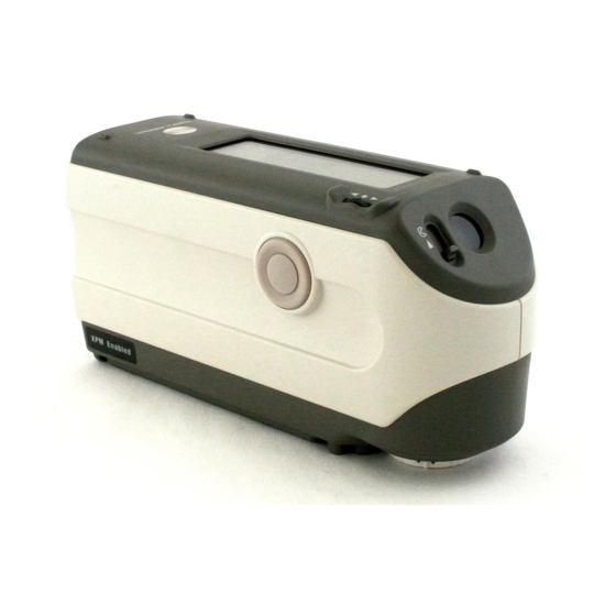
Page 14: Names And Functions Of Parts
4 LCD display Displays the setting items and measured data. 5 Specimen measuring port A port provided to measure the specimen. With the CM-2600d, a Target Mask must be attached to this port, according to the measurement area selector position. E-12... - Page 15 2 White Calibration Plate Used to perform white calibration of the CM-2600d/2500d. If you are not going to use it, attach the cap to prevent exposure to ambient light and protect it from scratches and dust.
-
Page 16: Preparation
Attaching/Removing a Target Mask With the CM-2600d, a Target Mask conforming to the selected lens position and measurement condition must be used. A Target Mask that is not in use can be attached to the Target Mask mount section of the White Calibration Plate, so that it can be stored together with the instrument. - Page 17 Storing a Target Mask In the case of the CM-2600d, a Target Mask that is not in use can be attached to the Target Mask mount section of the White Calibration Plate, so that it can be stored together with the instrument.
-
Page 18: Attaching/Removing The "Measuring Base
The “Measuring Base” is shown in the illustration to the right, Measuring Base and is attached to the base of the CM-2600d/2500d with two screws. • Make sure that the “Measuring Base” is securely attached to the instrument before calibrating the instrument or taking measure- “Measuring Base”... -
Page 19: Cleaning Each Part
Do not touch the inner surface of the Target Masks with your fingers or wipe them with a cloth. If the Target Masks are so dirty that dirt cannot be removed with a blower, contact the nearest KONICA MINOLTA SENSING- authorized service facility. -
Page 20: Inserting The Batteries
Preparation Inserting the Batteries To supply power to the instrument, the AC adapter (AC-A17) or four AA-size batteries (Alkaline or Ni- MH battery is recommended for better service life) must be used. Use either the AC adapter or batteries, according to which suits your application. •... -
Page 21: Connecting The Ac Adapter
Preparation Connecting the AC Adapter Use of the AC adapter (AC-A17) rather than batteries is recommended, since more power will be required when the external output terminal is used to output data to an external device or print it. • To supply AC power to the instrument, always use the AC adapter (AC-A17) supplied with the instrument.(Rat- ed: 5 V, 2.8 A) •... -
Page 22: Turning Power On
Preparation Turning Power ON When turning the power ON for the first time, the display language and measurement mode must be set. For details, refer to page E-27. [Operating Procedure] Set the POWER switch to “|”. The power will be turned ON. Turning Power OFF [Operating Procedure] Set the POWER switch to “... -
Page 23: System Configuration
Optional accessories CM-A147 * Not supplied with the CM-2500d. Target Mask 8 mm CM-A146 AA-size battery AC Adapter ( 4) AC-A17 CM-2600d (CM-2500d) * with Measuring Personal computer Base RS-232C Cable (commercially available) IF-A16 White Calibration Plate CM-A145 Printer Cable... -
Page 24: Items You Must Know
Items You Must Know Language Mode Contents on the LCD screen can be displayed in English, Japanese, German, French, Spanish or Italian. In this manual, explanation of operating methods and display is given for English mode. Measurement Mode Two measurement modes (COND and TASK) are available with this instrument, and can be switched from one to another. -
Page 25: Target Modes
Items You Must Know Target Modes • The CM-2600d/2500d supports two Target Modes, “defined in COND.” mode and “linked to each data.” mode, to analyze both measurement data and color difference. As with Language Mode and Measurement Mode, you can select the desired mode when you turn the power ON. -
Page 26: Data Saving
Items You Must Know Data Saving Data used with this instrument is saved automatically. Although white calibration data is retained in in- ternal memory even after power is turned off, it is still necessary to repeat white calibration each time you switch the power back on. -
Page 27: Chapter 2 Preparation For Measurement
Chapter 2 Preparation for Measurement E-25... -
Page 28: Flow Of Measurement
Flow of Measurement For the first time For the second and subsequent times Turning Power On for the First Time Turning Power ON (see page E-20) (see page E-27) Initial Setting (see page E-29) Selecting a Measurement Condition (see page E-33) Setting a Measurement Condition (see page E-34) Zero Calibration (see page E-44) -
Page 29: Turning Power On For The First Time
Turning Power On for the First Time When turning the power ON for the first time, the display language and measurement mode must be set. Setting the Language Mode and Measurement Mode Set the language and measurement mode as follows: [Setting Procedure] While pressing A, turn the power ON. -
Page 30: Selecting The Target Mode
Turning Power On for the First Time TARGET • If a task(s) has been downloaded to the instrument, both “COND” and “TASK” will be displayed. • Select “COND”. Selecting the Target Mode The default setting is linked to each data. mode. -
Page 31: Initial Setting
Initial Setting The following five initial setting items are available. (1) REMOTE..... Connects the instrument to the PC to enable bi-directional communications. (2) AUTO PRINT....If the instrument is connected to a printer, measured data will be printed au- tomatically each time measurement is taken. (3) CLOCK...... -
Page 32: Setting The Date And Time
Initial Setting Setting the Date and Time [Setting Procedure] <MENU> screen Turn B to select “CLOCK”, then press A. Turn B to select “ADJUST”, then press A. The cursor will move to the current- ly set date, allowing you to change Turn B to select the desired date and time, then press A. -
Page 33: Setting The Display Direction
Initial Setting Setting the Display Direction [Setting Procedure] <MENU> screen Turn B to select “DISPLAY INVERT”, then press A. The contents displayed on the LCD will be reversed each time pressed. E-31... -
Page 34: Setting The Lcd Contrast
Initial Setting Setting the LCD Contrast [Setting Procedure] <MENU> screen Turn B to select “LCD CONTRAST”, then press A. Turn B to adjust the LCD contrast, then press A. The contrast you set will be con- firmed, and the <MENU> screen will reappear. -
Page 35: Selecting A Measurement Condition
Selecting a Measurement Condition Before starting measurement, the desired measurement condition (COND1 to COND6) must be selected. • Up to six sets of measurement conditions (COND1 to COND6) can be set. • Measurement conditions must be set before start of measurement. For details, refer to page E-34. [Setting Procedure] <INITIAL>... -
Page 36: Setting A Measurement Condition
[Setting Procedure] <FILE> screen Turn B to select “SEL”, then press A. For CM-2600d “MASK/GLOSS” will be highlight- For CM-2500d • Only those conditions whose measurement area is MAV can be selected. -
Page 37: Setting The Measurement Area And Specular Component Mode
Setting a Measurement Condition Setting the Measurement Area and Specular Component Mode Turn B to select the desired setting, then press A. <Settings> • M/I+E: Measurement area:ø8 mm, simultaneous measurement of SCI (Specular Component Includ- ed) and SCE (Specular Component Excluded) •... -
Page 38: Setting The Uv
Setting a Measurement Condition Setting the UV Turn B to select “UV SETTING”, then press A. For CM-2600d <Settings> • UV100%: Measurement is performed with an illumination that contains all UV components of Xe flash light source. • UV0%: Measurement is performed with an illumination that contains no UV components of Xe flash light source. -
Page 39: Selecting Illuminant 2
Setting a Measurement Condition Selecting Illuminant 2 As explained in “Selecting Illuminant 1”, select the desired illuminant, then press <Settings> • Same as those given in “Selecting Illuminant 1” • To display MI (metamerism index), an illuminant must be selected for ILLUMINANT 2. Selecting the Observer Turn B to select the desired observer angle, then press A. -
Page 40: Selecting The Display Mode
Setting a Measurement Condition Selecting the Display Mode Turn B to select the desired display mode, then press A. <Settings> • DIFF&ABS: Displays the absolute value and the color difference in relation to the target color. (Only absolute value or only color difference can be displayed.) If pass/fail judgment is made according to the specified box color difference tolerances, the failed factor of the measured data will be highlighted. -
Page 41: Selecting A Color Space
Setting a Measurement Condition Selecting a Color Space Turn B to select the desired color space, then press A. Locating the highlighted cursor to by turning B will display the next page of the color space list. Locating the highlighted cursor to by turning B will display the previous page of the color space list. - Page 42 Setting a Measurement Condition • The coefficient for CIE00 (kl:kc:kh) is (1:1:1). This can be changed using SpectraMagic NX (except for Ver. 1.50 or earlier). If the coefficient (kl:kc:kh) is re-specified after measurement, the measurement data will be replaced with data calculated based on the new coefficient. E-40...
-
Page 43: Setting The Number Of Measurements For Manual Averaging
Setting a Measurement Condition Setting the Number of Measurements for Manual Averaging Manual averaging settings can be made as follows: For details, refer to “Manual Averaging” (page E-76). Turn B to select the number of measurements to be performed, then press <Settings>... -
Page 44: Setting The Delay Time
Setting a Measurement Condition Setting the Delay Time Turn B to set the desired delay time, then press A. <Settings> • DELAY TIME: The delay time is used to prevent influences caused by movement of the hands, and is the duration from when the MEAS. - Page 45 Setting a Measurement Condition • “T*” does not appear if “defined in COND.” mode is selected. Selecting “CALIBRATION” by turning B and pressing A will display the <CALIBRATION> screen. So, perform the desired calibration according to step 3 and subsequent steps given in “Zero Calibra- tion”...
- Page 46 • “T*” does not appear if “defined in COND.” mode is selected. Selecting “PREV” by turning B and pressing A again will cause the <INI- TIAL> screen to reappear. So, set another measurement condi- tion according to the procedure giv en in “Selecting a Measurement Condition”...
-
Page 47: Zero Calibration
Zero Calibration Zero Calibration When you use this instrument for the first time or when you have initialized it, zero calibration must be performed. Zero calibration is also sometimes required when measurement conditions are changed. Once zero calibration is completed, the zero calibration data will be kept even if the power is turned OFF. Thus, it is not necessary to perform zero calibration each time the power is turned ON. - Page 48 Turn B to select “ZERO”. Direct the specimen measuring port into the air. 1m or more • Never place the specimen measuring port toward a light source. • Keep the specimen measuring port more than 1m away from any reflective items (hands, desks, walls etc.).
-
Page 49: White Calibration
White Calibration White Calibration White calibration must be performed prior to start of measurement after the power is turned ON. • Own calibration data has been registered to the White Calibration Plate supplied with the instrument. • Although white calibration data is retained in internal memory even after power is turned off, it is still necessary to repeat white calibration each time you switch the power back on. - Page 50 Turn B to select “WHITE”. Note that the White Calibration Plate No. is displayed. Place the instrument on the correct White Calibration Plate (i.e. the calibration plate whose plate No. is displayed in the screen). is displayed, then press C (MEAS. button). Make sure that White calibration will be performed.
-
Page 51: Setting A Color Difference Target Data
Setting a Color Difference Target Data Setting a Color Difference Target Data To measure the color difference between two specimens, the color of one of the specimens must be set as the target color. Up to 1700 target colors can be set for color difference measurement. (700 can be set in the “defined in COND”... - Page 52 Place the specimen measuring port to the specimen. is displayed, then press C (MEAS. button). Make sure that The lamp will flash, measurement will be taken, then the result will ap- pear on the LCD. • The navigation wheel and MEAS. button cannot be used for three seconds after the MEAS. button is pressed, if “UV100%”...
-
Page 53: Selecting A Color Difference Target Data
Selecting a Color Difference Target Data Selecting a Color Difference Target Data To measure the color difference between two specimens, the target color to be used for measurement must be selected from those set in “Setting a Color Difference Target Data”. To select a target color, follow the procedure given below. -
Page 54: Deleting A Color Difference Target Data
To make pass/fail judgment during measurement, it is necessary to set tolerances for the target color to be used. For details, refer to “Setting Color Difference Tolerances” (page E-52). Deleting a Color Difference Target Data There are two methods for deleting target color data. One is to delete the target color data set in “T ”... -
Page 55: Setting Color Difference Tolerances
Setting Color Difference Tolerances Setting Color Difference Tolerances This instrument allows you to set tolerances for the measured color difference, to make pass/fail judgment. Pass/fail judgment is made based on two types of tolerances: box tolerances and elliptical tolerances. Pri- or to start of measurement, tolerances must be set. - Page 56 Setting Color Difference Tolerances Turn B to select the desired target color no. (T ), then press A. “E” will return to “D” • Keeping B held down to left or right will cause the target color No. to change continuously. Turn B to select “TOLERANCE”, then press A.
- Page 57 Setting Color Difference Tolerances Turn B to select the value for an item to be set, then press A. The selected value will be set, and the cursor will move to the next value. Keeping held down will cause the cursor to move from one value to another continuously.
-
Page 58: Elliptical Tolerance
Setting Color Difference Tolerances Elliptical Tolerance Provided to judge whether the measured color difference is within the ellipse set for the target color. • Elliptical tolerances must be set using the “L*a*b*” color space axis if “L*C*h” has been selected as the color space. - Page 59 Setting Color Difference Tolerances Turn B to select “TOLERANCE”, then press A. A screen that allows selection of the tolerance type will appear. If tolerances have already been set, they will be displayed, so skip to step 6. Turn B to select “ELLIPTICAL”, then press A. Turn B to select “ADJUST”, then press A.
- Page 60 Setting Color Difference Tolerances • Keeping B held down to left or right will cause the value to change continuously. • “MAJOR” in the L*a*b* color space will be “a*” axis when “OFFS.” and “ROTAT.” on the “a*b*” plane are “0” (ZERO). •...
- Page 61 Setting Color Difference Tolerances Clearing Tolerances To change the tolerance type, it is necessary to clear the currently set tolerances. To clear the currently set tolerances, follow the procedure given below: [Setting Procedure] <TARGET> screen 1. Turn B to select “TOLERANCE”, then press A. The currently set tolerances will be dis- played.
- Page 62 Setting Color Difference Tolerances E-60...
-
Page 63: Measurement
Chapter 3 Measurement E-61... - Page 64 Measurement To perform measurement, you need to switch from a screen in which “BREAK” is displayed to the meas- urement screen. To perform measurement, follow the procedure given below: • Prior to start of measurement, be sure to perform white calibration. For details, refer to “White Calibration” (page E-46). •...
- Page 65 Measurement • Measurement will no longer be possible once the total number of target color data and measured data reaches 1700 (700 in the “defined in COND.” mode). In this case, delete some target color data or measured data. • The navigation wheel and MEAS. button cannot be used for three seconds after the MEAS. button is pressed, if “UV100%”...
-
Page 66: Displaying The Measurement Results
Displaying the Measurement Results At the end of measurement, the measurement results will be displayed on the LCD according to the spec- ified measurement condition. Typical measurement result screens are shown hereafter. To change LCD’s display contents, change them in the corresponding <COND >... -
Page 67: Pass/Fail Judgment
Displaying the Measurement Results Pass/Fail Judgment The following screen appears if “PASS/FAIL” has been selected for “DISPLAY” mode and tolerances have been set. • When the result is “PASS” 1 Ready to measure. 2 Currently selected <COND > no. 3 Mask/gloss/UV at the time of measurement 4 Currently selected observer/illuminant 5 Currently selected measured data no. -
Page 68: Color Difference Graph
Displaying the Measurement Results Color Difference Graph The following screen appears if “COLOR GRAPH” has been selected for “DISPLAY” mode. The L*a*b* color difference value and the assessment message will be displayed in this screen regardless of the color space selected for “COLOR SPACE” condition item. The data will be plotted in a color differ- ence graph with the selected target color as the origin. -
Page 69: Spectral Reflectance Graph
Displaying the Measurement Results • Color difference graph L* axis (color difference graph) a* axis (color difference graph) b* axis (color difference graph) K Measuring point L Scale for each axis M Specified box tolerances N Position of target color Spectral Reflectance Graph The following screen appears if “SPECT. -
Page 70: Assessments
Displaying the Measurement Results B Deletes the currently displayed measured data. C Displays other measred data. D Outputs the currently displayed measured data to the printer. E Returns to the <COND > screen. F Appears if there is insufficient battery power when the instrument is powered by the battery. - Page 71 Displaying the Measurement Results • Displaying Assessment by Elliptical Tolerance 1 Ready to measure. 2 Currently selected <COND > no. 3 Mask/gloss/UV at the time of measurement 4 Currently selected observer/illuminant 5 Currently selected measured data no. 6 Currently selected target color data no. 7 Color Difference from the target, result of PASS/FAIL judgment and message indicating the deviation direction 8 Measurement date.
-
Page 72: Switching The Display Contents Of The Measurement Results
Displaying the Measurement Results Switching the Display Contents of the Measurement Results In the measurement screen that appears at the end of measurement, the following data will be displayed according to the settings made in the <FILE> screen. The display contents can also be changed. Selecting “DISP”... - Page 73 Displaying the Measurement Results Screen Switching Measurement Screen 1 Measurement Screen 2 Measurement Screen 3 Color difference, absolute value Color difference only Absolute value only Color difference, absolute value Metamerism index (MI)* Color difference only Absolute value only Metamerism index (MI)* Color difference, absolute value Color difference, absolute value Color difference only...
-
Page 74: Deleting Measured Data
Displaying the Measurement Results Deleting Measured Data There are two methods of deleting measured data. One is to delete the data items displayed on the LCD one by one. The other is to delete all the data items for the selected measurement condition (COND1 to COND6). - Page 75 Displaying the Measurement Results Deleting All Data At Once All the data items for the selected measurement condition (COND1 to COND6) can be deleted at once. • Never turn OFF the instrument while global deletion is in progress. • Should the instrument be turned OFF during global deletion, the measured data for all the measurement con- ditions (COND1 to COND6) as well as for all the tasks will be deleted.
-
Page 76: Abbreviations On Lcd Display
Displaying the Measurement Results Abbreviations on LCD Display To facilitate the user’s understanding of various types of information displayed on the instrument’s LCD, the following abbreviations are commonly used. • For notation of values to be set in each setting screen (e.g. measurement conditions), refer to the description given in the corresponding operating procedure. -
Page 77: Measurement Results For "Linked To Each Data
Displaying the Measurement Results Measurement Results for “linked to each data.” This instrument can set multiple target color data numbers and select one of those for displaying the re- sults for the color difference. It can also easily switch the selected target color number using the naviga- tion wheel. - Page 78 Displaying the Measurement Results When the Target Color Data No. has Been Deleted If the target color data for a number is deleted, the target color for data to which that number was asso- ciated is set to that of the next highest number. The target color number is reset to that of the number for which there is a target color data number.
-
Page 79: Chapter 4 Other Functions
Chapter 4 Other Functions E-77... -
Page 80: Measuring The Average
Measuring the Average When taking measurements or setting target colors, more accurate data can be obtained if the averaging function is used. The following two averaging functions are available. • Manual Averaging: When the color of the specimen is not uniform, measurements are performed at different positions on the specimen and then the average of the measured reflect- ance data is calculated. - Page 81 Measuring the Average Place the specimen measuring port to the specimen to be measured, and then press C (MEAS. button). If 2 is set for “MANUAL AVG. TIMES” or if 3 or a higher value is set and the standard deviation is not below the specified one, place the specimen measuring port to the next place and then press...
-
Page 82: Auto Averaging
Measuring the Average Auto Averaging Measurement is repeated the specified number of times in the same position on the specimen and then the average of the measured reflectance data is calculated. This will improve the accuracy of the meas- ured data. Set the number of measurements to be performed and the standard deviation, and then start measurement. -
Page 83: Pass/Fail Judgment For Color Difference
Pass/Fail Judgment for Color Difference This instrument allows you to set tolerances for the measured color difference, to make pass/fail judg- ment. Two kinds of pass/fail judgment methods are available. One is based on the specified box tolerances, and the other is based on the specified elliptical tolerances. In “linked to each data.”... - Page 84 Pass/Fail Judgment for Color Difference Turn B to select “TOLERANCE”, then press A. The currently set tolerances will be displayed. If they are satisfactory, turn B to select “BREAK”, then press A. The measurement screen will ap- pear. Place the specimen measuring port to the specimen, and then press C (MEAS. button). <If “DIFF&ABS”...
-
Page 85: Pass/Fail Judgment Based On Elliptical Tolerances
Pass/Fail Judgment for Color Difference • If “PASS/FAIL” has been selected as the display mode, “PASS” will be displayed only when all the items have passed. • If “DIFF/ABS” has been selected as the display mode, the values for the items which have failed will be high- lighted •... - Page 86 Pass/Fail Judgment for Color Difference Turn B to select “TOLERANCE”, then press A. The currently set tolerances will be displayed. If they are satisfactory, turn B to select “BREAK”, then press A. The measurement screen will ap- pear. Place the specimen measuring port to the specimen, and then press C (MEAS. button).
-
Page 87: Assessments
Assessments This instrument allows assessment of measurement results by simultaneously displaying the direction of tint deviation from the target color, the color difference from the target color and pass/fail judgment based on the specified tolerances. To use this function, make sure that color difference tolerances are set in advance. Assessment by Box Tolerances [Setting Procedure] <COND... - Page 88 Assessments If they are satisfactory, turn B to select “BREAK”, then press A. The measurement screen will ap- pear. Place the specimen measuring port to the specimen, and then press C (MEAS. button). The color difference from the target color, pass/fail judgment result based on the specified box tolerances and direction of tint and brightness deviation will be displayed.
-
Page 89: Assessment By Elliptical Tolerances
Assessments • The following deviation directions can be indicated by a message. L*: LIGHTER/DARKER a*: +RED (stronger red)/-RED (weaker red) / +GREEN (stronger green)/-GREEN (weaker green) b*: +YELLOW (stronger yellow)/-YELLOW (weaker yellow) / +BLUE (stronger blue)/-BLUE (weak- er blue) C*: DULLER/VIVID H*: +RED (stronger red)/+YELLOW (stronger yellow) / +GREEN (stronger green)/+BLUE (stronger blue) E*, only the pass/fail judgment result will be displayed by “PASS”... - Page 90 Assessments Turn B to select “TOLERANCE”, then press A. The currently set tolerances will be displayed. If they are satisfactory, turn B to select “BREAK”, then press A. The measurement screen will ap- pear. Place the specimen measuring port to the specimen, and then press C (MEAS. button).
- Page 91 Assessments Specular Pass/fail Type Displayed value Display content component judgment Color difference PASS Measured value, with “PASS” to the right Highlighted measured value, with highlighted FAIL message to the right Color difference PASS Measured value, with “PASS” to the right Highlighted measured value, with highlighted FAIL “FAIL”...
-
Page 92: Connecting To An External Device
Connecting to an External Device Connecting a PC or printer to the external output terminal on the instrument allows the transfer of data between the instrument and PC or printing of the measurement results. Connecting a Personal Computer Connecting a PC (PC-AT compatible) to the instrument with a RS-232C cable will allow uploading the data stored in the instrument’s memory to the PC or downloading data from the PC to the instrument. - Page 93 Connecting to an External Device RS-232C Pin Assignment and Cable Wiring Diagram Instrument Personal Computer (For D-sub, 9-pin) Pin No. Signal Signal Pin No. Switching to Remote Mode To transfer data between the instrument and the PC, the instrument must be switched to remote mode. To switch to remote mode, follow the procedure given below.
- Page 94 Connecting to an External Device 3. Turn B to select “MENU”, then press A. The <MENU> screen will appear. 4. Turn B to select “REMOTE”, then press A. The <REMOTE> screen will appear. To return to the <MENU> screen, press A. E-92...
-
Page 95: Outputting To A Printer
Connecting to an External Device Outputting to a Printer Connecting the instrument to a printer with a printer cable allows printing the measured data or the color difference target data stored in the instrument’s memory. Two printing methods are available. One is to print automatically each time measurement is taken (this is called “Auto Print”;... - Page 96 Connecting to an External Device Printer Cable Wiring Diagram • For D-sub, 9pin Instrument Printer (For D-sub, 9-pin) Pin No. Signal Signal Pin No. DATA BUSY • For D-sub, 25pin Instrument Printer (For D-sub, 25-pin) Signal Pin No. Pin No. Signal DATA BUSY...
- Page 97 Connecting to an External Device 2. Turn the power ON. 3. Turn B to select “MENU”, then press A. 4. Turn B to select “AUTO PRINT”, then press A. 5. Turn B to select “ON”, then press A. Measured data will be printed automati- cally each time measurement is taken.
- Page 98 Connecting to an External Device [Procedure] This operation must be started from a screen in which measured data is displayed. 1. Turn B to select “D”, then press A. “D” will change to “E”. 2. Turn B to select the measured data to be printed, then press A. “E”...
- Page 99 Connecting to an External Device • Print Example 2 Display mode: “SPECT.GRAPH” • Print Example 3 Display mode: “COLOR GRAPH” E-97...
- Page 100 Connecting to an External Device Printing Color Difference Target To print color difference target data, make sure that the instrument is connected to the printer with a printer cable. • The instrument and printer must be connected using a printer cable that is wired as shown in “Printer Cable Wiring Diagram”...
-
Page 101: Task Mode
TASK Mode What is TASK Mode? TASK mode is the function that allows you to perform measurement according to the messages displayed in the LCD indicating the measurement procedure. The messages can be created by using the previously used software SpectraMagic (Ver. 3.2 or higher; except for Ver. 3.5) with your PC and downloading it as a TASK. -
Page 102: Performing Measurement In Task Mode
TASK Mode Turn B to select “MENU”, then press A. The <MENU> screen will appear. Turn B to select “REMOTE”, then press A. The “REMOTE” screen will appear. Download a task using SpectraMagic (Ver.3.2 or higher; excluded Ver.3.5). Performing Measurement in TASK Mode The following two measurement methods are available for TASK mode. - Page 103 TASK Mode [Setting Procedure] Make sure that power to the instrument is turned OFF. While pressing A, turn the power ON. (Back side) The <INITIAL SETTING> screen will appear, with the item “LAN- GUAGE” highlighted. Turn B to select the desired language, then press A. •...
- Page 104 TASK Mode The <INITIAL> screen will appear. • Example when tasks 1, 2 and 5 have been downloaded. Turn B to select “TASK ”, then press A. A message asking you to check the currently set mask and measurement area will appear. Check the Target Mask and measurement area selector switch, then press A.
- Page 105 TASK Mode <To Perform White Calibration> Turn B to select “WHITE”, and then press C (MEAS. button). Place the instrument on the correct White Calibration Plate (i.e. the calibration plate whose plate No. is displayed in the screen). • If the white calibration data has already been set, the procedure will move to step 8 automatically. •...
- Page 106 TASK Mode Place the specimen measuring port to the specimen according to the message dis- is displayed, then press C (MEAS. button). played, make sure that does not appear due to the auto power save function, this may be due the fact that it can take time to start measurement after C is pressed.
- Page 107 TASK Mode <Quitting Measurement> Turn B to select “END”, then press A. Measurement will be quit. If you made a setting to save the average at step 8, the average of all measurement in a series will be calcu- lated and displayed at the end of the task’s last “JOB ”.
- Page 108 TASK Mode E-106...
-
Page 109: Chapter 5 Troubleshooting
Chapter 5 Troubleshooting E-107... -
Page 110: Error Messages
If the trouble does not go away in spite of taking action, contact a KONICA MINOLTA SENSING-authorized service facility. Messages that may be displayed on the LCD are given in the table below. For communication error check codes, refer to the separate document. - Page 111 A/D converter KONICA MINOLTA SENSING -authorized service facility. ER17 Clock IC is not working correct- Contact a KONICA MINOLTA INCORRECT CLOCK OPERA- SENSING-authorized service fa- TION • Clock IF’s power voltage drop cility. or breakdown of circuits relat- ing to the clock IC.
-
Page 112: Troubleshooting
If an abnormality has occurred with the instrument, take necessary actions as given in the table below. If the instrument still does not work properly, turn the power OFF, and then turn it ON again. If the symp- tom remains, contact a KONICA MINOLTA SENSING-authorized service facility. Symptom... - Page 113 MASK/GLOSS setting wasn’t “ the TASK to “ /I+E”, and redownload in the TASK mode. I+E”, relative gloss value is not calcu- the TASK from SpectraMagic (Ver.3.2 lated and is displayed as “G---”. or higher; except for Ver.3.5) to the CM-2600d/2500d. E-111...
- Page 114 Troubleshooting E-112...
-
Page 115: Chapter 6 Appendix
Chapter 6 Appendix E-113... -
Page 116: Principles Of Measurement
Principles of Measurement Illuminating/Viewing System The flow of measurement is shown below. This instrument utilizes the D/8 geometry conforming to CIE No.15, ISO 7724/1, ASTM E1164, DIN 5033 Tei17, and JIS Z8722-1982 (diffused illumination/8º viewing system) standards, and offers simul- taneous SCI (specular component included) and SCE (specular component excluded) measurements. -
Page 117: Illumination Area And Measurement Area
Principles of Measurement Illumination Area and Measurement Area The CM-2600d allows selection of either SAV (ø3 mm) or MAV (ø8 mm) measurement area according to the specimen and applications. A Target Mask (illumination area) suitable for the selected measure- ment area must be installed. -
Page 118: Simultaneous Sci/Sce Measurement
UV intensity. The adjustment of the filter position requires repeated operations. Since the UV control in CM-2600d is performed by the calculation based on the data measured using two light sources, it is completed in a instance and the deterioration of a fluorescent standard which often hap- pens in conventional models due to the repeated illumination during adjustment is prevented. -
Page 119: Target Mode
Target Mode Relation Between Measured Data and Target Color • In “linked to each data.” mode, there is specific target color data associated with the selected number of the target color data at the time of measurement. • In “defined in COND.” mode, the target color data depends on the conditions. There is a unique link for the selected number of the target color data at the time of measurement, however, if the number of the target color is changed, the results are recalculated based on the new target color number. -
Page 120: Specifications
Specifications Specifications Model CM-2600d CM-2500d Illuminating/viewing system d/8 (diffused illumination, 8-degree viewing angle), equipped with simultaneous measurement (not switched mechanically) of SCI (specular component included)/SCE (specular component exclud- ed). (Conforms to CIE No.15, ISO 7724/1, ASTM E1164, DIN 5033 Tei17, JIS Z8722 Condition c, standard.) Size of integrating sphere ø52 mm... - Page 121 Specifications Model CM-2600d CM-2500d Display Spectral value/graph, colorimetric value, color difference value/ graph, PASS/FAIL result, Assessment (except in Japanese mode), relative gloss value Color space/colorimetric data L*a*b*, L*C*h, CMC (1:1), CMC (2:1), CIE94, Hunter Lab, Yxy, Munsell, XYZ, MI, WI (ASTM E313), YI (ASTM E313/ASTM...
-
Page 122: Dimensions
Dimensions Dimensions (mm) The measurement area selector is not available with the CM-2500d. E-120... - Page 123 Dimensions E-121...
-
Page 124: Menu Structure
Menu Structure Menu Structure The navigation wheel of the CM-2600d/2500d can be used to select menus and items in the LCD to set the measurement conditions and measurement results display. The following figure is the Menu Structure diagram of the CM-2600d/2500d. This is a tree diagram for the menus or the items that can be selected in the display of the instrument. -
Page 125: Menu Structure Diagram
Menu Structure Menu Structure diagram E-123... - Page 127 © 2002-2005 KONICA MINOLTA SENSING, INC. AFMAGA(1) Printed in Japan 9222-1856-40...
Need help?
Do you have a question about the CM-2600d and is the answer not in the manual?
Questions and answers