Table of Contents
Advertisement
Quick Links
Automation Panel 9xD -
Hygienic design
User's manual
Version: 1.80 (September 2020)
Order no.: MAAP9xD.HY-ENG
Translation of the original documentation
All values in this manual are current as of its creation. We reserve the right to change the contents of this manual
without notice. B&R Industrial Automation GmbH is not liable for technical or editorial errors and defects in this
manual. In addition, B&R Industrial Automation GmbH assumes no liability for damages that are directly or indirectly
attributable to the delivery, performance or use of this material. We point out that the software and hardware
designations and brand names of the respective companies used in this document are subject to general trademark,
brand or patent protection.
Advertisement
Table of Contents

Related Manuals for B&R Automation Panel 9 D Series


Summary of Contents for B&R Automation Panel 9 D Series
- Page 1 Automation Panel 9xD - Hygienic design User's manual Version: 1.80 (September 2020) Order no.: MAAP9xD.HY-ENG Translation of the original documentation All values in this manual are current as of its creation. We reserve the right to change the contents of this manual without notice.
-
Page 2: Table Of Contents
Table of contents 1 Introduction........................7 1.1 Manual history..............................7 1.2 Information about this document........................8 1.2.1 Organization of notices..........................8 1.2.2 Guidelines..............................8 2 General safety guidelines..................9 2.1 Intended use..............................9 2.2 Protection against electrostatic discharge...................... 9 2.2.1 Packaging..............................9 2.2.2 Regulations for proper ESD handling....................... 9 2.3 Regulations and measures.......................... - Page 3 Table of contents 4.2 Individual components..........................68 4.2.1 Panels..............................68 4.2.1.1 5AP92D.1505-I00..........................68 4.2.1.2 5AP92D.1906-I00..........................70 4.2.1.3 5AP93D.185B-B62..........................72 4.2.1.4 5AP93D.240C-B62..........................74 4.2.1.5 5AP99D.156B-B62..........................76 4.2.1.6 5AP99D.185B-B62..........................79 4.2.1.7 5AP99D.215C-B62..........................82 4.2.2 Link modules............................84 4.2.2.1 5DLSDL.1001-00..........................84 4.2.2.2 5DLSD3.1001-00..........................86 4.2.2.3 5DLSD4.1001-00..........................88 4.2.3 System units............................
- Page 4 Table of contents 7 Software......................... 110 7.1 Upgrade information............................110 7.1.1 Automation Panel firmware upgrade.....................110 7.2 Automation Device Interface (ADI)......................111 7.2.1 ADI driver...............................111 7.2.1.1 Installation............................111 7.2.1.2 Control Center..........................111 7.2.2 ADI Development Kit..........................112 7.2.3 ADI .NET SDK............................113 7.3 Key Editor..............................114 7.4 RFID read/write transponder unit.......................
- Page 5 Table of contents 9.5 Screw clamp terminal block for wiring B&R illuminated ring keys..............132 9.5.1 0TB1112.8010............................132 9.5.1.1 General information..........................132 9.5.1.2 Order data............................132 9.5.1.3 Technical data..........................132 9.6 USB flash drives............................133 9.6.1 5MMUSB.xxxx-01..........................133 9.6.1.1 General information..........................133 9.6.1.2 Order data............................133 9.6.1.3 Technical data..........................133 9.6.1.4 Temperature/Humidity diagram......................134 9.6.2 5MMUSB.032G-02..........................135...
- Page 6 Table of contents A.2 Abbreviations.............................. 146 A.A Viewing angles............................146 A.4 Chemical resistance........................... 147 A.4.1 Autotex panel overlay (polyester)......................148 A.4.2 Touch screen............................149 A.B Features..............................150 A.B.1 RFID read/write transponder unit......................150 A.B.2 Emergency stop Schlegel FRVKPOOI....................150 A.C Touch screen..............................151 A.C.1 Touch screen (single-touch).........................
-
Page 7: Introduction
Introduction 1 Introduction Information: B&R makes every effort to keep documents as current possible. The most current versions can be downloaded from the B&R website (www.br-automation.com). 1.1 Manual history Version Date Comment 1.00 2015-02-05 • First version 1.10 2015-07-08 • Changed housing with material number. -
Page 8: Information About This Document
Introduction 1.2 Information about this document This document is not intended for end customers! The safety guidelines required for end customers must be incorporated into the operating instructions for end customers in the respective national lan- guage by the machine manufacturer or system provider. 1.2.1 Organization of notices Safety notices Contain only information that warns of dangerous functions or situations. -
Page 9: General Safety Guidelines
General safety guidelines 2 General safety guidelines 2.1 Intended use Programmable logic controllers, operating and monitoring devices (e.g. industrial PCs, Power Panels, Mobile Pan- els) as well as uninterruptible power supplies from B&R have been designed, developed and manufactured for normal use in industry. -
Page 10: Transport And Storage
General safety guidelines When using programmable logic controllers as well as when using operating and monitoring devices as control systems in conjunction with a Soft PLC (e.g. B&R Automation Runtime or similar product) or Slot PLC (e.g. B&R LS251 or similar product), the safety measures that apply to industrial controllers (protection by protective equip- ment such as emergency stops) must be observed in accordance with applicable national and international regu- lations. -
Page 11: Programs, Viruses And Malicious Programs
General safety guidelines 2.6.3 Programs, viruses and malicious programs Any data exchange or installation of software using data storage media (e.g. floppy disk, CD-ROM, USB flash drive) or via networks or the Internet poses a potential threat to the system. It is the direct responsibility of the user to avert these dangers and to take appropriate measures such as virus protection programs and firewalls to protect against them and to use only software from trustworthy sources. -
Page 12: System Overview
System overview 3 System overview 3.1 Information about this user's manual This user's manual contains all relevant information about an operational Automation Panel 9xD - Hygienic design device. 3.2 Description of individual modules 3.2.1 Panels Panels form the basis for each Automation Panel 9xD, Panel PC 2100 swing arm device and Panel PC 2200 swing arm device. -
Page 13: Link Modules
System overview 3.2.2 Link modules Link modules have various graphics interfaces and connections. If a link module is installed on a panel, the result is an Automation Panel 9xD. The Automation Panel 9xD is installed on a swing arm system using the attached flange. A link module cannot be operated without a panel. -
Page 14: Design/Configuration
System overview 3.3 Design/Configuration The Automation Panel 9xD hygienic device can be used as a remote panel or part of a Panel PC. For this, the panel is either equipped with a receiver for Smart Display Link (SDL), SDL3 or SDL4, or a PC unit is attached. The operator panel is always identical. -
Page 15: Overview
System overview 3.4 Overview Model number Short description Page Accessories 5ACCBT01.0000-001 Battery compartment - Dark gray - Includes battery - For APC2200/PPC2200 Link modules 5DLSD3.1001-00 Automation Panel link module - SDL3 receiver - For Automation Panel 923/933/1000 - For Automation Panel 5000 5DLSD4.1001-00 Automation Panel link module - SDL4 receiver - For Automation Panel 923/933/1000 - For Automation Panel... -
Page 16: Technical Data
Technical data 4 Technical data 4.1 Complete system 4.1.1 Connection options The Automation Panel can be connected to a B&R industrial PC via SDL, DVI SDL3 or SDL4 operations. The connection options described below provide an overview of the operating modes and possible limitations. 4.1.1.1 SDL operation 4.1.1.1.1 SDL operation without USB cable (mode 1) With this connection option, all communication between the Automation Panel and B&R industrial PC takes place... - Page 17 Technical data 4.1.1.1.2 SDL operation with USB cable (mode 2) With this connection option, communication between the Automation Panel and B&R industrial PC takes place via an SDL cable that is connected to interface "Panel In" and a USB type A/B cable that is connected to interface "USB In".
-
Page 18: Dvi Operation
Technical data 4.1.1.2 DVI operation In DVI operation, all signals needed to operate the Automation Panel are transferred via a separate cable. The brightness of the display can be set using the brightness buttons. 4.1.1.2.1 DVI operation with single-touch Automation Panel If an Automation Panel with resistive touch screen (single-touch) is operated with DVI, a DVI, USB type A/B and RS232 cable must be connected. - Page 19 Technical data 4.1.1.2.3 General limitations/characteristics • Key and LED data is not transferred. • Data from operating elements is not transferred. • Service and diagnostic data is not transferred. • The maximum cable length is limited to 5 m. • Upgrading the firmware of Automation Panels is not possible. Automation Panel 9xD - Hygienic design User's manual V 1.80...
-
Page 20: Sdl3 Operation
Technical data 4.1.1.3 SDL3 operation Smart Display Link 3 (SDL3) technology transfers all communication channels between a B&R industrial PC and panel up to 100 m over a standard Ethernet cable (min. Cat 6a). An RJ45 connector is used for the device con- nection, which is ideal for confined spaces in feed-throughs and swing arm systems. -
Page 21: Sdl4 Operation
Technical data 4.1.1.4 SDL4 operation Smart Display Link 4 (SDL4) technology transfers all communication channels between a B&R industrial PC and panel up to 100 m over a standard Ethernet cable (min. Cat 6a). An RJ45 connector is used for the device con- nection, which is ideal for confined spaces in feed-throughs and swing arm systems. -
Page 22: Electrical Properties
Technical data 4.1.2 Electrical properties 4.1.2.1 Power calculation 4.1.2.1.1 Power calculation with link module In order to calculate the total power of the Automation Panel, the power rating of the display being used must be added to the power rating of the link module being used. Information: Unless otherwise stated, the following specified maximum values and additional consumers are not taken into account. - Page 23 Technical data 4.1.2.1.2 Power calculation with system unit PPC2100 In order to calculate the total power of the Automation Panel, the power rating of the display used must be added to the power rating of the system unit and the power rating of additional components (CFast card or interface option). Information: Unless otherwise stated, the following specified maximum values and additional consumers are not taken into account.
- Page 24 Technical data Type Order number +5 V +3.3 V +12 V Total power consumption POWERLINK 5ACCIF01.FPLK-000 1.75 W 1.75 W POWERLINK RS232 5ACCIF01.FPLS-000 0.50 W 1.00 W 1.50 W POWERLINK RS232 5ACCIF01.FPLS-001 1.50 W 1.50 W POWERLINK RS232 CAN 5ACCIF01.FPSC-000 0.75 W 1.00 W 1.75 W...
- Page 25 Technical data 4.1.2.1.3 Power calculation with system unit PPC2200 In order to calculate the total power of the Automation Panel, the power rating of the display used must be added to the power rating of the system unit and the power rating of additional components (CFast card or interface option). Information: Unless otherwise stated, the following specified maximum values and additional consumers are not taken into account.
-
Page 26: Environmental Properties
Technical data 4.1.3 Environmental properties 4.1.3.1 Temperature specifications Because it is possible to combine different link modules, panel PCs and panels, the following table provides a component-dependent overview of the maximum ambient temperatures resulting from these combinations. Information: The maximum specified ambient temperatures for operation were determined under worst-case con- ditions. - Page 27 Technical data 4.1.3.1.1 System unit 4.1.3.1.1.1 Maximum ambient temperature for worst-case operation PPC2100 All temperature specifications in degrees Celsius Maximum worst-case ambient temperature (system unit 5PPC2100.BYxx-000) [°C] at 500 m above sea level, non-condensing. The respective ambient temperature is derated approx. 5PPC2100.BY01-000 5PPC2100.BY11-000 5PPC2100.BY22-000...
-
Page 28: Minimum Ambient Temperature During Operation
Technical data 4.1.3.1.1.2 Maximum ambient temperature for worst-case operation PPC2200 All temperature specifications in degrees Celsius Maximum worst-case ambient temperature (system unit 5PPC2200.ALxx-000) [°C] at 500 m above sea level, non-condensing. The respective ambient temperature is derated approx. 5PPC2200.AL02-000 5PPC2200.AL04-000 5PPC2200.AL14-000 5PPC2200.AL18-000 1°C per 1000 meters starting at 500 m above sea level. -
Page 29: Temperature During Storage And Transport
Technical data 4.1.3.3 Temperature during storage and transport The following table provides an overview of the minimum and maximum ambient temperatures for storing and transporting the complete system. Limitations are possible due to individual components. Panels Type Order number Storage [°C] Transport [°C] 15"... -
Page 30: Temperature Sensor Positions
Technical data 4.1.3.4 Temperature sensor positions Temperatures can be read out in BIOS or Microsoft Windows operating systems via the B&R Control Center. Figure 1: Automation Panel 9xD - Temperature sensor position ADI sensors Position Measuring point Measurement Max. specified [°C] Panel Display Temperature of the display (sensor integrated on the panel). -
Page 31: Relative Humidity
Technical data 4.1.3.5 Relative humidity The following tables show the minimum and maximum relative humidity (at 30°C, non-condensing) of the individual components that are relevant for limiting the humidity of the complete system. The smallest or largest value must always be used for this determination. For more detailed information, see technical data or temperature/humidity diagrams of the individual components. -
Page 32: Vibration And Shock
Technical data 4.1.3.6 Vibration and shock The following table provides an overview of the maximum vibrations and shock values of the complete system. Limitations are possible due to individual components. Vibration Operation Storage Transport Automation Panel 9xD 9 to 200 Hz: 1 g 30 g, 6 ms 30 g, 6 ms (periodic) -
Page 33: Encoder Interface Link Module
Technical data 4.1.4 Encoder interface link module 4.1.4.1 SDL/DVI receiver (5DLSDL.1001-00) 4.1.4.1.1 Overview Information: For information about SDL/DVI operation, see section "SDL operation" on page 16 "DVI operation" on page The interfaces available on the device or module are numbered for the purpose of clear differentiation. The numbering used by the operating system may deviate, however. - Page 34 Technical data 4.1.4.1.3 Grounding Caution! The functional ground (power supply pin 2 and ground connec- tion) must be connected to the central grounding point (e.g. con- trol cabinet or system) via the shortest possible path with the low- est possible resistance and with the largest possible wire cross section.
- Page 35 Technical data 4.1.4.1.4 Panel In interface The interface is designed as a DVI-I connector (female) and can be operated with DVI-D or SDL transmission technology. For additional information, see sections "SDL operation" on page 16 "DVI operation" on page Video signals SDL and DVI are available for the following link modules: 5DLSDL.1002-00. For details, see the technical data for the link module or panel used.
- Page 36 Technical data 4.1.4.1.4.1 Cable lengths and resolutions for SDL transfer The following table shows the relationship between segment length and maximum resolution depending on the SDL cable: SDL cable Resolution SVGA SXGA UXGA Segment length [m] 640 x 480 800 x 600 1024 x 768 1366 x 768 1280 x 1024...
- Page 37 Technical data 4.1.4.1.5 Serial interface The serial interface is only available for use with a single-touch display in DVI operation. It is used to transfer data from the resistive touch screen and must be connected to a serial interface on the output device. COM interface RS232 Type...
- Page 38 Technical data 4.1.4.1.7 USB interfaces The link module is equipped with a USB 2.0 (Universal Serial Bus) host controller with several USB ports, of which 2 USB interfaces are routed externally and freely available to the user. Warning! USB peripheral devices can be connected to the USB interfaces. Due to the variety of USB devices available on the market, B&R cannot guarantee their functionality.
-
Page 39: Sdl3 Receiver (5Dlsd3.1001-00)
Technical data 4.1.4.2 SDL3 receiver (5DLSD3.1001-00) 4.1.4.2.1 Overview The interfaces available on the device or module are numbered for the purpose of clear differentiation. The numbering used by the operating system may deviate, however. Figure 3: Overview of interfaces - SDL3 receiver link module Interface name Chapter Interface name... - Page 40 Technical data 4.1.4.2.3 Grounding Caution! The functional ground (power supply pin 2 and ground connec- tion) must be connected to the central grounding point (e.g. con- trol cabinet or system) via the shortest possible path with the low- est possible resistance and with the largest possible wire cross section.
- Page 41 Technical data 4.1.4.2.5 USB interfaces The link module is equipped with a USB 2.0 (Universal Serial Bus) host controller with several USB ports, of which 2 USB interfaces are routed externally and freely available to the user. Warning! USB peripheral devices can be connected to the USB interfaces. Due to the variety of USB devices available on the market, B&R cannot guarantee their functionality.
-
Page 42: Sdl4 Receiver (5Dlsd4.1001-00)
Technical data 4.1.4.3 SDL4 receiver (5DLSD4.1001-00) 4.1.4.3.1 Overview The interfaces available on the device or module are numbered for the purpose of clear differentiation. The numbering used by the operating system may deviate, however. Figure 4: Overview of interfaces - SDL3 receiver link module Interface name Chapter Interface name... - Page 43 Technical data 4.1.4.3.3 Grounding Caution! The functional ground (power supply pin 2 and ground connec- tion) must be connected to the central grounding point (e.g. con- trol cabinet or system) via the shortest possible path with the low- est possible resistance and with the largest possible wire cross section.
- Page 44 Technical data 4.1.4.3.5 USB interfaces The link module is equipped with a USB 2.0 (Universal Serial Bus) host controller with several USB ports, of which 2 USB interfaces are routed externally and freely available to the user. Warning! USB peripheral devices can be connected to the USB interfaces. Due to the variety of USB devices available on the market, B&R cannot guarantee their functionality.
-
Page 45: System Unit Device Interfaces
Technical data 4.1.5 System unit device interfaces 4.1.5.1 System unit PPC2100 (5PPC2100.BYxx-000) 4.1.5.1.1 Overview Legend "IF option slot (IF1, IFx)" on page 50 Status LEDs of the interface option Interface option - Terminating resistor Screw point for cable shield "CFast slot" on page 48 "USB interfaces"... - Page 46 Technical data 4.1.5.1.2.1 Grounding Caution! The functional ground (power supply pin 2 and ground connec- tion) must be connected to the central grounding point (e.g. con- trol cabinet or system) via the shortest possible path with the low- est possible resistance and with the largest possible wire cross section.
- Page 47 Technical data 4.1.5.1.4 USB interfaces Panel PC devices are equipped with a USB 3.0 (Universal Serial Bus) host controller with several USB ports, of which one USB 3.0 interface and one USB 2.0 interface are routed externally and freely available to the user. Warning! USB peripheral devices can be connected to the USB interfaces.
- Page 48 Technical data 4.1.5.1.5 CFast slot This CFast slot is internally connected to the chipset and implemented in version SATA II (SATA 3.0 Gbit/s). Information: 5CFAST.0xxx-00 CFast cards are only permitted to be operated in the xPC2100 with revision E0 or later. CFast slot Connection SATA 0...
- Page 49 Technical data 4.1.5.1.7 LED status indicators Assignment Color Status Explanation LED status indicator 500 ms per interval Power Green Power supply OK The system is in power saving mode (standby). Red-Green Blinking Faulty or incomplete BIOS, MTCX or I/O FPGA update, power supply OK Faulty or incomplete BIOS, MTCX or I/O FPGA up- date, power saving mode (standby)
- Page 50 Technical data 4.1.5.1.8 IF option slot (IF1, IFx) xPC2x00 system units have 1 slot for an interface option. The following table lists the interface options that can be operated in the IF option slot. Information: Interface options can only be installed and replaced at the B&R factory. Order number Short description Interface options...
-
Page 51: System Unit Ppc2200 (5Ppc2200.Alxx-000)
Technical data 4.1.5.2 System unit PPC2200 (5PPC2200.ALxx-000) 4.1.5.2.1 Overview Legend "IF option slot " on page 56 Status LEDs of the interface option Interface option - Terminating resistor "Ethernet interfaces" on page 52 Screw point for cable shield "Power and reset buttons" on page 54 "CFast slot"... - Page 52 Technical data For example, a copper strip must be attached to the ground connection at a central grounding point of the control cabinet or system in which the device is installed. The wire cross section should be as large as possible (at least 2.5 mm²).
- Page 53 Technical data 4.1.5.2.4 USB interfaces Panel PC devices are equipped with a USB 3.0 (Universal Serial Bus) host controller with several USB ports, of which one USB 3.0 interface and one USB 2.0 interface are routed externally and freely available to the user. Warning! USB peripheral devices can be connected to the USB interfaces.
- Page 54 Technical data 4.1.5.2.5 CFast slot The The panel PC offers an easily accessible CFast slot so that the CFast card can also be used as a removable storage medium for data transfer or upgrades. This CFast slot is internally connected to the chipset via SATA 0 and implemented in version SATA III (SATA 6.0 Gbit/s).
- Page 55 Technical data 4.1.5.2.7 LED status indicators Assignment Color Status Explanation LED status indicator 500 ms per interval Power Green Power supply OK Blinking The device is started up; the battery state is "BAD". Information: For additional information, see "Battery com- partment".
- Page 56 Technical data 4.1.5.2.8 IF option slot xPC2x00 system units have 1 slot for an interface option. The following table lists the interface options that can be operated in the IF option slot. Information: Interface options can only be installed and replaced at the B&R factory. Order number Short description Interface options...
-
Page 57: Features
Technical data 4.1.6 Features 4.1.6.1 AP92D - Features Automation Panels 5AP92D.1505-I00 5AP92D.1906-I00 are equipped with the following interfaces: • Rear USB interface Figure 5: Front and rear view (AP92D) 1) USB interface 4.1.6.1.1 USB interface Panels are equipped with a rear USB 2.0 interface. This is equipped with a protective cover. Caution! IP66 protection can only be achieved if the USB protective cover is properly installed. - Page 58 Technical data Transfer method USB type Max. cable length SDL operation mode 1 USB 1.1 40 m SDL operation mode 2 USB 2.0 Single-touch DVI operation USB 2.0 Multi-touch DVI operation USB 2.0 SDL3 operation USB 2.0 100 m SDL4 operation USB 2.0 100 m Front USB...
-
Page 59: Ap93D - Features
Technical data 4.1.6.2 AP93D - Features Automation Panels 5AP93D.185B-B62 5AP93D.240C-B62 are equipped with the following interfaces: • Rear USB interface Figure 6: Front and rear view without operating elements (AP93D) 4.1.6.2.1 USB interface Panels are equipped with a rear USB 2.0 interface. This is equipped with a protective cover. Caution! IP66 protection can only be achieved if the USB protective cover is properly installed. - Page 60 Technical data Front USB Type USB 2.0 Variant Type A, female Transfer rate Low speed (1.5 Mbit/s), full speed (12 Mbit/s) to high speed (480 Mbit/s) Current-carrying capacity Max. 500 mA Cable length USB 2.0 Max. 5 m (without hub) In SDL3 operation: Low speed (1.5 Mbit/s), full speed (12 Mbit/s) to high speed (30 Mbit/s) The USB interface is protected by a maintenance-free "USB current-limiting switch"...
-
Page 61: Ap99D - Features
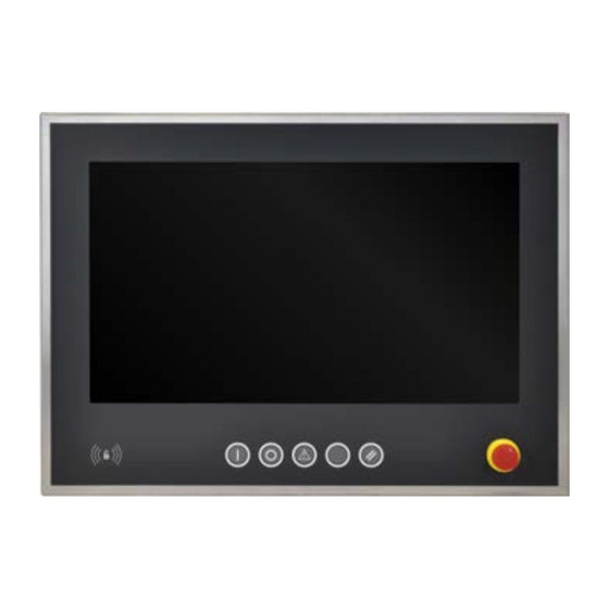
Technical data 4.1.6.3 AP99D - Features Automation Panels 5AP99D.156B-B62, 5AP99D.185B-B62 5AP99D.215C-B62 are equipped with the follow- ing interfaces and operating elements: • Rear USB interface • RFID read/write unit • 5 B&R illuminated ring keys • Emergency stop • Optional keys Information: Illuminated ring keys come with a standard label. - Page 62 Technical data Information: The USB interface on the panel takes up the USB2 interface on the link module. If the USB cable is unplugged, the USB interface is disabled. Depending on the transfer method (SDL or DVI operation), there are limitations regarding the transfer rate for interfaces USB1 and USB2.
- Page 63 Technical data 4.1.6.3.2 RFID read/write unit The RFID read/write unit is located on the front of the panel and can be used to read MIFARE and ISO 15693 tags. The following transponder tags can be used with this RFID read/write unit: Order number Short description 5A9010.43...
- Page 64 Technical data 4.1.6.3.3 B&R illuminated ring keys Each key and LED can be individually configured and adapted to the application. Various B&R tools are available for this purpose: • B&R Key Editor, B&R KCF Editor or B&R Control Center for Windows operating systems •...
- Page 65 Technical data 4.1.6.3.3.2 Visual Components (optional) T6 T7 T8 T9 T1/L1 T2/L2 T3/L3 T4/L4 T5/L5 NH = Alarm contact Figure 8: Keys and LEDs in the matrix When using the key or LED matrix (HMI → Runtime → Matrix) in VC, the corresponding offsets are assigned according to the following table: Key and LED matrix - Offset Offset...
- Page 66 Technical data 4.1.6.3.3.3 Direct wiring Keys and LEDs can optionally be wired directly. Figure 9: Key and LED assignments - Direct wiring 12-pin multipoint connector - Pinout Accessories 0TB1112.8010 RM 3.5 12-pin screw clamp terminal block, 1.5 mm² Description 24 VDC 24 V +25% T1_OUT T2_OUT...
- Page 67 Technical data 4.1.6.3.4 Emergency stop 4-pin multipoint connector - Pinout Accessories 0TB1104.8100 RM 3.5 mm, 4-pin cage clamp terminal block Description NC 11/12 NC 21/22 4.1.6.3.5 Connection for optional keys Connector pinout (5-pin connector) Accessories 0TB705.81 RM 3.5 mm, 5-pin cage clamp terminal block For the pinout for optional keys, see "Key and LED matrix - Offset"...
-
Page 68: Individual Components
Technical data 4.2 Individual components 4.2.1 Panels 4.2.1.1 5AP92D.1505-I00 4.2.1.1.1 General information • Single-touch (analog, resistive), with fully laminated panel overlay (shatter protection) • IP69K protection (front), IP66 protection (back) • Front and housing made of stainless steel (hygienic design, no dirt-collecting edge) •... - Page 69 Technical data Model number 5AP92D.1505-I00 Front Frame Stainless steel 1.4301, smoothed Panel overlay Material Polyester Design B&R design Gasket Silicone profile gasket between front and cover Flange output Rear Dimensions Width 420 mm Height 344 mm Depth 71.5 mm Weight 6,700 g At 25°C ambient temperature.
-
Page 70: 5Ap92D.1906-I00
Technical data 4.2.1.2 5AP92D.1906-I00 4.2.1.2.1 General information • Single-touch (analog, resistive), with fully laminated panel overlay (shatter protection) • IP69K protection (front), IP66 protection (back) • Front and housing made of stainless steel (hygienic design, no dirt-collecting edge) • B&R panel overlay design, edge protection for the panel overlay •... - Page 71 Technical data Model number 5AP92D.1906-I00 Front Frame Stainless steel 1.4301, smoothed Panel overlay Material Polyester Design B&R design Gasket Silicone profile gasket between front and cover Flange output Rear Dimensions Width 514 mm Height 420 mm Depth 78.5 mm Weight 10,000 g Table 10: 5AP92D.1906-I00 - Technical data At 25°C ambient temperature.
-
Page 72: 5Ap93D.185B-B62
Technical data 4.2.1.3 5AP93D.185B-B62 4.2.1.3.1 General information • Multi-touch (projected capacitive); with fully-laminated panel overlay (shatter protection) • IP69K protection (front), IP66 protection (back) • Front and housing made of stainless steel (hygienic design, no dirt-collecting edge) • B&R panel overlay design, edge protection for the panel overlay •... - Page 73 Technical data Model number 5AP93D.185B-B62 Flange output Upper and lower Dimensions Width 507.2 mm Height 327.8 mm Depth 141.6 mm Weight 8,800 g At 25°C ambient temperature. Reducing the brightness by 50% can increase the half-brightness time by approximately 50%. Under a steam jet, however, the structured coating on the front can become loose.
-
Page 74: 5Ap93D.240C-B62
Technical data 4.2.1.4 5AP93D.240C-B62 4.2.1.4.1 General information • Multi-touch (projected capacitive); with fully-laminated panel overlay (shatter protection) • IP69K protection (front), IP66 protection (back) • Front and housing made of stainless steel (hygienic design, no dirt-collecting edge) • B&R panel overlay design, edge protection for the panel overlay •... - Page 75 Technical data Model number 5AP93D.240C-B62 Flange output Upper and lower Dimensions Width 630.2 mm Height 396.8 mm Depth 141.91 mm Weight 12,300 g At 25°C ambient temperature. Reducing the brightness by 50% can increase the half-brightness time by approximately 50%. Under a steam jet, however, the structured coating on the front can become loose.
-
Page 76: 5Ap99D.156B-B62
Technical data 4.2.1.5 5AP99D.156B-B62 4.2.1.5.1 General information • Multi-touch (projected capacitive); with fully-laminated panel overlay (shatter protection) • Protection: IP69K (front), IP66 (back) • Front/Housing made of stainless steel (hygienic design, no dirt-collecting edge) • B&R panel overlay design, edge protection for the panel overlay •... - Page 77 Technical data Model number 5AP99D.156B-B62 Keys Illuminated ring keys 5x B&R illuminated ring keys Illuminated ring keys Color 4x red, green, yellow, white 1x red, green, yellow, blue Features Emergency stop Type Schlegel FRVK series Contact element 2x normally closed contact, 1x normally open contact Optional operating elements Quantity 1x prepared cutout...
- Page 78 Technical data 4.2.1.5.4 Dimensions Figure 14: 5AP99D.156B-B62 - Dimensions Information: 2D and 3D diagrams (DXF and STEP formats) can be downloaded from the B&R website (www.br- automation.com). Automation Panel 9xD - Hygienic design User's manual V 1.80...
-
Page 79: 5Ap99D.185B-B62
Technical data 4.2.1.6 5AP99D.185B-B62 4.2.1.6.1 General information • Multi-touch (projected capacitive); with fully-laminated panel overlay (shatter protection) • Protection: IP69K (front), IP66 (back) • Front/Housing made of stainless steel (hygienic design, no dirt-collecting edge) • B&R panel overlay design, edge protection for the panel overlay •... - Page 80 Technical data Model number 5AP99D.185B-B62 Features Emergency stop Type Schlegel FRVK series Contact element 2x normally closed contact, 1x normally open contact Optional operating elements Quantity 2x prepared cutout Operating conditions Pollution degree per EN 61131-2 Pollution degree 2 Suitable for hygienic applications Degree of protection per EN 60529 Back: IP66 (only with flange installed) Front: IP69K...
- Page 81 Technical data 4.2.1.6.4 Dimensions (4x) 141.6 507.2 61.53 411.6 26.75 321.49 253.9 80.6 Figure 15: 5AP99D.185B-B62 - Dimensions Information: 2D and 3D diagrams (DXF and STEP formats) can be downloaded from the B&R website (www.br- automation.com). Automation Panel 9xD - Hygienic design User's manual V 1.80...
-
Page 82: 5Ap99D.215C-B62
Technical data 4.2.1.7 5AP99D.215C-B62 4.2.1.7.1 General information • Multi-touch (projected capacitive); with fully-laminated panel overlay (shatter protection) • Protection: IP69K (front), IP66 (back) • Front/Housing made of stainless steel (hygienic design, no dirt-collecting edge) • B&R panel overlay design, edge protection for the panel overlay •... - Page 83 Technical data Model number 5AP99D.215C-B62 Features Emergency stop Type Schlegel FRVK series Contact element 2x normally closed contact, 1x normally open contact Optional operating elements Quantity 2x prepared cutout Operating conditions Pollution degree per EN 61131-2 Pollution degree 2 Suitable for hygienic applications Degree of protection per EN 60529 Back: IP66 (only with flange installed) Front: IP69K...
-
Page 84: Link Modules
Technical data 4.2.2 Link modules 4.2.2.1 5DLSDL.1001-00 4.2.2.1.1 General information • Link module for Automation Panel 9x3/1000/5000 • 1x SDL/DVI Panel In interface • 2x USB 2.0 type A • 1x USB In (USB type B) • 1x RS232 interface •... - Page 85 Technical data Model number 5DLSDL.1001-00 Operating conditions Pollution degree per EN 61131-2 Pollution degree 2 Mechanical properties Dimensions Width 190 mm Height 110 mm Depth 23.6 mm Weight 538 g The brightness controls can be used to set the brightness of the backlight on the Automation Panel in DVI operation. Yes, but applies only if all components installed in the complete system have this certification and the complete system bears the corresponding mark.
-
Page 86: 5Dlsd3.1001-00
Technical data 4.2.2.2 5DLSD3.1001-00 4.2.2.2.1 General information • Link module for Automation Panel 9x3/1000/5000 • 1x SDL3 Panel In interface • 2x USB 2.0 type A 4.2.2.2.2 Order data Model number Short description Figure Link modules 5DLSD3.1001-00 Automation Panel link module - SDL3 receiver - For Automation Panel 923/933/1000 - For Automation Panel 5000 Required accessories Accessories... - Page 87 Technical data Model number 5DLSD3.1001-00 Electrical properties Nominal voltage 24 VDC ±25%, SELV Nominal current Max. 3 A Overvoltage category per EN 61131-2 Galvanic isolation Operating conditions Pollution degree per EN 61131-2 Pollution degree 2 Mechanical properties Dimensions Width 190 mm Height 110 mm Depth...
-
Page 88: 5Dlsd4.1001-00
Technical data 4.2.2.3 5DLSD4.1001-00 4.2.2.3.1 General information • Link module for Automation Panel 9x3/1000/5000 • 1x SDL4 Panel In interface • 2x USB 2.0 type A 4.2.2.3.2 Order data Model number Short description Figure Link modules 5DLSD4.1001-00 Automation Panel link module - SDL4 receiver - For Automation Panel 923/933/1000 - For Automation Panel 5000 Required accessories Accessories... - Page 89 Technical data Model number 5DLSD4.1001-00 Operating conditions Pollution degree per EN 61131-2 Pollution degree 2 Mechanical properties Dimensions Width 190 mm Height 110 mm Depth 23.6 mm Weight 525 g EN 60950 requirements must be observed; see section "+24 VDC power supply" of the data sheet. Automation Panel 9xD - Hygienic design User's manual V 1.80...
-
Page 90: System Units
Technical data 4.2.3 System units 4.2.3.1 5PPC2100.BYxx-000 4.2.3.1.1 General information PPC2100 system units consist of a CPU board, main memory and housing. It includes all interfaces; in addition, an interface option can be installed. The main memory is permanently soldered to the CPU board and cannot be replaced or upgraded. - Page 91 Technical data 4.2.3.1.3 Technical data Model number 5PPC2100. 5PPC2100. 5PPC2100. 5PPC2100. 5PPC2100. 5PPC2100. BY01-000 BY11-000 BY22-000 BY34-000 BY44-000 BY48-000 General information Cooling Passive via housing LEDs Power, CFast, Link, Run B&R ID code 0xE522 0xE524 0xE545 0xE547 0xE54B 0xED0B Power button Reset button Buzzer Certifications...
- Page 92 Technical data Model number 5PPC2100. 5PPC2100. 5PPC2100. 5PPC2100. 5PPC2100. 5PPC2100. BY01-000 BY11-000 BY22-000 BY34-000 BY44-000 BY48-000 Ethernet Quantity Variant RJ45, shielded Transfer rate 10/100/1000 Mbit/s Max. baud rate 1 Gbit/s Slots Interface option Electrical properties Nominal voltage 24 VDC ±25% Nominal current 3.5 A Inrush current...
-
Page 93: 5Ppc2200.Alxx-000
Technical data 4.2.3.2 5PPC2200.ALxx-000 4.2.3.2.1 General information PPC2200 system units consist of a CPU board, housing and mounting plate. It includes all interfaces; in addition, an interface option can be installed. The main memory is permanently soldered to the CPU board and cannot be replaced or upgraded. - Page 94 Technical data 4.2.3.2.3 Technical data Information: The following specified characteristic data, features and limit values are only valid for these individual components and may differ from those of the complete system. The data specified for the complete system applies to the complete system in which this individual component is used, for example. Model number 5PPC2200.AL02-000 5PPC2200.AL04-000...
- Page 95 Technical data Model number 5PPC2200.AL02-000 5PPC2200.AL04-000 5PPC2200.AL14-000 5PPC2200.AL18-000 Slots Interface option Electrical properties Nominal voltage 24 VDC ±25%, SELV Nominal current Max. 4 A Inrush current Typ. 5 A, max. 50 A for < 500 μs Overvoltage category per EN 61131-2 Galvanic isolation Operating conditions Pollution degree per EN 61131-2...
-
Page 96: Interface Options
Technical data 4.2.4 Interface options For information about the interface options available for PPC2x00 system units, see the respective system manual. These are available for download on the B&R website. • User's manual PPC2100SW1 • User's manual PPC2200SW Automation Panel 9xD - Hygienic design User's manual V 1.80... -
Page 97: Battery Compartment
Technical data 4.2.5 Battery compartment 4.2.5.1 5ACCBT01.0000-001 4.2.5.1.1 General information The lithium battery is needed to retain BIOS CMOS data and to back up the real-time clock (RTC). The battery is subject to wear and must be replaced if the battery capacity is insufficient (state "Bad"). 4.2.5.1.2 Order data Model number Short description... -
Page 98: Installation And Wiring
Installation and wiring 5 Installation and wiring 5.1 Important information for installation/commissioning The following must be taken into account when using a Rittal CP-S stainless steel flange (CP6664.500 or CP6664.000): Information: Before installing the Automation Panel 9xD on a swing arm system, it must be checked whether the sealing ring is installed on the flange of the AP9xD. - Page 99 Installation and wiring Swing arm connection 2. Remove the holding hooks and retaining straps and rotate the housing cover 180°. 3. After rotating that housing cover, attach it to the swing arm. 4. Install the retaining straps and holding books back on the housing cover (the holding hooks can also be installed before installation on the swing arm).
- Page 100 Installation and wiring 7. Wiring can now take place. The panel is then installed on the holding hooks of the housing cover. Make sure the retaining straps are not pinched. 8. Before screwing down the housing cover, make sure that the gasket is lined up with the knobs in the opening of the panel.
-
Page 101: Installing Optional Control Elements
Installation and wiring 5.3 Installing optional control elements Depending on the variant of the AP99D panels with hygienic design, 1 to 2 prepared cutouts are available to be equipped with optional operating elements. 1. Disconnect the power supply cable to the device (disconnect the power cable!). Disconnect from all sources and poles! 2. -
Page 102: Connecting To The Power Grid
Installation and wiring 5.4 Connecting to the power grid Danger! • The entire power supply must be disconnected and electrostatic discharge must take place on the housing or ground connection before removing any covers or components from the device and installing or removing any accessories, hardware or cables. •... -
Page 103: Connecting The Power Supply To A B&R Device
Installation and wiring 5.4.2 Connecting the power supply to a B&R device Danger! The entire power supply to the B&R device must be interrupted. Before connecting the power cable, it must be checked whether it has been disconnected from the voltage source (e.g. power supply). 1. -
Page 104: Grounding Concept - Functional Ground
Installation and wiring 5.4.3 Grounding concept - Functional ground Functional ground is a current path of low impedance between circuits and ground. It is used to improve immunity to interference, for example, and not as a protective measure. It serves only to divert interference, not to protect against contact with persons. -
Page 105: Connecting Cables
Installation and wiring 5.5 Connecting cables Information: B&R generally recommends connecting swing arm devices to the Automation PC via SDL4 in- stead of SDL. The Cat 6 / Cat 7 cables used with SDL4 are much easier to install and connect. When connecting or installing cables, the bend radius specification must be observed. -
Page 106: Commissioning
Commissioning 6 Commissioning 6.1 Basic information Before the device is started up, it must be gradually adapted to room temperature! 6.2 Switching on the device for the first time 6.2.1 General information before switching on the device Checklist Before the device is started up for the first time, the following points must be checked: •... -
Page 107: Touch Screen Calibration
Commissioning 6.3 Touch screen calibration B&R touch screen devices are equipped with a B&R touch controller that supports hardware calibration. This means that these devices are pre-calibrated at the factory. This feature offers great advantages especially for replacement parts since recalibration is usually no longer required when replacing a device (identical model/type). We still recommend calibration for best results and to adapt the touch screen to the needs of the user. -
Page 108: Multi-Touch (Projected Capacitive - Pct)
Commissioning 6.3.2 Multi-touch (projected capacitive - PCT) 6.3.2.1 Windows 10 IoT Enterprise 2016 LTSB Microsoft multi-touch drivers are installed on the device during installation of Windows 10 IoT Enterprise 2016 LTSB. After successful installation of Windows 10 IoT Enterprise 2016 LTSB, the device is immediately ready for operation. -
Page 109: Display Brightness Control
Commissioning 6.4 Display brightness control In SDL, SDL3 or SDL4 operation, the brightness of the display can be configured using the B&R Control Center on the connected B&R industrial PC, for example. In DVI operation, the brightness can only be controlled using the two brightness controls provided on the SDL/DVI receiver. -
Page 110: Software
Software 7 Software 7.1 Upgrade information Warning! The BIOS and firmware on B&R devices must always be kept up to date. New versions can be down- loaded from the B&R website (www.br-automation.com). 7.1.1 Automation Panel firmware upgrade With Firmware upgrade (Automation Panel, SDL3 Converter, SLD4 converter), it is possible to update the firmware of several controllers (SDLR, SDL3R, SDL4R, SDL3 Converter, SDL4 Converter) depending on the variant of the system. -
Page 111: Automation Device Interface (Adi)
Software 7.2 Automation Device Interface (ADI) The Automation Device Interface (ADI) enables access to specific functions of B&R devices. 7.2.1 ADI driver 7.2.1.1 Installation The ADI driver is included in most B&R Windows operating systems or can be installed on request. The ADI driver (also includes the Control Center) and user documentation can be downloaded at no cost from the Downloads section of the B&R website (www.br-automation.com). -
Page 112: Adi Development Kit
Software 7.2.2 ADI Development Kit This software allows ADI functions to be accessed from Windows applications created with Microsoft Visual Studio, for example: Features: • Header files and import libraries • Help files • Example projects • ADI DLL: For testing applications if no ADI driver is installed. The appropriate ADI driver for the device must be installed on the mentioned product family. -
Page 113: Adi .Net Sdk
Software 7.2.3 ADI .NET SDK This software allows ADI functions to be accessed from .NET applications created with Microsoft Visual Studio. Features: • ADI .NET class library • Help files (in English) • Sample projects and code snippets • ADI DLL: For testing applications if no ADI driver is installed. The appropriate ADI driver for the device must be installed on the mentioned product family. -
Page 114: Key Editor
Software 7.3 Key Editor A frequently occurring requirement for panels is adapting function keys and LEDs to the application software. With the Key Editor, individual adaptation to the application is possible quickly and easily. Features: • Configuration of normal keys like on a keyboard (A, B, C, etc.) •... -
Page 115: Rfid Read/Write Transponder Unit
Software 7.4 RFID read/write transponder unit 7.4.1 Commissioning 7.4.1.1 Connection The reader can be used on any conventional type A USB interface that fulfills the specifications listed in the technical data for 5E9020.29. 7.4.1.2 Supported operating systems • Windows XP Professional •... -
Page 116: Rfid Command Set
Software 7.4.1.6 RFID command set The transponder reads and writes MIFARE and ISO 15693 tags. The corresponding commands and parameters are valid depending on the tag being used. When a tag comes within range of the antenna, the PiccSelect message and serial number of the tag are output. -
Page 117: Mifare
Software Procedure in Windows: 1) Enter command "Firmware_Upgrade" to put the transponder reader in upgrade mode. 2) Depending on the Windows system settings, the transponder reader will automatically be registered as a USB mass storage device. 3) A new drive will appear in Windows Explorer (e.g. D:\). 4) Open the new drive in Windows Explorer. -
Page 118: Access Rights And Memory Organization
Software Default key (when tags are delivered): 0xFF FF FF FF FF FF Up to 16 keys (0 to 15) can be stored in EEPROM for each key (A and B). 7.4.3.3 Access rights and memory organization The tag is divided into 16 sectors of 4 blocks each. Each block contains 16 bytes. The 4th block in each sector contains the keys and access rights for the respective sector (sector trailer). -
Page 119: Access Rights
Software 7.4.3.5 Access rights There are various options for parameter 2 depending on the configuration. MIFARE access rights (parameter 2) Config Key_CMD Key_EEPROM Key_TEMP Para2 6-byte key Sector for key in reader's EEP- Uses the temporarily stored key: Dummy value (0-63) Table 37: MIFARE access rights (parameter 2) "A"... -
Page 120: Mifare Commands - Examples
Software 7.4.3.6 MIFARE commands - Examples Befehl: write,a,0,5,0123456789ABCDEF0123456789ABCDEF Antwort: Command write -> Data in sector 1 Block 5 written=0123456789ABCDEF0123456789ABCDEF Befehl: read,a,0,5 Antwort: Command read -> Data in block 5 in HEX=0123456789ABCDEF0123456789ABCDEF Befehl: Initzero,a,0,8 Antwort: Command initzero -> Data in sector 2 Block 8 written=00000000FFFFFFFF0000000000FF00FF Befehl: Incr,a,0,8,8,2 Antwort:... -
Page 121: Memory Organization
Software Command Description Parameter 1 Parameter 2 Parameter 3 Parameter 4 Parameter 5 Set_DSFID Writes the DSFID value Flags (flag) 1-byte value Lock_Block Enables write protection for a block Flags (flag) Target block Lock_AFI Sets AFI write protection Flags (flag) Lock_DSFID Sets DSFID write protection Flags (flag) -
Page 122: Flag Definitions
Software 7.4.4.3 Flag definitions Request Flag Bits 1 to 4 Flag Name Value Description Subcarrier flag A single subcarrier is used by the flag Two subcarriers are used by the flag Data rate flag Low data rate High data rate Inventory flag Flags 5 to 8 meaning in following tables (points to table "Request Flag Bits 5 to 8 when inventory... -
Page 123: Iso 15693 Commands - Examples
Software 7.4.4.4 ISO 15693 commands - Examples 7.4.4.4.1 Inventory flags [hex]: 0x02 = High Data rate 0x04 = Inventory 0x10 = AFI value is set 0x20 = Single slot afi [dec]: AFI value if 0x10 set in the flags bitlength [dec]: Bit length of the subsequent UID mask. -
Page 124: Error Codes
Software 7.4.5 Error codes 7.4.5.1 Error messages and error numbers Operating errors Value Name Description ERR_NONE No errors (OK) ERR_OTHER Miscellaneous operating error, unrecognized command ERR_PARAMETER Incorrect number of parameters ERR_AUTH Authentication error (A or B) ERR_SECTOR Invalid range for sector (0-63) ERR_BLOCK_SRC Invalid range for source block (0-255) ERR_WRITE... - Page 125 Software RFID stack errors can be queried using command "show_status". Each error number consists of a high byte (stack components) and a low byte (errors). Command "show_error" allows the error to be evaluated in detail. (for exam- ple: ISO15693 error codes, see )"Response Flags &...
- Page 126 Software Error messages - RFID stack HIGH byte Value Name Description 0x00XX PH_COMP_GENERIC Generic Component Code 0x01XX PH_COMP_BAL BAL Component Code 0x02XX PH_COMP_HAL HAL Component Code 0x03XX PH_COMP_PAL_ISO14443P3A ISO14443-3A PAL-Component Code 0x04XX PH_COMP_PAL_ISO14443P3B ISO14443-3B PAL-Component Code 0x05XX PH_COMP_PAL_ISO14443P4A ISO14443-4A PAL-Component Code 0x06XX PH_COMP_PAL_ISO14443P4 ISO14443-4 PAL-Component Code...
-
Page 127: Standards And Certifications
Standards and certifications 8 Standards and certifications 8.1 Directives and declarations 8.1.1 CE marking All directives applicable to the respective product and their harmonized EN standards are met. 8.1.2 EMC Directive These devices meet the requirements of EC directive "2014/30/EU Electromagnetic compatibility" and are designed for the following application areas: EN 61131-2:2007 + Programmable controllers - Part 2: Equipment requirements and tests... -
Page 128: Ul Certification
Standards and certifications 8.2.1 UL certification Products with this mark are tested by Underwriters Laboratories and listed as "indus- trial control equipment". The mark is valid for the USA and Canada and facilitates the certification of your machines and systems in this economic area. Underwriters Laboratories (UL) per standards UL 61010-1 and UL 61010-2-201 Canadian (CSA) standard per C22.2 No. -
Page 129: Accessories
Accessories 9 Accessories The following accessories have undergone functional testing by B&R in connection with the device used and can be operated with this device. Possible limitations regarding operation with individual components other than the complete system must be taken into account, however. All individual specifications of the components must be observed when operating the complete system. -
Page 130: Terminal Block Power Supply
Accessories 9.3 Terminal block power supply 9.3.1 0TB103.9x 9.3.1.1 Order data Model number Short description Figure Accessories 0TB103.9 Connector 24 VDC - 3-pin, female - Screw clamp terminal block 3.31 mm² 0TB103.91 Connector 24 VDC - 3-pin, female - Cage clamp terminal block 3.31 mm²... -
Page 131: Cage Clamp Terminal Block For Wiring Emergency Stop
Accessories 9.4 Cage clamp terminal block for wiring emergency stop 9.4.1 0TB1104.8100 9.4.1.1 General information This 1-row, 4-pin cage clamp terminal block is used to connect to various B&R modules. 9.4.1.2 Order data Model number Short description Figure Accessories 0TB1104.8100 Accessory terminal block (3.5), 4-pin, cage clamp terminal block 1.5 mm², protected against vibration by the screw flange 9.4.1.3 Technical data... -
Page 132: Screw Clamp Terminal Block For Wiring B&R Illuminated Ring Keys
Accessories 9.5 Screw clamp terminal block for wiring B&R illuminated ring keys 9.5.1 0TB1112.8010 9.5.1.1 General information This 1-row, 12-pin screw clamp terminal block is used to connect to various B&R modules. 9.5.1.2 Order data Model number Short description Figure Accessories 0TB1112.8010 12-pin accessory field terminal, 1.5 mm screw clamp terminal... -
Page 133: Usb Flash Drives
Accessories 9.6 USB flash drives 9.6.1 5MMUSB.xxxx-01 9.6.1.1 General information USB flash drives are easily replaceable storage media. Due to the fast data transfer (USB 2.0), USB flash drives offer optimal values for use as portable storage media. Without additional drivers, the USB flash drive immediately reports itself as another drive from which data can be read or to which data can be written (hot plugging). -
Page 134: Temperature/Humidity Diagram
Accessories Model number 5MMUSB.2048-01 5MMUSB.4096-01 Support Operating systems Windows 10 IoT Enterprise LTSB 64-bit Windows Embedded 8.1 Industry Pro 32-bit Windows Embedded 8.1 Industry Pro 64-bit Windows 7 32-bit Windows 7 64-bit Windows Embedded Standard 7 32-bit Windows Embedded Standard 7 64-bit Windows XP Professional Windows XP Embedded Windows 2000... -
Page 135: 5Mmusb.032G-02
Accessories 9.6.2 5MMUSB.032G-02 9.6.2.1 General information USB flash drives are easily replaceable storage media. Due to the fast data transfer (USB 3.0), USB flash drives offer optimal values for use as portable storage media. Without additional drivers, the USB flash drive immediately reports itself as another drive from which data can be read or to which data can be written (hot plugging). -
Page 136: Temperature/Humidity Diagram
Accessories Model number 5MMUSB.032G-02 Vibration Operation 7 to 2000 Hz: 20 g Storage 7 to 2000 Hz: 20 g Transport 7 to 2000 Hz: 20 g Shock Operation 1500 g, 0.5 ms Storage 1500 g, 0.5 ms Transport 1500 g, 0.5 ms Elevation Operation Max. -
Page 137: Line Filter
Accessories 9.7 Line filter 9.7.1 5AC804.MFLT-00 9.7.1.1 General information Line filter 5AC804.MFLT-00 may be necessary to satisfy maritime requirements regarding conducted disturbances in supply lines in accordance with the GL (Germanischer Lloyd) or DNVGL. The line filter should be installed as close to the end device as possible; the supply line from the end device to the line filter should be kept as short as possible. -
Page 138: Dimensions
Accessories Model number 5AC804.MFLT-00 Dimensions Width 54 mm Length 94 mm Depth 32.15 mm Weight 205 g Yes, but applies only if all components installed in the complete system have this certification and the complete system bears the corresponding mark. Yes, but applies only if all components installed in the complete system have this certification and are listed on the associated DNV GL certificate for the product family. -
Page 139: Replacement Screws
Accessories 9.8 Replacement screws 9.8.1 5A9000.75, 5A9000.76 9.8.1.1 General information To ensure leak tightness, new screws must be used after the hygienic panels have been removed again. Torx or slotted screws are available. 9.8.1.2 Order data Model number Short description Figure Accessories 5A9000.75... -
Page 140: Replacement Gaskets
Accessories 9.9 Replacement gaskets 9.9.1 5A9000.73, 5A9000.74 9.9.1.1 General information Replacement gaskets are available as optional accessories. 9.9.1.2 Order data Model number Short description Figure Accessories 5A9000.73 cHMI housing replacement gasket 15" 5A9000.74 cHMI housing replacement gasket 19" 9.9.1.3 Technical data Model number 5A9000.73 5A9000.74... -
Page 141: Replacement Gaskets
Accessories 9.10 Replacement gaskets 9.10.1 5A9000.D3, 5A9000.D4, 5A9000.D5, 5A9000.D6, 5A9000.D7 9.10.1.1 General information Replacement gaskets are available as optional accessories. 9.10.1.2 Order data Model number Short description Figure Accessories 5A9000.D3 cHMI replacement gasket for 5AP99D.156B-B62 5A9000.D4 cHMI replacement gasket for 5AP93D.185B-B62 5A9000.D5 cHMI replacement gasket for 5AP99D.185B-B62 5A9000.D6... -
Page 142: Replacement Parts
Accessories 9.11 Replacement parts The following replacement parts can be ordered for the Panel PC 2100 swing arm and Panel PC 2200 swing arm: • Mounting screws for PPC2100 • Mounting screws for PPC2200 • Slot cover for interfaces • Cover for CFast slot •... -
Page 143: Maintenance
Maintenance 10 Maintenance The following chapter describes the maintenance work that can be carried out by a qualified and trained end user. Information: Only components approved by B&R are permitted to be used for maintenance work. 10.1 Cleaning Danger! In order to prevent unintentional operation (by touching the touch screen or keys), the device is only permitted to be cleaned when the power is switched off. -
Page 144: User Tips For Increasing The Service Life Of The Display
Maintenance 10.2 User tips for increasing the service life of the display 10.2.1 Backlight The service life of the backlight is specified by its "half-brightness time". An operating time of 50,000 hours would mean that the display brightness would still be 50% after this time. 10.2.1.1 Measures to maintain backlight service life •... -
Page 145: Repairs/Complaints And Replacement Parts
Maintenance 10.5 Repairs/Complaints and replacement parts Danger! Unauthorized opening or repair of a device may result in personal injury and/or serious damage to property. Repairs are therefore only permitted to be carried out by authorized qualified personnel at the manufacturer's premises. To process a repair/complaint, a repair order or complaint must be created via the B&R Material Return Portal on the B&R website (www.br-automation.com). -
Page 146: Mtcx
Appendix A Appendix A A.1 MTCX The MTCX controller (FPGA processor) is located on the mainboard (component of every system unit) of the : The MTCX is responsible for the following monitoring and control functions: • Power failure logic and power on logic (power OK sequencing) •... -
Page 147: Chemical Resistance
Appendix A A.4 Chemical resistance Panels are manufactured with the Autotex panel overlay: Stainless steel front Touch screen Panel overlay Figure 23: Stainless steel front with Autotex panel overlay Automation Panel 9xD - Hygienic design User's manual V 1.80... -
Page 148: Autotex Panel Overlay (Polyester)
Appendix A A.4.1 Autotex panel overlay (polyester) Unless otherwise specified, the panel overlay is resistant to the following chemicals per DIN 42115 Part 2 when exposed for up to 24 hours without visible changes: • Acetaldehyde • Diesel • Sodium carbonate •... -
Page 149: Touch Screen
Appendix A A.4.2 Touch screen AMT touch screen (single-touch) Unless otherwise specified, the AMT touch screen is resistant to the following chemicals when exposed for up to 1 hour (at 25°C) with no visible changes: • Acetone • Antifreeze • Methyl ethyl ketone •... -
Page 150: Features
Appendix A A.B Features A.B.1 RFID read/write transponder unit RFID read/write transponder unit Vendor ID 0x1FC9 Example image Frequency 13.56 MHz Read/Write transponder unit For I-Code SLI transponder, amplitude modulation and MIFARE Classic Quantity Standard ISO 15693, MIFARE Classic Read/Write range in air Approx. -
Page 151: Touch Screen
Appendix A A.C Touch screen A.C.1 Touch screen (single-touch) A.C.1.1 Technical data Information: The following specified characteristic data, features and limit values are only valid for these individual components and may differ from those of the complete system. The data specified for the complete system applies to the complete system in which this individual component is used, for example. -
Page 152: A.c.2.2 Temperature/Humidity Diagram
Appendix A Model number Touchscreen 3M Operating conditions Activation Finger, thin glove Ambient conditions Temperature Operation -10 to 70°C Storage -40 to 70°C Transport -40 to 70°C Relative humidity Operation Up to 90% at max. 35°C, see diagram for > 35°C. Storage Up to 90% at max. -
Page 153: Led "S/E" (Led "Status/Error")
Appendix A A.7 LED "S/E" (LED "Status/Error") This LED is a green/red dual LED and indicates the state of the POWERLINK interface. The LED states have a different meaning depending on the operating mode of the POWERLINK interface. A.7.1 Ethernet mode In this mode, the interface is operated as an Ethernet interface. - Page 154 Appendix A LED "S/E" Green Description Single flash Mode: PRE_OPERATIONAL_1 (approx. 1 Hz) The interface is in mode PRE_OPERATIONAL_1. Managing node (MN) The MN is in "reduced cycle" mode. The CNs are configured in this mode. Cyclic communication is not yet taking place. Controlled node (CN) The CN can be configured by the MN in this mode.
-
Page 155: System Stop Error Codes
Appendix A A.7.3 System stop error codes A system stop error can occur due to incorrect configuration or defective hardware. The error code is indicated by LED "S/E" blinking red. The blinking signal of the error code consists of 4 switch-on phases with short (150 ms) or long (600 ms) duration. -
Page 156: Environmentally Friendly Disposal
Environmentally friendly disposal 12 Environmentally friendly disposal All programmable logic controllers, operating and monitoring devices and uninterruptible power supplies from B&R are designed to have as little impact on the environment as possible. 12.1 Separation of materials To ensure that devices can be recycled in an environmentally friendly manner, it is necessary to separate out the different materials. - Page 157 Publishing information Automation Panel 9xD - Hygienic design User's manual V 1.80...
- Page 158 Publishing information Publishing information B&R Industrial Automation GmbH B&R Strasse 1 5142 Eggelsberg Austria Telephone: +43 7748 6586-0 Fax: +43 7748 6586-26 office@br-automation.com Automation Panel 9xD - Hygienic design User's manual V 1.80...
Need help?
Do you have a question about the Automation Panel 9 D Series and is the answer not in the manual?
Questions and answers