Table of Contents
Advertisement
Quick Links
Automation Panel 5000
User's manual
Version: 2.11 (July 2020)
Order no.: MAAP5000-ENG
Translation of the original documentation
All values in this manual are current as of its creation. We reserve the right to change the contents of this manual
without notice. B&R Industrial Automation GmbH is not liable for technical or editorial errors and defects in this
manual. In addition, B&R Industrial Automation GmbH assumes no liability for damages that are directly or indirectly
attributable to the delivery, performance or use of this material. We point out that the software and hardware
designations and brand names of the respective companies used in this document are subject to general trademark,
brand or patent protection.
Advertisement
Table of Contents

Related Manuals for B&R Automation Panel 5000


Summary of Contents for B&R Automation Panel 5000
- Page 1 Automation Panel 5000 User's manual Version: 2.11 (July 2020) Order no.: MAAP5000-ENG Translation of the original documentation All values in this manual are current as of its creation. We reserve the right to change the contents of this manual without notice. B&R Industrial Automation GmbH is not liable for technical or editorial errors and defects in this manual.
-
Page 2: Table Of Contents
4.1.4.3 Vibration and shock........................... 46 4.1.4.4 Degree of protection.......................... 46 4.1.5 Device interfaces............................. 48 4.1.5.1 SDL/DVI receiver (5DLSDL.1001-00)....................48 4.1.5.2 SDL3 receiver (5DLSD3.1001-00)..................... 54 4.1.5.3 SDL4 receiver (5DLSD4.1001-00)..................... 58 4.1.6 Equipping panels with expansion units....................62 Automation Panel 5000 User's manual V2.11... - Page 3 4.2.5.6 5ACCKPSx.xxxx-xxx........................139 4.2.6 Handles..............................140 4.2.6.1 5ACCHD0x.xxxx-000........................140 5 Installation and wiring..................142 5.1 Basic information............................142 5.2 Automation Panel 5000 - Installation......................144 5.2.1 Installation with flange........................... 144 5.3 Removing the mounting unit cover......................146 5.4 Removing the link module.......................... 147 5.5 Installing accessories..........................148 5.5.1 Installing the handles..........................148...
- Page 4 7.2 Multi-touch drivers............................174 7.3 Automation Runtime............................175 7.3.1 General information..........................175 7.3.2 System requirements..........................175 7.4 Control Center.............................176 7.4.1 Functions............................... 176 7.4.2 Installation..............................176 7.5 ADI Development Kit..........................177 7.6 ADI .NET SDK............................178 7.7 Key Editor..............................179 Automation Panel 5000 User's manual V2.11...
- Page 5 10.1.1 CE marking............................191 10.1.2 Radio Equipment Directive (RED).......................191 10.1.3 EMC Directive............................192 10.2 Certifications..............................193 10.2.1 UL certification............................. 193 10.2.2 EAC..............................193 10.2.3 KC................................ 193 10.2.4 RCM..............................193 10.3 Notes for the manual pursuant to radio approval..................194 Automation Panel 5000 User's manual V2.11...
- Page 6 D.9.6.1 Selector switch RAFIX 22 FS+, 1.30.272.102/2200............... 211 D.9.6.2 Switching element RAFIX FS, 1.20.126.102/9000................211 D.9.7 5ACCSE00.0005-000..........................212 D.9.7.1 USB extension RAFIX 22 FS+, 9.30.279.003/0700................ 212 Appendix E Touch screen..................213 E.1 Touch screen AMT 5-wire (single-touch)....................213 E.1.1 Technical data............................213 Automation Panel 5000 User's manual V2.11...
- Page 7 Table of contents E.1.2 Temperature/Humidity diagram......................213 E.2 3M touch screen (multi-touch generation 3)....................214 E.2.1 Technical data............................214 E.2.2 Temperature/Humidity diagram......................214 Automation Panel 5000 User's manual V2.11...
-
Page 8: Introduction
Temperature/Humidity diagrams ° Block diagrams ° Device interfaces • Updated the following: ° USB interfaces under "Individual components" > "Mounting units" ° Information about SDL4 modules ° Swivel-tilt flange ° Expansion units 5ACCKP03.xxxx-000 5ACCKP05.xxxx-000 Automation Panel 5000 User's manual V2.11... - Page 9 ° "ADI .NET SDK" on page 178 ° "Key Editor" on page 179 ° "KCF Editor" on page 180 ° "HMI Service Center" on page 181 ° "Repairs/Complaints and replacement parts" on page 183 Automation Panel 5000 User's manual V2.11...
- Page 10 "5ACCSE00.0000-000" on page 204 ° "5ACCSE00.0001-000" on page 207 ° "5ACCSE00.0002-000" on page 208 ° "5ACCSE00.0003-000" on page 210 ° "5ACCSE00.0004-000" on page 211 ° "5ACCSE00.0005-000" on page 212 1.00 June 2016 • First version Automation Panel 5000 User's manual V2.11...
-
Page 11: Information About This Document
±0.1 mm Over 6 to 30 mm ±0.2 mm Over 30 to 120 mm ±0.3 mm Over 120 to 400 mm ±0.5 mm Over 400 to 1000 mm ±0.8 mm Table 2: Nominal dimension ranges Automation Panel 5000 User's manual V2.11... -
Page 12: General Safety Guidelines
Electronic devices are generally not failsafe. If the programmable logic controller, operating or control device or uninterruptible power supply fails, the user is responsible for ensuring that connected devices (such as motors) are brought to a safe state. Automation Panel 5000 User's manual V2.11... -
Page 13: Transport And Storage
Automation Panels or Power Panels are protected on the front against the ingress of dust and moisture when installed correctly (e.g. cutout installation). The back of all devices must be protected against the ingress of dust and moisture, however, or the dust deposits must be removed at suitable intervals. Automation Panel 5000 User's manual V2.11... -
Page 14: Programs, Viruses And Malicious Programs
The term "control systems" refers to all types of B&R products such as controllers (e.g. X20), HMI systems (e.g. Power Panel T30), process control systems (e.g. APROL) and supporting systems such as engineering workstations with Automation Studio. Automation Panel 5000 User's manual V2.11... -
Page 15: System Overview
3.2 Easy customization The Automation Panel 5000 can be used as a remote panel or part of a Panel PC. For this, the panel is either equipped with a receiver for Smart Display Link (SDL), SDL3 or SDL4, or a PC unit is attached. The operator panel is always identical. -
Page 16: Description Of Individual Modules
3.3.1 AP5000 panels The AP5000 series forms the basis for the Automation Panel 5000 and two Panel PC variants: Panel PC 2100 or Panel PC 2200 swing arm device with Automation Panel 5000. They consist of a display and touch screen. Different display sizes, touch screen technologies, mounting systems and panels with operating elements are available. -
Page 17: Flanges
Expansion covers have cutouts that can be used to install the desired operating elements at a later time. The operating elements are already integrated in expansion units. 3.3.6 Handles Handles can be installed on the sides of the panel to enable comfortable, ergonomic operation. Automation Panel 5000 User's manual V2.11... -
Page 18: Configuration
System overview 3.4 Configuration The following individual components are mandatory for operation as an Automation Panel 5000: • Panel • Link module • Swing arm mounting unit or VESA • Flange (swing arm mounting unit only) • Expansion unit (only for AP5230) -
Page 19: Overview
Automation Panel link module - SDL4 receiver - For Automation Panel 923/933/1000 - For Automation Panel 5000 5DLSDL.1001-00 Automation Panel link module - SDL/DVI receiver - For Automation Panel 923/933/1000 - For Automation Panel 5000 Automation Panel 5000 User's manual V2.11... - Page 20 AP5000 swing arm mounting unit - 2x rear USB interface USB accessories 5MMUSB.032G-02 USB 3.0 flash drive 32 GB MLC 5MMUSB.2048-01 USB 2.0 flash drive 2048 MB B&R 5MMUSB.4096-01 USB 2.0 flash drive 4096 MB B&R Automation Panel 5000 User's manual V2.11...
-
Page 21: Technical Data
✓ ✓ USB1, USB2 USB 1.1 COM interface for touch Grounding screen Maximum cable length: 30 m Requirements • Automation Panel with SDL/DVI receiver • B&R industrial PC with SDL interface • SDL cable Automation Panel 5000 User's manual V2.11... - Page 22 USB 2.0 COM interface for touch Grounding screen Maximum cable length: 5 m Requirements • Automation Panel with SDL/DVI receiver • B&R industrial PC with SDL interface • SDL cable, USB type A/B cable Automation Panel 5000 User's manual V2.11...
-
Page 23: Dvi Operation
USB 2.0 COM interface for touch Grounding ✓ screen Maximum cable length: 5 m Requirements • Automation Panel with SDL/DVI receiver • B&R industrial PC with DVI interface • DVI cable, USB type A/B cable Automation Panel 5000 User's manual V2.11... - Page 24 • Data from operating elements is not transferred. • Service and diagnostic data is not transferred. • The maximum cable length is limited to 5 m. • Upgrading the firmware of Automation Panels is not possible. Automation Panel 5000 User's manual V2.11...
-
Page 25: Sdl3 Operation
° No SDL3/SDL4 cable is connected. ° There is no connection established yet between the SDL3 link module and SDL3 transmitter. This behavior can be avoided by appropriate configuration in BIOS or via the graphics driver. Automation Panel 5000 User's manual V2.11... -
Page 26: Sdl4 Operation
✓ SDL4 interface USB1, USB2 USB 2.0 Power supply Grounding Maximum cable length for SDL4: 100 m Requirements • Automation Panel with SDL4 receiver • B&R industrial PC with SDL4 interface • SDL3/SDL4 cable Automation Panel 5000 User's manual V2.11... - Page 27 • A maximum of two USB hubs with up to eight ports per hub is supported. • A maximum of six additional USB devices can be connected. • Maximum permissible USB endpoints: Endpoints Transfer rate of the devices High speed Full speed / Low speed Automation Panel 5000 User's manual V2.11...
-
Page 28: Electrical Properties
The following block diagram shows the simplified structure of the 55DLSD4.1001-00 SDL4 receiver link module. Power Panel DDC SDL FPGA Serial front IF LVDS Buffering LVDS SDL4 decoder converter USB hub Power Type A Type A LED "Link" LED "Status" Automation Panel 5000 User's manual V2.11... -
Page 29: Power Calculation
0.20 W 1.90 W Example 24.0" panel 5AP5230.240C-000 29.5 W 29.5 W 24.0" 5ACCKP01.240C-000 expansion unit 0.7 W 0.7 W 5DLSDL.1001-00 SDL/DVI receiver 8.6 W (with USB consumer) 8.6 W Total max.: 38.8 W Automation Panel 5000 User's manual V2.11... -
Page 30: Mechanical Properties
18.5" multi-touch 5AP5130.185B-000 23.5 32.2 54.5 5AP5130.185C-000 19.0" single-touch 5AP5120.1906-000 461.2 90.6 56.5 573.2 32.2 54.5 21.5" multi-touch 5AP5130.215C-000 560.5 140.25 280 42.5 672.5 32.2 54.5 24.0" multi-touch 5AP5130.240C-000 617.5 168.75 280 729.5 32.2 54.5 Automation Panel 5000 User's manual V2.11... - Page 31 18.5" multi-touch 5AP5130.185B-000 23.5 32.2 54.5 5AP5130.185C-000 19.0" single-touch 5AP5120.1906-000 461.2 90.6 56.5 573.2 32.2 54.5 21.5" multi-touch 5AP5130.215C-000 560.5 140.25 280 42.5 672.5 32.2 54.5 24.0" multi-touch 5AP5130.240C-000 617.5 168.75 280 729.5 32.2 54.5 Automation Panel 5000 User's manual V2.11...
- Page 32 18.5" multi-touch 5AP5230.185C-000 385.5 23.5 38.2 54.5 21.5" multi-touch 5AP5230.215C-000 560.5 423.5 140.25 280 42.5 672.5 38.2 54.5 21.5" multi-touch 5AP5230.215I-000 146.75 259 39.9 54.5 24.0" multi-touch 5AP5230.240C-000 617.5 454.5 168.75 280 729.5 38.2 54.5 Automation Panel 5000 User's manual V2.11...
- Page 33 18.5" multi-touch 5AP5230.185C-000 385.5 38.2 54.5 21.5" multi-touch 5AP5230.215C-000 560.5 423.5 140.25 280 672.5 38.2 54.5 21.5" multi-touch 5AP5230.215I-000 226.25 259 39.9 54.5 24.0" multi-touch 5AP5230.240C-000 617.5 454.5 168.75 280 137.5 729.5 38.2 54.5 Automation Panel 5000 User's manual V2.11...
- Page 34 Technical data Rotary flange - Dimensions ø 75 ø 48.5 Swivel-tilt flange - Dimensions ø 90 ø 75 30.8 74.8 48.8 Adapter for Rittal flange - Dimensions 4x 7 ° Figure 1: 5ACCFL00.0200-000 - dimensions Automation Panel 5000 User's manual V2.11...
- Page 35 5AP5130.156C-000 18.5" multi-touch 5AP5130.185B-000 65.5 32.2 5AP5130.185C-000 19" single-touch 5AP5120.1906-000 461.2 95.6 65.5 573.2 32.2 21.5" multi-touch 5AP5130.215C-000 560.5 145.25 270 65.5 672.5 32.2 24.0" multi-touch 5AP5130.240C-000 617.5 173.75 270 63.5 65.5 729.5 32.2 Automation Panel 5000 User's manual V2.11...
- Page 36 18.5" multi-touch 5AP5230.185B-000 385.5 108.5 65.5 38.2 5AP5230.185C-000 21.5" multi-touch 5AP5230.215C-000 560.5 423.5 145.25 270 127.5 65.5 672.5 38.2 21.5" multi-touch 5AP5230.215I-000 231.75 65.5 39.9 24.0" multi-touch 5AP5230.240C-000 617.5 454.5 173.75 270 65.5 729.5 38.2 Automation Panel 5000 User's manual V2.11...
- Page 37 89.3 23.5 149.5 32.2 5AP5130.185C-000 19" single-touch 5AP5120.1906-000 461.2 90.6 89.3 56.5 149.5 573.2 32.2 21.5" multi-touch 5AP5130.215C-000 560.5 140.3 89.3 42.5 149.5 672.5 32.2 24.0" multi-touch 5AP5130.240C-000 617.5 168.8 89.3 149.5 729.5 32.2 Automation Panel 5000 User's manual V2.11...
- Page 38 5AP5230.185B-000 385.5 95.3 149.5 38.2 5AP5230.185C-000 21.5" multi-touch 5AP5230.215C-000 560.5 423.5 140.3 95.3 149.5 672.5 38.2 21.5" multi-touch 5AP5230.215I-000 95.3 226.3 149.5 39.9 24.0" multi-touch 5AP5230.240C-000 617.5 454.5 168.8 95.3 137.1 149.5 729.5 38.2 Automation Panel 5000 User's manual V2.11...
-
Page 39: Mounting Orientations
Technical data 4.1.3.2 Mounting orientations Use the locking lever on the flange to set the angle of rotation of the Automation Panel 5000 between -150° and +150° (variant with mounting unit 5ACCMA00.000x-000). Caution! After the angle of rotation has been set, the locking lever must be locked into position (approx. 5 Nm). -
Page 40: Weight
21.5" expansion units 5ACCKP01.215C-000 1000 5ACCKP03.215C-000 1000 5ACCKP04.215C-000 1000 5ACCKP05.215C-000 1000 21.5" expansion cover 5ACCKP00.215I-000 21.5" expansion units 5ACCKP01.215I-000 5ACCKP04.215I-000 24.0" expansion cover 5ACCKP00.240C-000 24.0" expansion units 5ACCKP01.240C-000 1100 5ACCKP03.240C-000 1100 5ACCKP04.240C-000 1100 5ACCKP05.240C-000 1100 Automation Panel 5000 User's manual V2.11... - Page 41 18.5" handles for AP5230 5ACCHD01.185B-000 19" handles for AP5120 5ACCHD00.1906-000 21.5" handles for AP5130 5ACCHD00.215C-000 21.5" handles for AP5230 5ACCHD01.215C-000 21.5" handles for AP5230 5ACCHD01.215I-000 1000 24.0" handles for AP5130 5ACCHD00.240C-000 24.0" handles for AP5230 5ACCHD01.240C-000 Automation Panel 5000 User's manual V2.11...
-
Page 42: Environmental Properties
5ACCKP03.xxxx-000 ✓ ✓ ✓ Expansion units 5ACCKP04.xxxx-000 ✓ ✓ ✓ 5ACCKP05.xxxx-000 ✓ ✓ ✓ The maximum ambient temperature for SDL3 link module 5DLSD3.1001-00 < Rev. A5 with the corresponding panel is reduced by 5°C. Automation Panel 5000 User's manual V2.11... - Page 43 ° If the installed component has a "✓" (check mark), it can be operated without any problems at the maximum ambient temperature of the complete system. ° If the installed component has a temperature specification (e.g. "45[°C]"), the ambient temperature of the complete system is not permitted to exceed this value. Automation Panel 5000 User's manual V2.11...
- Page 44 Storage [°C] Transport [°C] 5ACCKP01.xxxx-000 -20 to 80 -20 to 80 5ACCKP03.xxxx-000 -20 to 80 -20 to 80 Expansion units 5ACCKP04.xxxx-000 -20 to 80 -20 to 80 5ACCKP05.xxxx-000 -20 to 80 -20 to 80 Automation Panel 5000 User's manual V2.11...
- Page 45 For applications that do not run in approved operating systems, temperatures can be evaluated using the B&R MTCX Development Kit. The B&R MTCX Development Kit also contains executable EFI sample programs. 4.1.4.1.6 Temperature sensor positions Figure 2: Automation Panel 5000 - Temperature sensor position ADI sensors Position Measuring...
-
Page 46: Relative Humidity
The specification refers to a device in its original packaging. 4.1.4.4 Degree of protection Under the following conditions, the Automation Panel 5000 offers IP65 protection on all sides per EN 60529: • Correct installation of the Automation Panel (see Automation Panel 5000 - Installation) •... - Page 47 Technical data • Installation of all covers or components on interfaces and slots • All ambient conditions are observed. Automation Panel 5000 User's manual V2.11...
-
Page 48: Device Interfaces
Reverse polarity protection • 3-pin • Male Electrical properties Nominal voltage 24 VDC ±25%, SELV Nominal current Max. 3 A Overvoltage category per EN 61131-2 Galvanic isolation Uninterruptible power supply EN 60950 requirements must be observed. Automation Panel 5000 User's manual V2.11... - Page 49 For example, a copper strip must be attached to the ground connection at a central grounding point of the control cabinet or system in which the device is installed. The wire cross section should be as large as possible (at least 2.5 mm²). Automation Panel 5000 User's manual V2.11...
- Page 50 In SDL operation without USB type A/B cable, the USB transfer rate is limited to USB 1.1. A USB transfer rate of USB 2.0 is possible in DVI or SDL operation with a USB type A/B cable. Automation Panel 5000 User's manual V2.11...
- Page 51 1920 x 1080 5CADVI.0018-00 5CADVI.0018-00 5CADVI.0018-00 5CADVI.0018-00 5CADVI.0018-00 5CADVI.0018-00 5CADVI.0018-00 5CADVI.0050-00 5CADVI.0050-00 5CADVI.0050-00 5CADVI.0050-00 5CADVI.0050-00 5CADVI.0050-00 5CADVI.0050-00 The maximum cable length for DVI transfer is limited to 5 m due to the USB specification. Automation Panel 5000 User's manual V2.11...
- Page 52 The USB interfaces are protected by a shared maintenance-free "USB current-limiting switch" (total max. 1 A). Front USB interface Expansion units are equipped with a USB 2.0 interface on the front. For more information, see section "USB interface" on page Automation Panel 5000 User's manual V2.11...
- Page 53 The brightness controls can be used to set the brightness of the backlight on the Automation Panel in DVI operation. Buttons have no function during SDL operation; the brightness can be set via the B&R Control Center, for example. Automation Panel 5000 User's manual V2.11...
-
Page 54: Sdl3 Receiver (5Dlsd3.1001-00)
Reverse polarity protection • 3-pin • Male Electrical properties Nominal voltage 24 VDC ±25%, SELV Nominal current Max. 3 A Overvoltage category per EN 61131-2 Galvanic isolation Uninterruptible power supply EN 60950 requirements must be observed. Automation Panel 5000 User's manual V2.11... - Page 55 For example, a copper strip must be attached to the ground connection at a central grounding point of the control cabinet or system in which the device is installed. The wire cross section should be as large as possible (at least 2.5 mm²). Automation Panel 5000 User's manual V2.11...
- Page 56 B&R cannot guarantee their functionality. The functionality of USB devices available from B&R is ensured. Caution! Due to the general PC specification, this interface must be handled with the utmost care with regard to EMC, cable routing, etc. Automation Panel 5000 User's manual V2.11...
- Page 57 Expansion units are equipped with a USB 2.0 interface on the front. For more information, see section "USB interface" on page USB interface on mounting unit Mounting unit 5ACCMA00.0001-000 is equipped with a USB 2.0 interface on the side. For more information, see section "USB interface" on page 114. Automation Panel 5000 User's manual V2.11...
-
Page 58: Sdl4 Receiver (5Dlsd4.1001-00)
Reverse polarity protection • 3-pin • Male Electrical properties Nominal voltage 24 VDC ±25%, SELV Nominal current Max. 3 A Overvoltage category per EN 61131-2 Galvanic isolation Uninterruptible power supply EN 60950 requirements must be observed. Automation Panel 5000 User's manual V2.11... - Page 59 For example, a copper strip must be attached to the ground connection at a central grounding point of the control cabinet or system in which the device is installed. The wire cross section should be as large as possible (at least 2.5 mm²). Automation Panel 5000 User's manual V2.11...
- Page 60 B&R cannot guarantee their functionality. The functionality of USB devices available from B&R is ensured. Caution! Due to the general PC specification, this interface must be handled with the utmost care with regard to EMC, cable routing, etc. Automation Panel 5000 User's manual V2.11...
- Page 61 "USB interface" on page USB interface on mounting unit Mounting units 5ACCMA00.0001-000 and 5ACCMA00.0101-000 are equipped with a USB 2.0 interface on the side. For more information, see section "USB interface" on page 114. Automation Panel 5000 User's manual V2.11...
-
Page 62: Equipping Panels With Expansion Units
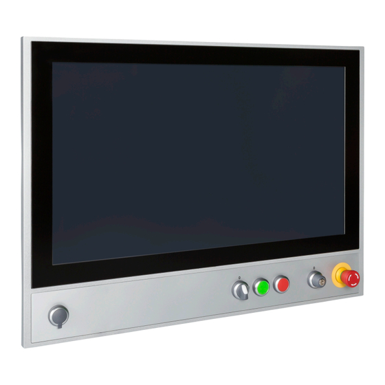
RFID interface (see "Expansion units" on page 127). Legend Front USB RFID interface (5ACCKP03.xxxx-000 and 5ACCKP05.xxxx-000) Selector switches (5ACCKP01.xxxx-000 and 5ACCKP03.xxxx-000) Green pushbutton Blue pushbuttons (5ACCKP04.xxxx-000 and 5ACCKP05.xxxx-000) Red pushbutton Key switch Emergency stop Automation Panel 5000 User's manual V2.11... -
Page 63: Button/Switching Elements
The following graphic show the positions of the buttons and LEDs in the matrix. (Operating element without LED (Control element with LED e.g. key switch) e.g. pushbutton) Hardware number of LED Hardware number of the respective operating element Automation Panel 5000 User's manual V2.11... -
Page 64: Usb Interface
Due to the general PC specification, this interface must be handled with the utmost care with regard to EMC, cable routing, etc. Front USB The front USB interface is available to the user for service purposes. For a more detailed description, see "USB interface" on page 130. Automation Panel 5000 User's manual V2.11... -
Page 65: Button/Switch Interface
Drivers, software tools and documentation for approved operating systems are available for download in the Down- loads section of the B&R website (www.br-automation.com). The software packages for the TWN4 MultiTech Nano must be used. Automation Panel 5000 User's manual V2.11... -
Page 66: Individual Components
XGA, 1024 x 768 pixels Contrast 700:1 Viewing angles Horizontal Direction R = 80° / Direction L = 80° Vertical Direction U = 70° / Direction D = 70° Table 4: 5AP5120.1505-000 - Technical data Automation Panel 5000 User's manual V2.11... - Page 67 299 mm Weight 5200 g Table 4: 5AP5120.1505-000 - Technical data At 25°C ambient temperature. Reducing the brightness by 50% can increase the half-brightness time by approximately 50%. 4.2.1.1.4 Dimensions Figure 6: 5AP5120.1505-000 - Dimensions Automation Panel 5000 User's manual V2.11...
- Page 68 RH [%] T [°C] -50 -40 -30 -20 -10 Figure 7: 5AP5120.1505-000 - Temperature/Humidity diagram Diagram legend Operation T [°C] Temperature in °C Storage and transport RH [%] Relative humidity (RH) in percent and non-condensing Automation Panel 5000 User's manual V2.11...
-
Page 69: 5Ap5120.1906-000
Direction R = 85° / Direction L = 85° Vertical Direction U = 85° / Direction D = 85° Backlight Type Brightness (dimmable) Typ. 35 to 350 cd/m² Half-brightness time 70,000 h Table 6: 5AP5120.1906-000 - Technical data Automation Panel 5000 User's manual V2.11... - Page 70 Weight 7300 g Table 6: 5AP5120.1906-000 - Technical data At 25°C ambient temperature. Reducing the brightness by 50% can increase the half-brightness time by approximately 50%. 4.2.1.2.4 Dimensions 461.2 Figure 8: 5AP5120.1906-000 - Dimensions Automation Panel 5000 User's manual V2.11...
- Page 71 RH [%] T [°C] -50 -40 -30 -20 -10 Figure 9: 5AP5120.1906-000 - Temperature/Humidity diagram Diagram legend Operation T [°C] Temperature in °C Storage and transport RH [%] Relative humidity (RH) in percent and non-condensing Automation Panel 5000 User's manual V2.11...
-
Page 72: 5Ap5130.156B-000
Direction R = 85° / Direction L = 85° Vertical Direction U = 85° / Direction D = 85° Backlight Type Brightness (dimmable) Typ. 40 to 400 cd/m² Half-brightness time 70,000 h Table 8: 5AP5130.156B-000 - Technical data Automation Panel 5000 User's manual V2.11... - Page 73 RH [%] T [°C] -50 -40 -30 -20 -10 Figure 11: 5AP5130.156B-000 - Temperature/Humidity diagram Diagram legend Operation T [°C] Temperature in °C Storage and transport RH [%] Relative humidity (RH) in percent and non-condensing Automation Panel 5000 User's manual V2.11...
-
Page 74: 5Ap5130.156C-000
Direction R = 85° / Direction L = 85° Vertical Direction U = 85° / Direction D = 85° Backlight Type Brightness (dimmable) Typ. 40 to 400 cd/m² Half-brightness time 70,000 h Table 10: 5AP5130.156C-000 - Technical data Automation Panel 5000 User's manual V2.11... - Page 75 RH [%] T [°C] -50 -40 -30 -20 -10 Figure 13: 5AP5130.156C-000 - Temperature/Humidity diagram Diagram legend Operation T [°C] Temperature in °C Storage and transport RH [%] Relative humidity (RH) in percent and non-condensing Automation Panel 5000 User's manual V2.11...
-
Page 76: 5Ap5130.185B-000
Direction R = 85° / Direction L = 85° Vertical Direction U = 80° / Direction D = 80° Backlight Type Brightness (dimmable) Typ. 15 to 300 cd/m² Half-brightness time 50,000 h Table 12: 5AP5130.185B-000 - Technical data Automation Panel 5000 User's manual V2.11... - Page 77 RH [%] T [°C] -50 -40 -30 -20 -10 Figure 15: 5AP5130.185B-000 - Temperature/Humidity diagram Diagram legend Operation T [°C] Temperature in °C Storage and transport RH [%] Relative humidity (RH) in percent and non-condensing Automation Panel 5000 User's manual V2.11...
-
Page 78: 5Ap5130.185C-000
Direction R = 85° / Direction L = 85° Vertical Direction U = 85° / Direction D = 85° Backlight Type Brightness (dimmable) Typ. 40 to 400 cd/m² Half-brightness time 50,000 h Table 14: 5AP5130.185C-000 - Technical data Automation Panel 5000 User's manual V2.11... - Page 79 RH [%] T [°C] -50 -40 -30 -20 -10 Figure 17: 5AP5130.185C-000 - Temperature/Humidity diagram Diagram legend Operation T [°C] Temperature in °C Storage and transport RH [%] Relative humidity (RH) in percent and non-condensing Automation Panel 5000 User's manual V2.11...
-
Page 80: 5Ap5130.215C-000
Direction R = 89° / Direction L = 89° Vertical Direction U = 89° / Direction D = 89° Backlight Type Brightness (dimmable) Typ. 12.5 to 250 cd/m² Half-brightness time 30,000 h Table 16: 5AP5130.215C-000 - Technical data Automation Panel 5000 User's manual V2.11... - Page 81 RH [%] T [°C] -50 -40 -30 -20 -10 Figure 19: 5AP5130.215C-000 - Temperature/Humidity diagram Diagram legend Operation T [°C] Temperature in °C Storage and transport RH [%] Relative humidity (RH) in percent and non-condensing Automation Panel 5000 User's manual V2.11...
-
Page 82: 5Ap5130.240C-000
Direction R = 89° / Direction L = 89° Vertical Direction U = 89° / Direction D = 89° Backlight Type Brightness (dimmable) Typ. 30 to 300 cd/m² Half-brightness time 50,000 h Table 18: 5AP5130.240C-000 - Technical data Automation Panel 5000 User's manual V2.11... - Page 83 At 25°C ambient temperature. Reducing the brightness by 50% can increase the half-brightness time by approximately 50%. 4.2.1.8.4 Dimensions 617.5 Figure 20: 5AP5130.240C-000 - Dimensions 4.2.1.8.5 Temperature/Humidity diagram RH [%] T [°C] -50 -40 -30 -20 -10 Figure 21: 5AP5130.240C-000 - Temperature/Humidity diagram Automation Panel 5000 User's manual V2.11...
- Page 84 Technical data Diagram legend Operation T [°C] Temperature in °C Storage and transport RH [%] Relative humidity (RH) in percent and non-condensing Automation Panel 5000 User's manual V2.11...
-
Page 85: 5Ap5230.156B-000
Model number 5AP5230.156B-000 General information B&R ID code 0xE9F5 Certifications cULus E115267 Industrial control equipment Table 20: 5AP5230.156B-000 - Technical data Automation Panel 5000 User's manual V2.11... - Page 86 349 mm Weight 6400 g Table 20: 5AP5230.156B-000 - Technical data At 25°C ambient temperature. Reducing the brightness by 50% can increase the half-brightness time by approximately 50%. 4.2.1.9.4 Dimensions Figure 22: 5AP5230.156B-000 - Dimensions Automation Panel 5000 User's manual V2.11...
- Page 87 RH [%] T [°C] -50 -40 -30 -20 -10 Figure 23: 5AP230.156B-000 - Temperature/Humidity diagram Diagram legend Operation T [°C] Temperature in °C Storage and transport RH [%] Relative humidity (RH) in percent and non-condensing Automation Panel 5000 User's manual V2.11...
-
Page 88: 5Ap5230.156C-000
Model number 5AP5230.156C-000 General information B&R ID code 0xF24B Certifications cULus E115267 Industrial control equipment Table 22: 5AP5230.156C-000 - Technical data Automation Panel 5000 User's manual V2.11... - Page 89 349 mm Weight 6400 g Table 22: 5AP5230.156C-000 - Technical data At 25°C ambient temperature. Reducing the brightness by 50% can increase the half-brightness time by approximately 50%. 4.2.1.10.4 Dimensions Figure 24: 5AP5230.156C-000 - Dimensions Automation Panel 5000 User's manual V2.11...
- Page 90 RH [%] T [°C] -50 -40 -30 -20 -10 Figure 25: 5AP5230.156C-000 - Temperature/Humidity diagram Diagram legend Operation T [°C] Temperature in °C Storage and transport RH [%] Relative humidity (RH) in percent and non-condensing Automation Panel 5000 User's manual V2.11...
-
Page 91: 5Ap5230.185B-000
The following specified characteristic data, features and limit values are only valid for these individual components and may differ from those of the complete system. The data specified for the complete system applies to the complete system in which this individual component is used, for example. Automation Panel 5000 User's manual V2.11... - Page 92 385.5 mm Weight 8300 g Table 24: 5AP5230.185B-000 - Technical data At 25°C ambient temperature. Reducing the brightness by 50% can increase the half-brightness time by approximately 50%. 4.2.1.11.4 Dimensions Figure 26: 5AP5230.185B-000 - Dimensions Automation Panel 5000 User's manual V2.11...
- Page 93 RH [%] T [°C] -50 -40 -30 -20 -10 Figure 27: 5AP5230.185B-000 - Temperature/Humidity diagram Diagram legend Operation T [°C] Temperature in °C Storage and transport RH [%] Relative humidity (RH) in percent and non-condensing Automation Panel 5000 User's manual V2.11...
-
Page 94: 5Ap5230.185C-000
The following specified characteristic data, features and limit values are only valid for these individual components and may differ from those of the complete system. The data specified for the complete system applies to the complete system in which this individual component is used, for example. Automation Panel 5000 User's manual V2.11... - Page 95 Height 385.5 mm Weight 8300 g Table 26: 5AP5230.185C-000 - Technical data At 25°C ambient temperature. Reducing the brightness by 50% can increase the half-brightness time by approximately 50%. 4.2.1.12.4 Dimensions Figure 28: 5AP5230.185C-000 Automation Panel 5000 User's manual V2.11...
- Page 96 RH [%] T [°C] -50 -40 -30 -20 -10 Figure 29: 5AP5230.185C-000 - Temperature/Humidity diagram Diagram legend Operation T [°C] Temperature in °C Storage and transport RH [%] Relative humidity (RH) in percent and non-condensing Automation Panel 5000 User's manual V2.11...
-
Page 97: 5Ap5230.215C-000
The following specified characteristic data, features and limit values are only valid for these individual components and may differ from those of the complete system. The data specified for the complete system applies to the complete system in which this individual component is used, for example. Automation Panel 5000 User's manual V2.11... - Page 98 Weight 8900 g Table 28: 5AP5230.215C-000 - Technical data At 25°C ambient temperature. Reducing the brightness by 50% can increase the half-brightness time by approximately 50%. 4.2.1.13.4 Dimensions 560.5 Figure 30: 5AP5230.215C-000 - Dimensions Automation Panel 5000 User's manual V2.11...
- Page 99 RH [%] T [°C] -50 -40 -30 -20 -10 Figure 31: 5AP5230.215C-000 - Temperature/Humidity diagram Diagram legend Operation T [°C] Temperature in °C Storage and transport RH [%] Relative humidity (RH) in percent and non-condensing Automation Panel 5000 User's manual V2.11...
-
Page 100: 5Ap5230.215I-000
Model number 5AP5230.215I-000 General information B&R ID code 0xE9F8 Certifications cULus E115267 Industrial control equipment Display Type TFT color Table 30: 5AP5230.215I-000 - Technical data Automation Panel 5000 User's manual V2.11... - Page 101 632 mm Weight 5400 g Table 30: 5AP5230.215I-000 - Technical data At 25°C ambient temperature. Reducing the brightness by 50% can increase the half-brightness time by approximately 50%. 4.2.1.14.4 Dimensions Figure 32: 5AP5230.215I-000 - Dimensions Automation Panel 5000 User's manual V2.11...
- Page 102 RH [%] T [°C] -50 -40 -30 -20 -10 Figure 33: 5AP5230.215I-000 - Temperature/Humidity diagram Diagram legend Operation T [°C] Temperature in °C Storage and transport RH [%] Relative humidity (RH) in percent and non-condensing Automation Panel 5000 User's manual V2.11...
-
Page 103: 5Ap5230.240C-000
The following specified characteristic data, features and limit values are only valid for these individual components and may differ from those of the complete system. The data specified for the complete system applies to the complete system in which this individual component is used, for example. Automation Panel 5000 User's manual V2.11... - Page 104 Weight 10300 g Table 32: 5AP5230.240C-000 - Technical data At 25°C ambient temperature. Reducing the brightness by 50% can increase the half-brightness time by approximately 50%. 4.2.1.15.4 Dimensions 617.5 Figure 34: 5AP5230.240C-000 - Dimensions Automation Panel 5000 User's manual V2.11...
- Page 105 RH [%] T [°C] -50 -40 -30 -20 -10 Figure 35: 5AP5230.240C-000 - Temperature/Humidity diagram Diagram legend Operation T [°C] Temperature in °C Storage and transport RH [%] Relative humidity (RH) in percent and non-condensing Automation Panel 5000 User's manual V2.11...
-
Page 106: Link Modules
Short description Figure Link modules 5DLSD4.1001-00 Automation Panel link module - SDL4 receiver - For Automation Panel 923/933/1000 - For Automation Panel 5000 Required accessories Accessories 0TB103.9 Connector 24 VDC - 3-pin, female - Screw clamp terminal block 3.31 mm²... - Page 107 Width 190 mm Height 110 mm Depth 23.6 mm Weight 525 g Table 34: 5DLSD4.1001-00 - Technical data EN 60950 requirements must be observed; see section "+24 VDC power supply" of the data sheet. Automation Panel 5000 User's manual V2.11...
-
Page 108: 5Dlsd3.1001-00
Short description Figure Link modules 5DLSD3.1001-00 Automation Panel link module - SDL3 receiver - For Automation Panel 923/933/1000 - For Automation Panel 5000 Required accessories Accessories 0TB103.9 Connector 24 VDC - 3-pin, female - Screw clamp terminal block 3.31 mm²... - Page 109 Yes, but applies only if all components installed in the complete system have this certification and the complete system bears the corresponding mark. EN 60950 requirements must be observed; see section "+24 VDC power supply" of the user's manual. Automation Panel 5000 User's manual V2.11...
-
Page 110: 5Dlsdl.1001-00
Short description Figure Link modules 5DLSDL.1001-00 Automation Panel link module - SDL/DVI receiver - For Automa- tion Panel 923/933/1000 - For Automation Panel 5000 Required accessories Accessories 0TB103.9 Connector 24 VDC - 3-pin, female - Screw clamp terminal block 3.31 mm²... - Page 111 Max. USB 1.1 is possible in "SDL operation without USB cable". For the 2 USB type A female connectors. EN 60950 requirements must be observed; see section "+24 VDC power supply" of the user's manual. Automation Panel 5000 User's manual V2.11...
-
Page 112: Mounting Units
Swing arm (with flange) Dimensions Width 280 mm Height 259 mm Depth 96 mm Weight 2500 g Table 40: 5ACCMA00.0000-000 - Technical data Only with proper installation on the panel and proper installation on the swing arm. Automation Panel 5000 User's manual V2.11... -
Page 113: 5Accma00.0001-000
Swing arm (with flange) Dimensions Width 280 mm Height 259 mm Depth 96 mm Weight 2500 g Table 42: 5ACCMA00.0001-000 - Technical data Only with proper installation on the panel and proper installation on the swing arm. Automation Panel 5000 User's manual V2.11... - Page 114 In SDL3 operation: Low speed (1.5 Mbit/s), full speed (12 Mbit/s) to high speed (30 Mbit/s) In SDL4 operation: Low speed (1.5 Mbit/s), full speed (12 Mbit/s) to high speed (150 Mbit/s) The USB interface is protected by a maintenance-free "USB current-limiting switch" (max. 0.5 A). Automation Panel 5000 User's manual V2.11...
-
Page 115: 5Accma00.0002-000
Swing arm (with flange) Dimensions Width 280 mm Height 259 mm Depth 96 mm Weight 2500 g Table 44: 5ACCMA00.0002-000 - Technical data Only with proper installation on the panel and proper installation on the swing arm. Automation Panel 5000 User's manual V2.11... - Page 116 In SDL3 operation: Low speed (1.5 Mbit/s), full speed (12 Mbit/s) to high speed (30 Mbit/s) In SDL4 operation: Low speed (1.5 Mbit/s), full speed (12 Mbit/s) to high speed (150 Mbit/s) The USB interface is protected by a maintenance-free "USB current-limiting switch" (max. 0.5 A). Automation Panel 5000 User's manual V2.11...
-
Page 117: 5Accma01.0100-000
White aluminum (similar to RAL 9006) Installation VESA Dimensions Width 270 mm Height 189 mm Depth 51 mm Weight 900 g Table 46: 5ACCMA01.0100-000 - Technical data Only with proper installation on the panel. Automation Panel 5000 User's manual V2.11... -
Page 118: 5Accma00.0100-000
Degree of protection per EN 60529 IP54 Degree of protection per UL 50 Type 1 Mechanical properties Housing Material Aluminum, coated Coating White aluminum (similar to RAL 9006) Installation VESA Table 48: 5ACCMA00.0100-000 - Technical data Automation Panel 5000 User's manual V2.11... - Page 119 Technical data Model number 5ACCMA00.0100-000 Dimensions Width 280 mm Length 259 mm Height 60.25 mm Weight 2.6 kg Table 48: 5ACCMA00.0100-000 - Technical data Only with proper installation on the panel. Automation Panel 5000 User's manual V2.11...
-
Page 120: 5Accma00.0101-000
Max. 500 mA Operating conditions Pollution degree per EN 61131-2 Pollution degree 2 Degree of protection per EN 60529 IP54 Degree of protection per UL 50 Type 1 Table 50: 5ACCMA00.0101-000 - Technical data Automation Panel 5000 User's manual V2.11... - Page 121 In SDL3 operation: Low speed (1.5 Mbit/s), full speed (12 Mbit/s) to high speed (30 Mbit/s) In SDL4 operation: Low speed (1.5 Mbit/s), full speed (12 Mbit/s) to high speed (150 Mbit/s) The USB interface is protected by a maintenance-free "USB current-limiting switch" (max. 0.5 A). Automation Panel 5000 User's manual V2.11...
-
Page 122: Flange
Pollution degree 2 Mechanical properties Material Aluminum (similar to RAL 9006), coated Dimensions Height 55 mm Diameter 75 mm (outer diameter) 48.5 mm (inner diameter) Weight 530 g Table 52: 5ACCFL00.0000-000 - Technical data Automation Panel 5000 User's manual V2.11... - Page 123 Technical data 4.2.4.1.4 Dimensions ø75 ø48.5 Figure 36: 5ACCFL00.0000-000 - dimensions Automation Panel 5000 User's manual V2.11...
-
Page 124: 5Accfl00.0100-000
Model number 5ACCFL00.0100-000 General information Certifications Product family certification cULus E115267 Industrial control equipment Table 54: 5ACCFL00.0100-000 - Technical data Automation Panel 5000 User's manual V2.11... - Page 125 The swivel-tilt flange is only permitted to be used in conjunction with devices supplied with a SELV/ PELV power supply or with safety extra-low voltage (SELV) per EN 60950. 4.2.4.2.4 Dimensions Figure 37: 5ACCFL00.0100-000 - Dimensions Automation Panel 5000 User's manual V2.11...
-
Page 126: 5Accfl00.0200-000
Aluminum, coated Dimensions Height 8.5 mm Diameter 90 mm (outer diameter) 42 mm (inner diameter) Weight 93 g Table 56: 5ACCFL00.0200-000 - Technical data 4.2.4.3.4 Dimensions 4x 7 ° Figure 38: 5ACCFL00.0200-000 - dimensions Automation Panel 5000 User's manual V2.11... -
Page 127: Expansion Units
Model number 5ACCKP00.156B-000 5ACCKP00.185B-000 5ACCKP00.215C-000 5ACCKP00.215I-000 5ACCKP00.240C-000 General information Certifications Product family certification cULus E115267 Industrial control equipment Table 58: 5ACCKP00.156B-000, 5ACCKP00.185B-000, 5ACCK- P00.215C-000, 5ACCKP00.215I-000, 5ACCKP00.240C-000 - Technical data Automation Panel 5000 User's manual V2.11... - Page 128 Operating conditions Pollution degree per EN 61131-2 Pollution degree 2 Mechanical properties Material Steel sheet Weight 600 g 800 g 500 g 900 g Table 58: 5ACCKP00.156B-000, 5ACCKP00.185B-000, 5ACCK- P00.215C-000, 5ACCKP00.215I-000, 5ACCKP00.240C-000 - Technical data Automation Panel 5000 User's manual V2.11...
-
Page 129: 5Acckp01.Xxxx-000
Low speed (1.5 Mbit/s), full speed (12 Mbit/s) to high speed (480 Mbit/s) Current-carrying capacity 500 mA Features Pushbuttons Quantity 2 (green, red) Type RAFIX 22 FS+, 1.30.270.021/2500 (green), 1.30.270.021/2300 (red) Contact element Momentary Table 60: 5ACCKP01.156B-000, 5ACCKP01.185B-000, 5ACCK- P01.215C-000, 5ACCKP01.215I-000, 5ACCKP01.240C-000 - Technical data Automation Panel 5000 User's manual V2.11... - Page 130 In SDL3 operation: Low speed (1.5 Mbit/s), full speed (12 Mbit/s) to high speed (30 Mbit/s) In SDL4 operation: Low speed (1.5 Mbit/s), full speed (12 Mbit/s) to high speed (150 Mbit/s) The USB interface is protected by a maintenance-free "USB current-limiting switch" (max. 0.5 A). Automation Panel 5000 User's manual V2.11...
-
Page 131: 5Acckp03.Xxxx-000
Read/Write range in air Up to 2 cm (depends on transponder) Features Pushbuttons Quantity 2 (green, red) Type RAFIX 22 FS+, 1.30.270.021/2500 (green), 1.30.270.021/2300 (red) Contact element Momentary Table 62: 5ACCKP03.185B-000, 5ACCKP03.215C-000, 5ACCKP03.240C-000 - Technical data Automation Panel 5000 User's manual V2.11... - Page 132 100 m SDL4 operation USB 2.0 100 m The max. cable length of 25 m depends on the resolution. For exact specifications, see table "Title" on page 51 " in the AP5000 user's manual. Automation Panel 5000 User's manual V2.11...
- Page 133 In SDL3 operation: Low speed (1.5 Mbit/s), full speed (12 Mbit/s) to high speed (30 Mbit/s) In SDL4 operation: Low speed (1.5 Mbit/s), full speed (12 Mbit/s) to high speed (150 Mbit/s) The USB interface is protected by a maintenance-free "USB current-limiting switch" (max. 0.5 A). Automation Panel 5000 User's manual V2.11...
-
Page 134: 5Acckp04.Xxxx-000
RAFIX 22 FS+, 1.30.270.021/2600 (blue), 1.30.270.021/2500 (green), 1.30.270.021/2300 (red) Contact element Momentary Key switch Quantity Type RAFIX 22 FS 1.30.255.222/0000 Contact element Maintained Table 64: 5ACCKP04.156B-000, 5ACCKP04.185B-000, 5ACCK- P04.215C-000, 5ACCKP04.215I-000, 5ACCKP04.240C-000 - Technical data Automation Panel 5000 User's manual V2.11... - Page 135 In SDL3 operation: Low speed (1.5 Mbit/s), full speed (12 Mbit/s) to high speed (30 Mbit/s) In SDL4 operation: Low speed (1.5 Mbit/s), full speed (12 Mbit/s) to high speed (150 Mbit/s) The USB interface is protected by a maintenance-free "USB current-limiting switch" (max. 0.5 A). Automation Panel 5000 User's manual V2.11...
-
Page 136: 5Acckp05.Xxxx-000
Up to 2 cm (depends on transponder) Features Pushbuttons Quantity 3 (blue, green, red) Type RAFIX 22 FS+, 1.30.270.021/2600 (blue), 1.30.270.021/2500 (green), 1.30.270.021/2300 (red) Contact element Momentary Table 66: 5ACCKP05.185B-000, 5ACCKP05.215C-000, 5ACCKP05.240C-000 - Technical data Automation Panel 5000 User's manual V2.11... - Page 137 100 m SDL4 operation USB 2.0 100 m The max. cable length of 25 m depends on the resolution. For exact specifications, see table "Title" on page 51 " in the AP5000 user's manual. Automation Panel 5000 User's manual V2.11...
- Page 138 In SDL3 operation: Low speed (1.5 Mbit/s), full speed (12 Mbit/s) to high speed (30 Mbit/s) In SDL4 operation: Low speed (1.5 Mbit/s), full speed (12 Mbit/s) to high speed (150 Mbit/s) The USB interface is protected by a maintenance-free "USB current-limiting switch" (max. 0.5 A). Automation Panel 5000 User's manual V2.11...
-
Page 139: 5Acckpsx.xxxx-Xxx
Technical data 4.2.5.6 5ACCKPSx.xxxx-xxx Safe variants of expansion units are also available. For details, see www.br-automation.com. Automation Panel 5000 User's manual V2.11... -
Page 140: Handles
Product family certification cULus E115267 Industrial control equipment Operating conditions Pollution degree per EN 61131-2 Pollution degree 2 Mechanical properties Material Aluminum, coated Table 69: 5ACCHD01.156B-000, 5ACCHD01.185B-000, 5AC- CHD01.215C-000, 5ACCHD01.215I-000, 5ACCHD01.240C-000 - Technical data Automation Panel 5000 User's manual V2.11... - Page 141 1000 g 800 g Table 69: 5ACCHD01.156B-000, 5ACCHD01.185B-000, 5AC- CHD01.215C-000, 5ACCHD01.215I-000, 5ACCHD01.240C-000 - Technical data 4.2.6.1.4 Content of delivery • 2x handles • 4x Torx screws (T20) Figure 39: 5ACCHD0x.xxxx-000 - Content of delivery Automation Panel 5000 User's manual V2.11...
-
Page 142: Installation And Wiring
• This device is only approved for use in closed rooms and not permitted to be exposed to direct sunlight. • The climatic and ambient conditions must be taken into account, see "Environmental properties" on page Automation Panel 5000 User's manual V2.11... - Page 143 Damaged packaging indicates that the device has been severely affected by environmental influences and may have been damaged. This can result in malfunctions of the device, machine or system. Automation Panel 5000 User's manual V2.11...
-
Page 144: Automation Panel 5000 - Installation
Installation and wiring 5.2 Automation Panel 5000 - Installation The Automation Panel 5000 is installed on the swing arm system using a rotary flange. 5.2.1 Installation with flange Information: Before installing the Automation Panel on a swing arm system, it must be checked as to whether the sealing ring is installed on the flange. - Page 145 5 Nm). The screw in the locking lever is not permitted to be tightened. Fixing must be carried out exclu- sively with the locking lever. 3x M6 headless screws ! 5 Nm Locking lever Automation Panel 5000 User's manual V2.11...
-
Page 146: Removing The Mounting Unit Cover
4. Replace the mounting unit cover with the 4 Torx screws removed earlier (tightening torque of the M5x12 screws: 2.5 Nm, for the M5x40 screws: 4.0 Nm). The cover must be installed correctly to ensure IP65 pro- tection. Automation Panel 5000 User's manual V2.11... -
Page 147: Removing The Link Module
5. Pull firmly and evenly to remove the link module. Figure 42: Removing the link module 6. The link module can now be replaced by following these steps in reverse order. The max. tightening torque of the Torx screws (T10) is 0.5 Nm. Automation Panel 5000 User's manual V2.11... -
Page 148: Installing Accessories
4. Remove the top and bottom Torx screws (T20) on the side of the panel. 5. Insert the provided Torx screws (T20) through the handle and tighten with max. tightening torque of 1.24 Nm. Automation Panel 5000 User's manual V2.11... -
Page 149: Installing The 5Accfl00.0000-000 Rotary Flange
7. Place the rotary flange in the intended opening on the mounting unit with the locking lever pointing towards the mounting unit. Fasten it to the mounting unit using the 4 provided Torx screws (T30) with a tightening torque of 7.2 Nm. Automation Panel 5000 User's manual V2.11... -
Page 150: Installing The 5Accfl00.0100-000 Swivel-Tilt Flange
6. Check whether the sealing ring is inserted in the swivel-tilt flange. If the sealing ring is not installed in the swivel-tilt flange, it must be inserted into the sealing recess. 7. Pass the cables that should be connected through the swing arm (in case this is also installed) and the swivel-tilt flange. Automation Panel 5000 User's manual V2.11... - Page 151 It is important to ensure that the cables are not pinched! Warning! The following tightening torques must be observed: • Tilt flange locking lever: 7 Nm • Locking lever rotary flange: 5 Nm Failure to do so can result in damage to property. Automation Panel 5000 User's manual V2.11...
- Page 152 Failure to follow these instructions can result in damage to property. Warning! The M5x65 screws are equipped with a special screw locking mechanism and only designed to be used once. New screws must be used if removing and reinstalling. Automation Panel 5000 User's manual V2.11...
- Page 153 Installation and wiring 6. Pull evenly to remove the mounting unit from the panel. Automation Panel 5000 User's manual V2.11...
- Page 154 • It is important to ensure that the gasket is completely inserted into the installation notch. • The housing components must be secured using the specified tightening torque. Failure to follow these instructions can result in damage to property. Automation Panel 5000 User's manual V2.11...
- Page 155 New screws must be used if removing and reinstalling. 6. Install the cover for the mounting unit by performing the steps provided in section "Removing the mounting unit cover" on page 146 in reverse order. Automation Panel 5000 User's manual V2.11...
- Page 156 4. Remove the 4 Torx screws (T25: 4x M5x10) and 2 metal pieces (designed for the cable strain relief clip) used to install the mounting unit on the panel. 5. Pull evenly to remove the mounting unit from the panel. Automation Panel 5000 User's manual V2.11...
- Page 157 (designed for the cable strain relief clip). The tightening torque for each is 3.5 Nm. Follow the order shown in the following figure. 5. 4 Torx screws (T20: 4x M4x10) and 6 cable ties are supplied for fastening the Automation Panel to a VESA bracket. Observer the installation notes from the manufacturer. Automation Panel 5000 User's manual V2.11...
- Page 158 • The Automation Panel must no longer be installed on the VESA bracket. 1. To uninstall the IP54 VESA mounting unit, perform the installation in reverse order (see "Installing the IP54 VESA mounting unit" on page 159). Automation Panel 5000 User's manual V2.11...
- Page 159 Failure to follow this instruction can result in damage to property. 6. If the mounting unit is used in conjunction with a PPC2200, the heat pipe including heat pipe cover must also be installed. The following figure symbolically displays the heat pipe installation. Automation Panel 5000 User's manual V2.11...
- Page 160 7. Place the mounting unit cover on the frame. 8. Install the cover using the 8 provided Torx screws (T25: 6x M5x20 and T20: 2x M4x12). Tightening torque: 2.5 Nm for M5, 1.24 Nm for M4. Automation Panel 5000 User's manual V2.11...
- Page 161 • The gasket must be inspected before installation or reinstallation and at regular intervals according to the requirements of the operating environment. • Replace the entire device if inspection reveals visible scratches, cracks, dirt deposits or excessive wear. Automation Panel 5000 User's manual V2.11...
- Page 162 • Avoid contact between the gasket and the corners and edges of the frame. • It is important to ensure that the gasket is completely inserted into the installation notch. • The housing components must be secured using the specified tightening torque. Automation Panel 5000 User's manual V2.11...
- Page 163 It is important to ensure that cables and wires are not pinched. 6. It is possible to lead any wiring or extensions to the outside through an installed flange via the cable ducts in the panel. Automation Panel 5000 User's manual V2.11...
- Page 164 • Avoid contact between the gasket and the corners and edges of the frame. • It is important to ensure that the gasket is completely inserted into the installation notch. • The housing components must be secured using the specified tightening torque. Automation Panel 5000 User's manual V2.11...
- Page 165 10.Cut the panel overlay so that it is flush with the edge of the steel plate. 11. Operating elements can now be installed on the expansion cover. For more information about operating and switching elements, see section "Features" on page 202. Automation Panel 5000 User's manual V2.11...
- Page 166 4 large openings of the pushbutton. 2. If required, the colored lens can be removed using a sharp object. Refer to the manufacturer guidelines for additional information about in- stalling operating elements. Automation Panel 5000 User's manual V2.11...
- Page 167 ➁ as shown in the figure below. Close the terminal contact by removing the screwdriver. It is important to pay attention to the label on the spring clamp terminal ④. 24 VDC 0 VDC Automation Panel 5000 User's manual V2.11...
- Page 168 The functional ground on the B&R device is marked with the following symbol: Legend Power supply connection +24 VDC pin 2 Central grounding point Ground connection At least 1.5 mm² At least 2.5 mm² Automation Panel 5000 User's manual V2.11...
- Page 169 Locating screws 5.7.1 Wiring with SDL cables It is possible to use 5CASDL.0xxx-00 SDL cables, 5CASDL.0xxx-01 SDL cables with 45° connector and 5CASDL.0xxx-03 SDL flex cables for the Automation Panel 5000 with SDL receiver. Automation Panel 5000 User's manual V2.11...
- Page 170 • An Automation PC or Panel PC is connected (via DVI, SDL, SDL3 or SDL4). 6.2.2 Switching on the Automation Panel Procedure 1. Connect the power supply and switch it on. 2. The device is operating. Automation Panel 5000 User's manual V2.11...
- Page 171 (www.br-automation.com). 6.3.1.8 Windows Embedded Standard 2009 After starting Windows Embedded Standard 2009 on the Panel PC or Power Panel for the first time (first boot agent), the corresponding touch screen driver is installed automatically. Automation Panel 5000 User's manual V2.11...
- Page 172 6.3.2.6 Windows Embedded Standard 7 Premium Microsoft multi-touch drivers are installed on the device during installation of Windows Embedded Standard 7 Premium. After successful installation of Windows Embedded Standard 7 Premium, the device is immediately ready for operation. Automation Panel 5000 User's manual V2.11...
- Page 173 BIOS is used until Windows boots. The value set in BIOS is only applied the first time the Control Center is launched. 6.4.2 Adjusting in DVI operation 1. Use the two brightness controls on the SDL/DVI receiver to set the brightness (for further information, see "SDL/DVI receiver (5DLSDL.1001-00)" on page Automation Panel 5000 User's manual V2.11...
- Page 174 • Windows Embedded Standard 7 Premium • B&R Linux 8 and 9 No guarantee can be given for multi-touch or single-touch operation, compatibility and functionality for operation with other operating systems and/or individual touch screen drivers. Automation Panel 5000 User's manual V2.11...
- Page 175 7.3.2 System requirements The following software versions (or higher) are required to operate Automation Runtime (ARemb and ARwin) with an Automation Panel 5000: • ARemb upgrade AR K4.10 and Automation Studio V4.2.5 Automation Panel 5000 User's manual V2.11...
- Page 176 The ADI driver (also includes the Control Center) and user documentation can be downloaded at no cost from the Downloads section of the B&R website (www.br-automation.com). If a more recent version is available, it can be installed later. Information: The Write filter must be disabled during installation. Automation Panel 5000 User's manual V2.11...
- Page 177 B&R images of embedded operating systems. For a detailed description of how to use ADI functions, see Automation Help. The B&R ADI Development Kit can be downloaded at no cost from the Downloads section of the B&R website (www.br-automation.com). Automation Panel 5000 User's manual V2.11...
- Page 178 B&R images of embedded operating systems. For a detailed description of how to use ADI functions, see Automation Help. The ADI .NET SDK can be downloaded at no cost from the Downloads section of the B&R website (www.br- automation.com). Automation Panel 5000 User's manual V2.11...
- Page 179 For detailed instructions about configuring keys and LEDs and installing the key configuration on the target system, see the help documentation for the Key Editor. The Key Editor and help documentation can be downloaded at no cost from the Downloads section of the B&R website (www.br-automation.com). Automation Panel 5000 User's manual V2.11...
- Page 180 If the KCF Editor is running on the target device and the ADI driver is installed, the following additional features are available: • Panel and key detection • LED test • Download/Upload the configuration Automation Panel 5000 User's manual V2.11...
- Page 181 - For APC810/PPC800 - For APC910/PPC900 - For APC2100/PPC2100 - For APC2200/PPC2200 - For APC3100/ PPC3100 - For APC51x/PP500 - For Automation Panel 800/900 - For Automation Panel 1000/5000 Table 70: 5SWUTI.0001-000 - Order data Automation Panel 5000 User's manual V2.11...
- Page 182 • The cleaning agent is not permitted to be applied directly to the device. Abrasive cleaners, aggressive solvents and chemicals, compressed air or steam cleaners are not permitted to be used. Information: Displays with a touch screen should be cleaned at regular intervals. Automation Panel 5000 User's manual V2.11...
- Page 183 Repairs are therefore only permitted to be carried out by authorized qualified personnel at the manufacturer's premises. To process a repair/complaint, a repair order or complaint must be created via the B&R Material Return Portal on the B&R website (www.br-automation.com). Automation Panel 5000 User's manual V2.11...
- Page 184 The following specified characteristic data, features and limit values are only valid for this accessory and may differ from those of the complete system. The data specified for the complete system applies to the complete system in which this accessory is installed, for example. Automation Panel 5000 User's manual V2.11...
- Page 185 Yes, but applies only if all components installed in the complete system have this certification and are listed on the associated DNV GL certificate for the product family. The cage clamp terminal block cannot be used side by side. The respective limit data of the I/O modules must be taken into account! Automation Panel 5000 User's manual V2.11...
- Page 186 Full speed: Max. 0.9 MB/s High speed: Max. 23 MB/s Endurance SLC flash memory Data retention >10 years Data reliability <1 unrecoverable error per 10 bits read Mating cycles >1500 Table 74: 5MMUSB.2048-01, 5MMUSB.4096-01 - Technical data Automation Panel 5000 User's manual V2.11...
- Page 187 The maximum ambient temperature is typically derated 1°C per 1000 meters starting at 500 m above sea level. 9.3.1.4 Temperature/Humidity diagram RH [%] T [°C] -50 -40 -30 -20 -10 Diagram legend Operation T [°C] Temperature in °C Storage and transport RH [%] Relative humidity (RH) in percent and non-condensing Automation Panel 5000 User's manual V2.11...
- Page 188 Max. 67 mA in sleep mode, max. 122 mA read, max. 141 mA write Ambient conditions Temperature Operation 0 to 70°C Storage -55 to 95°C Transport -55 to 95°C Table 76: 5MMUSB.032G-02 - Technical data Automation Panel 5000 User's manual V2.11...
- Page 189 The maximum ambient temperature is typically derated 1°C per 1000 meters starting at 500 m above sea level. 9.3.2.4 Temperature/Humidity diagram RH [%] T [°C] -50 -40 -30 -20 -10 Diagram legend Operation T [°C] Temperature in °C RH [%] Relative humidity (RH) in percent and non-condensing Storage and transport Automation Panel 5000 User's manual V2.11...
- Page 190 Heat pipe 5ACCHP00.0003-000 is used to improve heat dissipation. It is used only in conjunction with PPC2200 system units and VESA IP54 mounting unit. 9.5.2.2 Order data Model number Short description Figure Heat pipe 5ACCHP00.0003-000 HMI Heatpipe00 PPC2200+AP5000 VESA Table 78: 5ACCHP00.0003-000 - Order data Automation Panel 5000 User's manual V2.11...
- Page 191 Evaluation of human exposure to electromagnetic fields from short-range devices (SRDs) in various applications over the frequency range 0 GHz to 300 GHz - Part 1: Fields produced by devices used for electronic article surveillance, radio frequency identification and similar systems Automation Panel 5000 User's manual V2.11...
- Page 192 Electromagnetic compatibility (EMC) - Part 6-4: Generic standards - Emission stan- dard for industrial environments Information: The declarations of conformity are available on the B&R website under Downloads - Certificates - Declarations of conformity. Automation Panel 5000 User's manual V2.11...
- Page 193 Products with this mark are tested by an accredited test laboratory and certified by the ACMA. The mark is valid for Australia/Oceania and facilitates the certification of your machines and systems in this economic area (based on EU conformity). Automation Panel 5000 User's manual V2.11...
- Page 194 Taiwan: 第十二條: 經型式認證合格之低功率射頻電機,非經許可,公司、商號或使用者 根據NCC低功率電波輻射性 均不得擅自變更頻率、加大功率或變更原設計之特性及功能。 電機管理辦法 規定: 第十四條: 低功率射頻電機之使用不得影響飛航安全及干擾合法通信;經發現有 干擾現象時,應立即停用,並改善至無干擾時方得繼續使用。 前項合法通信, 指依電信法規定作業之無線電通信。 低功率射頻電機須忍受合法通信或工業、 科學及醫療用電波輻射性電機設備之干擾。 此模組於取得認證後將依規定於模組本體標示審驗合格標籤,並要求平台廠商 於平台上標示『內含發射器模組: RFM-2-NF RFM-3-BTW Automation Panel 5000 User's manual V2.11...
- Page 195 Products with RFM-3-BTW and/or RFM-2-NF boards are approved for use in the USA and Canada. The types can be identified by an adhesive label bearing the appropriate marks - identifiable by the information "Contains FCC ID:" and "Contains IC:". Automation Panel 5000 User's manual V2.11...
- Page 196 Electronics recycling Operating and monitoring devices Uninterruptible power supplies Batteries and rechargeable batteries Cables Paper/Cardboard packaging Paper/Cardboard recycling Plastic packaging material Plastic recycling Disposal must be carried out in accordance with applicable legal regulations. Automation Panel 5000 User's manual V2.11...
- Page 197 Used in technical data tables if there is currently no value for specific technical data. The value will be supplied later. MTBF Mean time between failures The expected value of the operating time between two consecutive failures. Automation Panel 5000 User's manual V2.11...
- Page 198 Appendix B Appendix B Viewing angles For viewing angle specifications (R, L, U, D) of the display types, see the technical data of the individual compo- nents. 6 o'clock direction Automation Panel 5000 User's manual V2.11...
- Page 199 All panels are made of a coated aluminum support frame. Single-touch panels • Single-touch panels are manufactured with Autotex panel overlay: Touch screen Panel overlay Multi-touch panels • Multi-touch panels are manufactured with a continuous glass surface. Automation Panel 5000 User's manual V2.11...
- Page 200 • Sidolin • Diesel • Sodium hydroxide < 40% • Skydrol • Acetic acid < 50% • Petroleum The coated aluminum front is not resistant to the following chemicals: • Acetone • Ethyl acetate Automation Panel 5000 User's manual V2.11...
- Page 201 • Lysol • Water • Hydrogen chloride < 6% • Methylbenzene • White wine vinegar • Coca-Cola • Methyl ethyl ketone • Windex Original • Dimethylbenzene • Naphtha • Ethanol • Nitric acid < 70% Automation Panel 5000 User's manual V2.11...
- Page 202 1.30.272.102/2200 Illumination White Contact function Maintained Angle of rotation 1 x 90°, L form Service life (switching cycles) 300,000 B10 value (switching cycles) 400,000 Actuation torque Max. 1.5 Nm Table 82: Selector switch 1.30.272.102/2200 Automation Panel 5000 User's manual V2.11...
- Page 203 AC/DC operating voltage Min. 1 V AC/DC operating voltage Max. 35 V AC/DC operating current Min. 1 mA AC/DC operating current Max. 100 mA Switching capacity Max. 250 mW Table 85: Switching element 1.20.126.005/0000 Automation Panel 5000 User's manual V2.11...
- Page 204 D.9.1.2 Colored lens RAFIX 22 FS+, 5.49.263.062/1000 Colored lens 5.49.263.062/1000 Manufacturer RAFI Example image Type RAFIX 22 FS+ Manufacturer number 5.49.263.062/1000 Quantity Form of lens Flat lens Lens color Colorless Table 88: Colored lens 5.49.263.062/1000 Automation Panel 5000 User's manual V2.11...
- Page 205 B10 value (switching cycles) 1,300,000 Min. AC/DC operating voltage Max. AC/DC operating voltage 35 V Min. AC/DC operating current 1 mA Max. AC/DC operating current 100 mA Max. switching capacity 250 mW Table 93: Switching element 1.20.126.102/9000 Automation Panel 5000 User's manual V2.11...
- Page 206 D.9.2.5 Colored lens RAFIX 22 FS+, 5.49.263.062/1500 Colored lens 5.49.263.062/1500 Manufacturer RAFI Example image Type RAFIX 22 FS+ Manufacturer number 5.49.263.062/1500 Quantity Form of lens Flat lens Lens color Green Table 98: Colored lens 5.49.263.062/1500 Automation Panel 5000 User's manual V2.11...
- Page 207 RAFIX 22 FS+ emergency stop button "Plus 1" Manufacturer number 1.30.273.512/0300 Quantity Contact function Maintained Resetting By rotating to the right Service life (switching cycles) 50,000 B10 value (switching cycles) 65,000 Table 101: Emergency stop 1.30.273.512/0300 Automation Panel 5000 User's manual V2.11...
- Page 208 D.9.4.2 Switching element RAFIX 22 FS, 1.20.126.105/9000 Switching element 1.20.126.105/9000 Manufacturer RAFI Type RAFIX 22 FS Manufacturer number 1.20.126.105/9000 Example image Quantity Contact system Self-cleaning bridge contact Contacts 2 normally open contacts Table 104: Switching element 1.20.126.105/9000 Automation Panel 5000 User's manual V2.11...
- Page 209 Service life (switching cycles) 1,000,000 Min. AC/DC operating voltage Max. AC/DC operating voltage 35 V Min. AC/DC operating current 1 mA Max. AC/DC operating current 100 mA Max. switching capacity 250 mW Table 104: Switching element 1.20.126.105/9000 Automation Panel 5000 User's manual V2.11...
- Page 210 1,000,000 at 10 mA / 24 VDC Min. AC/DC operating voltage Max. AC/DC operating voltage 42 V Min. AC/DC operating current 1 mA Max. AC/DC operating current 100 mA Max. switching capacity 250 mW Table 106: Switching element 1.20.126.103/9000 Automation Panel 5000 User's manual V2.11...
- Page 211 B10 value (switching cycles) 1,300,000 Min. AC/DC operating voltage Max. AC/DC operating voltage 35 V Min. AC/DC operating current 1 mA Max. AC/DC operating current 100 mA Max. switching capacity 250 mW Table 108: Switching element 1.20.126.102/9000 Automation Panel 5000 User's manual V2.11...
- Page 212 In SDL3 operation: Low speed (1.5 Mbit/s), full speed (12 Mbit/s) to high speed (30 Mbit/s) In SDL4 operation: Low speed (1.5 Mbit/s), full speed (12 Mbit/s) to high speed (150 Mbit/s) The USB interface is protected by a maintenance-free "USB current-limiting switch" (max. 500 mA). Automation Panel 5000 User's manual V2.11...
- Page 213 -50 -40 -30 -20 -10 Figure 44: 5-wire AMT touch screen - Temperature/Humidity diagram Diagram legend Operation T [°C] Temperature in °C Storage and transport RH [%] Relative humidity (RH) in percent and non-condensing Automation Panel 5000 User's manual V2.11...
- Page 214 Table 111: Touchscreen 3M - Technical data E.2.2 Temperature/Humidity diagram RH [%] T [°C] -50 -40 -30 -20 -10 Diagram legend Operation T [°C] Temperature in °C Storage and transport RH [%] Relative humidity (RH) in percent and non-condensing Automation Panel 5000 User's manual V2.11...
- Page 215 Publishing information Automation Panel 5000 User's manual V2.11...
- Page 216 Publishing information Publishing information B&R Industrial Automation GmbH B&R Strasse 1 5142 Eggelsberg Austria Telephone: +43 7748 6586-0 Fax: +43 7748 6586-26 office@br-automation.com Automation Panel 5000 User's manual V2.11...
Need help?
Do you have a question about the Automation Panel 5000 and is the answer not in the manual?
Questions and answers