Table of Contents
Advertisement
Power Panel C-Series
User's Manual
Version: 1.00 (October 2014)
Model no.: MAPPC-ENG
All information contained in this manual is current as of its creation/publication. B&R reserves the right to change
the contents of this manual without notice. The information contained herein is believed to be accurate as of
the date of publication; however, Bernecker + Rainer Industrie-Elektronik Ges.m.b.H. makes no warranty, ex-
pressed or implied, with regard to the products or documentation contained within this manual. In addition,
Bernecker + Rainer Industrie-Elektronik Ges.m.b.H. shall not be liable for any incidental or consequential damages
in connection with or arising from the furnishing, performance or use of the product(s) in this documentation. Soft-
ware names, hardware names and trademarks are registered by their respective companies.
1
Advertisement
Table of Contents

Related Manuals for B&R Power Panel C Series


Summary of Contents for B&R Power Panel C Series
- Page 1 Power Panel C-Series User's Manual Version: 1.00 (October 2014) Model no.: MAPPC-ENG All information contained in this manual is current as of its creation/publication. B&R reserves the right to change the contents of this manual without notice. The information contained herein is believed to be accurate as of the date of publication;...
-
Page 2: Table Of Contents
Table of contents Chapter 1 General information................... 4 1 Manual history..............................4 2 Safety guidelines..............................4 2.1 Introduction..............................4 2.2 Intended use..............................4 2.3 Protection against electrostatic discharge....................4 2.3.1 Packaging..............................5 2.3.2 Guidelines for proper ESD handling.......................5 2.4 Transport and storage..........................5 2.5 Installation..............................5 2.6 Operation.............................. - Page 3 Table of contents Chapter 5 Accessories....................85 1 Overview................................85 2 TB102 2-pin power supply connector......................86 2.1 Order data..............................86 2.2 Technical data............................86 3 TB510x 4/6-pin terminal block......................... 87 3.1 Order data..............................87 3.2 Technical data............................87 4 Data storage media............................87 5 Cable accessories............................87 Chapter 6 Maintenance....................
-
Page 4: Chapter 1 General Information
General information • Safety guidelines Chapter 1 • General information Information: B&R keeps the printed version of user's manuals as current as possible. If a newer version of the user's manual is available, it can always be downloaded in electronic form (PDF) from the B&R website www.br-automation.com 1 Manual history Version... -
Page 5: Packaging
General information • Safety guidelines 2.3.1 Packaging • Electrical components with a housing … do not require special ESD packaging, but must be handled properly (see "Electrical components with a housing" on page 5). • Electrical components without a housing …... -
Page 6: Operation
General information • Safety guidelines 2.6 Operation 2.6.1 Protection against touching electrical parts To operate programmable logic controllers, operating/monitoring devices or uninterruptible power supplies, it is necessary for certain parts to carry dangerous voltage levels over 42 VDC. Touching one of these parts can result in a life-threatening electric shock. -
Page 7: Chapter 2 Power Panel C-Series
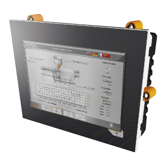
Power Panel C-Series • System features Chapter 2 • Power Panel C-Series 1 System features B&R has added the new Power Panel C-Series to its Power Panel family. The Power Panel C70 achieves cycle times as fast as 1 ms. In addition to POWERLINK, Ethernet, USB and X2X Link connections, the devices are also available with an option board, providing CAN, RS232 and RS485 interfaces. -
Page 8: Power Panel C70
Power Panel C-Series • System features 1.3 Power Panel C70 The Power Panel C70 is an HMI terminal with a built-in PLC. The Intel Atom processor provides enough perfor- mance to allow applications to achieve cycle times down to 1 ms. Automation Runtime, which provides up to eight task classes, is the basis for this. -
Page 9: Order Number Key
Power Panel C-Series • System features 1.5 Order number key Product area Embedded PC-based automation Product family Power Panel Model C-Series Model (processor) ATOM 333 MHz Display size 5.7" 7.0" 10.1" Resolution WVGA (800 x 480) landscape VGA (640 x 480) landscape WSVGA (1024 x 600) landscape VGA (480 x 640) portrait WVGA (480 x 800) portrait... -
Page 10: Series
Power Panel C-Series • C-Series 2 C-Series 2.1 Selecting a Power Panel Configuration Display size The Power Panel C-Series is available in three 5.7" 7" 10.1" different display sizes: 5.7" variant 7.0" variant 10.1" variant 4PPC70.057x-2xx 4PPC70.070x-2xx 4PPC70.101x-2xx Resolution Landscape The option to choose between portrait and Portrait landscape format adds even more flexibility to... -
Page 11: Overview
Power Panel C-Series • C-Series 2.3 Overview 2.3.1 Overview - 4PPC70.057x Model number 4PPC70.0573-2xW 4PPC70.0573-2xB 4PPC70.057L-2xW 4PPC70.057L-2xB Figure Display Color TFT Resolution Display size 5.7" Touch screen Analog resistive Format Landscape Portrait Color Aluminum white Anthracite Aluminum white Anthracite Page Table 4: Overview - 4PPC70.057x 2.3.2 Overview - 4PPC70.070x Model number... -
Page 12: Interfaces
Power Panel C-Series • C-Series Model number 4PPC70.101G-2xW 4PPC70.101G-2xB 4PPC70.101N-2xW 4PPC70.101N-2xB Display Color TFT Resolution WSVGA Display size 10.1" Touch screen Analog resistive Format Landscape Portrait Color Aluminum white Anthracite Aluminum white Anthracite Page Table 6: Overview - 4PPC70.101x 2.3.4 Interfaces Model number 4PPC70.xxxx-20x 4PPC70.xxxx-21x... -
Page 13: 4Ppc70.Xxxx-2Xx
Power Panel C-Series • C-Series 2.4 4PPC70.xxxx-2xx 2.4.1 4PPC70.057x-2xx 2.4.1.1 4PPC70.057x-2xx - Order data 2.4.1.1.1 4PPC70.057x-20x - Order data Model number Short description Figure 4PPC70.0573-20W Power Panel C70, 5.7", analog resistive touch screen, Intel ATOM 333 MHz comp., 256 MB DDRAM, 32 kB FRAM, 2 GB flash drive onboard, 1 X2X Link interface, 1 POWERLINK inter- face, 1 Ethernet interface 10BASE-T/100BASE-TX, 2 USB 2.0 interfaces, basic device without option board, landscape format,... - Page 14 Power Panel C-Series • C-Series 2.4.1.1.2 4PPC70.057x-21x - Order data Model number Short description Figure 4PPC70.0573-21W Power Panel C70, 5.7", analog resistive touch screen, Intel ATOM 333 MHz comp., 256 MB DDRAM, 32 kB FRAM, 2 GB flash drive onboard, 1 X2X Link interface, 1 POWERLINK inter- face, 1 Ethernet interface 10BASE-T/100BASE-TX, 2 USB 2.0 interfaces, basic device with option board: 2x CAN bus, land- scape format, aluminum white pinstripe...
- Page 15 Power Panel C-Series • C-Series 2.4.1.1.3 4PPC70.057x-22x - Order data Model number Short description Figure 4PPC70.0573-22W Power Panel C70, 5.7", analog resistive touch screen, Intel ATOM 333 MHz comp., 256 MB DDRAM, 32 kB FRAM, 2 GB flash drive onboard, 1 X2X Link interface, 1 POWERLINK in- terface, 1 Ethernet interface 10BASE-T/100BASE-TX, 2 USB 2.0 interfaces, basic device with option board: 1x CAN bus, 1x RS232, landscape format, aluminum white pinstripe...
- Page 16 Power Panel C-Series • C-Series 2.4.1.1.4 4PPC70.057x-23x - Order data Model number Short description Figure 4PPC70.0573-23W Power Panel C70, 5.7", analog resistive touch screen, Intel ATOM 333 MHz comp., 256 MB DDRAM, 32 kB FRAM, 2 GB flash drive onboard, 1 X2X Link interface, 1 POWERLINK in- terface, 1 Ethernet interface 10BASE-T/100BASE-TX, 2 USB 2.0 interfaces, basic device with option board: 1x CAN bus, 1x RS485, landscape format, aluminum white pinstripe...
- Page 17 Power Panel C-Series • C-Series 2.4.1.2 Technical data 4PPC70.057x-2xx 2.4.1.2.1 Technical data 4PPC70.057x-20x Product ID 4PPC70.0573-20W 4PPC70.0573-20B 4PPC70.057L-20W 4PPC70.057L-20B General information Cooling Fanless LEDs Supply voltage OK, operating status, module status, Ethernet, POWERLINK B&R ID code 0xE55D 0xE4B2 0xE561 0xE565 System requirements Automation Studio 4.1.4.375 or higher...
- Page 18 Power Panel C-Series • C-Series Product ID 4PPC70.0573-20W 4PPC70.0573-20B 4PPC70.057L-20W 4PPC70.057L-20B IF2 interface Type Ethernet Design 1x RJ45 shielded Cable length Max. 100 m between 2 nodes (segment length) Max. transfer rate 10/100 Mbit/s Transmission Physical interfaces 10BASE-T/100BASE-TX Half-duplex Full-duplex Autonegotiation Auto-MDI / MDIX IF3 interface...
- Page 19 Power Panel C-Series • C-Series See the POWERLINK help system under "General information, Hardware - IF/LS". At an ambient temperature of 25°C. Reducing the brightness by 50% can typically result in an approximately 50% increase in the half-brightness time. Remote stations connected via X2X Link, CAN bus, POWERLINK and Ethernet. Both USB interfaces are used. Power Panel C-Series User's Manual V1.00...
- Page 20 Power Panel C-Series • C-Series 2.4.1.2.2 Technical data 4PPC70.057x-21x Product ID 4PPC70.0573-21W 4PPC70.0573-21B 4PPC70.057L-21W 4PPC70.057L-21B General information Cooling Fanless LEDs Supply voltage OK, operating status, module status, Ethernet, POWERLINK, CAN Rx/Tx B&R ID code 0xE55E 0xE4B3 0xE562 0xE566 System requirements Automation Studio 4.1.4.375 or higher Automation Runtime...
- Page 21 Power Panel C-Series • C-Series Product ID 4PPC70.0573-21W 4PPC70.0573-21B 4PPC70.057L-21W 4PPC70.057L-21B IF3 interface Type USB 2.0 Design Type A Current load 0.49 A IF4 interface Type USB 2.0 Design Type A Current load 0.10 A IF5 interface Type X2X Link master IF6 interface Type CAN bus...
- Page 22 Power Panel C-Series • C-Series Product ID 4PPC70.0573-21W 4PPC70.0573-21B 4PPC70.057L-21W 4PPC70.057L-21B Dimensions Width 172 mm 140 mm Height 140 mm 172 mm Depth 51 mm Table 13: 4PPC70.0573-21W, 4PPC70.0573-21B, 4PPC70.057L-21W, 4PPC70.057L-21B - Technical data The real-time clock is buffered for approx. 1000 hours @ 25°C by a gold foil capacitor. The gold foil capacitor is completely charged after 18 continuous hours of operation.
- Page 23 Power Panel C-Series • C-Series 2.4.1.2.3 Technical data 4PPC70.057x-22x Product ID 4PPC70.0573-22W 4PPC70.0573-22B 4PPC70.057L-22W 4PPC70.057L-22B General information Cooling Fanless LEDs Supply voltage OK, operating status, module status, Ethernet, POWERLINK, CAN Rx/Tx, RS232 Rx/Tx B&R ID code 0xE55F 0xE4B4 0xE563 0xE567 System requirements Automation Studio 4.1.4.375 or higher...
- Page 24 Power Panel C-Series • C-Series Product ID 4PPC70.0573-22W 4PPC70.0573-22B 4PPC70.057L-22W 4PPC70.057L-22B IF3 interface Type USB 2.0 Design Type A Current load 0.49 A IF4 interface Type USB 2.0 Design Type A Current load 0.10 A IF5 interface Type X2X Link master IF6 interface Type CAN bus...
- Page 25 Power Panel C-Series • C-Series Product ID 4PPC70.0573-22W 4PPC70.0573-22B 4PPC70.057L-22W 4PPC70.057L-22B Dimensions Width 172 mm 140 mm Height 140 mm 172 mm Depth 51 mm Table 14: 4PPC70.0573-22W, 4PPC70.0573-22B, 4PPC70.057L-22W, 4PPC70.057L-22B - Technical data The real-time clock is buffered for approx. 1000 hours @ 25°C by a gold foil capacitor. The gold foil capacitor is completely charged after 18 continuous hours of operation.
- Page 26 Power Panel C-Series • C-Series 2.4.1.2.4 Technical data 4PPC70.057x-23x Product ID 4PPC70.0573-23W 4PPC70.0573-23B 4PPC70.057L-23W 4PPC70.057L-23B General information Cooling Fanless LEDs Supply voltage OK, operating status, module status, Ethernet, POWERLINK, CAN Rx/Tx, RS485 Rx/Tx B&R ID code 0xE560 0xE4B5 0xE564 0xE568 System requirements Automation Studio 4.1.4.375 or higher...
- Page 27 Power Panel C-Series • C-Series Product ID 4PPC70.0573-23W 4PPC70.0573-23B 4PPC70.057L-23W 4PPC70.057L-23B IF3 interface Type USB 2.0 Design Type A Current load 0.49 A IF4 interface Type USB 2.0 Design Type A Current load 0.10 A IF5 interface Type X2X Link master IF6 interface Type CAN bus...
- Page 28 Power Panel C-Series • C-Series Product ID 4PPC70.0573-23W 4PPC70.0573-23B 4PPC70.057L-23W 4PPC70.057L-23B Dimensions Width 172 mm 140 mm Height 140 mm 172 mm Depth 51 mm Table 15: 4PPC70.0573-23W, 4PPC70.0573-23B, 4PPC70.057L-23W, 4PPC70.057L-23B - Technical data The real-time clock is buffered for approx. 1000 hours @ 25°C by a gold foil capacitor. The gold foil capacitor is completely charged after 18 continuous hours of operation.
-
Page 29: 4Ppc70.070X-2Xx
Power Panel C-Series • C-Series 2.4.2 4PPC70.070x-2xx 2.4.2.1 4PPC70.070x-2xx - Order data 2.4.2.1.1 4PPC70.070x-20x - Order data Model number Short description Figure 4PPC70.0702-20W Power Panel C70, 7", analog resistive touch screen, Intel ATOM 333 MHz comp., 256 MB DDRAM, 32 kB FRAM, 2 GB flash drive onboard, 1 X2X Link interface, 1 POWERLINK interface, 1 Eth- ernet interface 10BASE-T/100BASE-TX, 2 USB 2.0 interfaces, basic device without option board, landscape format, aluminum... - Page 30 Power Panel C-Series • C-Series 2.4.2.1.2 4PPC70.070x-21x - Order data Model number Short description Figure 4PPC70.0702-21W Power Panel C70, 7", analog resistive touch screen, Intel ATOM 333 MHz comp., 256 MB DDRAM, 32 kB FRAM, 2 GB flash drive onboard, 1 X2X Link interface, 1 POWERLINK interface, 1 Eth- ernet interface 10BASE-T/100BASE-TX, 2 USB 2.0 interfaces, basic device with option board: 2x CAN bus, landscape format, aluminum white pinstripe...
- Page 31 Power Panel C-Series • C-Series 2.4.2.1.3 4PPC70.070x-22x - Order data Model number Short description Figure 4PPC70.0702-22W Power Panel C70, 7", analog resistive touch screen, Intel ATOM 333 MHz comp., 256 MB DDRAM, 32 kB FRAM, 2 GB flash drive onboard, 1 X2X Link interface, 1 POWERLINK interface, 1 Ethernet interface 10BASE-T/100BASE-TX, 2 USB 2.0 inter- faces, basic device with option board: 1x CAN bus, 1x RS232, landscape format, aluminum white pinstripe...
- Page 32 Power Panel C-Series • C-Series 2.4.2.1.4 4PPC70.070x-23x - Order data Model number Short description Figure 4PPC70.0702-23W Power Panel C70, 7", analog resistive touch screen, Intel ATOM 333 MHz comp., 256 MB DDRAM, 32 kB FRAM, 2 GB flash drive onboard, 1 X2X Link interface, 1 POWERLINK interface, 1 Ethernet interface 10BASE-T/100BASE-TX, 2 USB 2.0 inter- faces, basic device with option board: 1x CAN bus, 1x RS485, landscape format, aluminum white pinstripe...
- Page 33 Power Panel C-Series • C-Series 2.4.2.2 Technical data 4PPC70.070x-2xx 2.4.2.2.1 Technical data 4PPC70.070x-20x Product ID 4PPC70.0702-20W 4PPC70.0702-20B 4PPC70.070M-20W 4PPC70.070M-20B General information Cooling Fanless LEDs Supply voltage OK, operating status, module status, Ethernet, POWERLINK B&R ID code 0xE569 0xE56D 0xE571 0xE575 System requirements Automation Studio 4.1.4.375 or higher...
- Page 34 Power Panel C-Series • C-Series Product ID 4PPC70.0702-20W 4PPC70.0702-20B 4PPC70.070M-20W 4PPC70.070M-20B IF2 interface Type Ethernet Design 1x RJ45 shielded Cable length Max. 100 m between 2 nodes (segment length) Max. transfer rate 10/100 Mbit/s Transmission Physical interfaces 10BASE-T/100BASE-TX Half-duplex Full-duplex Autonegotiation Auto-MDI / MDIX IF3 interface...
- Page 35 Power Panel C-Series • C-Series See the POWERLINK help system under "General information, Hardware - IF/LS". At an ambient temperature of 25°C. Remote stations connected via X2X Link, CAN bus, POWERLINK and Ethernet. Both USB interfaces are used. Power Panel C-Series User's Manual V1.00...
- Page 36 Power Panel C-Series • C-Series 2.4.2.2.2 Technical data 4PPC70.070x-21x Product ID 4PPC70.0702-21W 4PPC70.0702-21B 4PPC70.070M-21W 4PPC70.070M-21B General information Cooling Fanless LEDs Supply voltage OK, operating status, module status, Ethernet, POWERLINK, CAN Rx/Tx B&R ID code 0xE56A 0xE56E 0xE572 0xE576 System requirements Automation Studio 4.1.4.375 or higher Automation Runtime...
- Page 37 Power Panel C-Series • C-Series Product ID 4PPC70.0702-21W 4PPC70.0702-21B 4PPC70.070M-21W 4PPC70.070M-21B IF3 interface Type USB 2.0 Design Type A Current load 0.49 A IF4 interface Type USB 2.0 Design Type A Current load 0.10 A IF5 interface Type X2X Link master IF6 interface Type CAN bus...
- Page 38 Power Panel C-Series • C-Series Product ID 4PPC70.0702-21W 4PPC70.0702-21B 4PPC70.070M-21W 4PPC70.070M-21B Dimensions Width 197 mm 140 mm Height 140 mm 197 mm Depth 51 mm Table 21: 4PPC70.0702-21W, 4PPC70.0702-21B, 4PPC70.070M-21W, 4PPC70.070M-21B - Technical data The real-time clock is buffered for approx. 1000 hours @ 25°C by a gold foil capacitor. The gold foil capacitor is completely charged after 18 continuous hours of operation.
- Page 39 Power Panel C-Series • C-Series 2.4.2.2.3 Technical data 4PPC70.070x-22x Product ID 4PPC70.0702-22W 4PPC70.0702-22B 4PPC70.070M-22W 4PPC70.070M-22B General information Cooling Fanless LEDs Supply voltage OK, operating status, module status, Ethernet, POWERLINK, CAN Rx/Tx, RS232 Rx/Tx B&R ID code 0xE56B 0xE56F 0xE573 0xE577 System requirements Automation Studio 4.1.4.375 or higher...
- Page 40 Power Panel C-Series • C-Series Product ID 4PPC70.0702-22W 4PPC70.0702-22B 4PPC70.070M-22W 4PPC70.070M-22B IF3 interface Type USB 2.0 Design Type A Current load 0.49 A IF4 interface Type USB 2.0 Design Type A Current load 0.10 A IF5 interface Type X2X Link master IF6 interface Type CAN bus...
- Page 41 Power Panel C-Series • C-Series Product ID 4PPC70.0702-22W 4PPC70.0702-22B 4PPC70.070M-22W 4PPC70.070M-22B Dimensions Width 197 mm 140 mm Height 140 mm 197 mm Depth 51 mm Table 22: 4PPC70.0702-22W, 4PPC70.0702-22B, 4PPC70.070M-22W, 4PPC70.070M-22B - Technical data The real-time clock is buffered for approx. 1000 hours @ 25°C by a gold foil capacitor. The gold foil capacitor is completely charged after 18 continuous hours of operation.
- Page 42 Power Panel C-Series • C-Series 2.4.2.2.4 Technical data 4PPC70.070x-23x Product ID 4PPC70.0702-23W 4PPC70.0702-23B 4PPC70.070M-23W 4PPC70.070M-23B General information Cooling Fanless LEDs Supply voltage OK, operating status, module status, Ethernet, POWERLINK, CAN Rx/Tx, RS485 Rx/Tx B&R ID code 0xE56C 0xE570 0xE574 0xE578 System requirements Automation Studio 4.1.4.375 or higher...
- Page 43 Power Panel C-Series • C-Series Product ID 4PPC70.0702-23W 4PPC70.0702-23B 4PPC70.070M-23W 4PPC70.070M-23B IF3 interface Type USB 2.0 Design Type A Current load 0.49 A IF4 interface Type USB 2.0 Design Type A Current load 0.10 A IF5 interface Type X2X Link master IF6 interface Type CAN bus...
- Page 44 Power Panel C-Series • C-Series Product ID 4PPC70.0702-23W 4PPC70.0702-23B 4PPC70.070M-23W 4PPC70.070M-23B Dimensions Width 197 mm 140 mm Height 140 mm 197 mm Depth 51 mm Table 23: 4PPC70.0702-23W, 4PPC70.0702-23B, 4PPC70.070M-23W, 4PPC70.070M-23B - Technical data The real-time clock is buffered for approx. 1000 hours @ 25°C by a gold foil capacitor. The gold foil capacitor is completely charged after 18 continuous hours of operation.
-
Page 45: 4Ppc70.101X-2Xx
Power Panel C-Series • C-Series 2.4.3 4PPC70.101x-2xx 2.4.3.1 4PPC70.101x-2xx - Order data 2.4.3.1.1 4PPC70.101x-20x - Order data Model number Short description Figure 4PPC70.101G-20W Power Panel C70, 10.1", analog resistive touch screen, Intel ATOM 333 MHz comp., 256 MB DDRAM, 32 kB FRAM, 2 GB flash drive onboard, 1 X2X Link interface, 1 POWERLINK inter- face, 1 Ethernet interface 10BASE-T/100BASE-TX, 2 USB 2.0 interfaces, basic device without option board, landscape format,... - Page 46 Power Panel C-Series • C-Series 2.4.3.1.2 4PPC70.101x-21x - Order data Model number Short description Figure 4PPC70.101G-21W Power Panel C70, 10.1", analog resistive touch screen, Intel ATOM 333 MHz comp., 256 MB DDRAM, 32 kB FRAM, 2 GB flash drive onboard, 1 X2X Link interface, 1 POWERLINK inter- face, 1 Ethernet interface 10BASE-T/100BASE-TX, 2 USB 2.0 interfaces, basic device with option board: 2x CAN bus, land- scape format, aluminum white pinstripe...
- Page 47 Power Panel C-Series • C-Series 2.4.3.1.3 4PPC70.101x-22x - Order data Model number Short description Figure 4PPC70.101G-22W Power Panel C70, 10.1", analog resistive touch screen, Intel ATOM 333 MHz comp., 256 MB DDRAM, 32 kB FRAM, 2 GB flash drive onboard, 1 X2X Link interface, 1 POWERLINK in- terface, 1 Ethernet interface 10BASE-T/100BASE-TX, 2 USB 2.0 interfaces, basic device with option board: 1x CAN bus, 1x RS232, landscape format, aluminum white pinstripe...
- Page 48 Power Panel C-Series • C-Series 2.4.3.1.4 4PPC70.101x-23x - Order data Model number Short description Figure 4PPC70.101G-23W Power Panel C70, 10.1", analog resistive touch screen, Intel ATOM 333 MHz comp., 256 MB DDRAM, 32 kB FRAM, 2 GB flash drive onboard, 1 X2X Link interface, 1 POWERLINK in- terface, 1 Ethernet interface 10BASE-T/100BASE-TX, 2 USB 2.0 interfaces, basic device with option board: 1x CAN bus, 1x RS485, landscape format, aluminum white pinstripe...
- Page 49 Power Panel C-Series • C-Series 2.4.3.2 Technical data 4PPC70.101x-2xx 2.4.3.2.1 Technical data 4PPC70.101x-20x Product ID 4PPC70.101G-20W 4PPC70.101G-20B 4PPC70.101N-20W 4PPC70.101N-20B General information Cooling Fanless LEDs Supply voltage OK, operating status, module status, Ethernet, POWERLINK B&R ID code 0xE579 0xE57D 0xE581 0xE585 System requirements Automation Studio 4.1.4.375 or higher...
- Page 50 Power Panel C-Series • C-Series Product ID 4PPC70.101G-20W 4PPC70.101G-20B 4PPC70.101N-20W 4PPC70.101N-20B IF2 interface Type Ethernet Design 1x RJ45 shielded Cable length Max. 100 m between 2 nodes (segment length) Max. transfer rate 10/100 Mbit/s Transmission Physical interfaces 10BASE-T/100BASE-TX Half-duplex Full-duplex Autonegotiation Auto-MDI / MDIX IF3 interface...
- Page 51 Power Panel C-Series • C-Series See the POWERLINK help system under "General information, Hardware - IF/LS". At an ambient temperature of 25°C. Remote stations connected via X2X Link, CAN bus, POWERLINK and Ethernet. Both USB interfaces are used. Power Panel C-Series User's Manual V1.00...
- Page 52 Power Panel C-Series • C-Series 2.4.3.2.2 Technical data 4PPC70.101x-21x Product ID 4PPC70.101G-21W 4PPC70.101G-21B 4PPC70.101N-21W 4PPC70.101N-21B General information Cooling Fanless LEDs Supply voltage OK, operating status, module status, Ethernet, POWERLINK, CAN Rx/Tx B&R ID code 0xE57A 0xE57E 0xE582 0xE586 System requirements Automation Studio 4.1.4.375 or higher Automation Runtime...
- Page 53 Power Panel C-Series • C-Series Product ID 4PPC70.101G-21W 4PPC70.101G-21B 4PPC70.101N-21W 4PPC70.101N-21B IF3 interface Type USB 2.0 Design Type A Current load 0.49 A IF4 interface Type USB 2.0 Design Type A Current load 0.10 A IF5 interface Type X2X Link master IF6 interface Type CAN bus...
- Page 54 Power Panel C-Series • C-Series Product ID 4PPC70.101G-21W 4PPC70.101G-21B 4PPC70.101N-21W 4PPC70.101N-21B Dimensions Width 276 mm 172 mm Height 172 mm 276 mm Depth 51 mm Table 29: 4PPC70.101G-21W, 4PPC70.101G-21B, 4PPC70.101N-21W, 4PPC70.101N-21B - Technical data The real-time clock is buffered for approx. 1000 hours @ 25°C by a gold foil capacitor. The gold foil capacitor is completely charged after 18 continuous hours of operation.
- Page 55 Power Panel C-Series • C-Series 2.4.3.2.3 Technical data 4PPC70.101x-22x Product ID 4PPC70.101G-22W 4PPC70.101G-22B 4PPC70.101N-22W 4PPC70.101N-22B General information Cooling Fanless LEDs Supply voltage OK, operating status, module status, Ethernet, POWERLINK, CAN Rx/Tx, RS232 Rx/Tx B&R ID code 0xE57B 0xE57F 0xE583 0xE587 System requirements Automation Studio 4.1.4.375 or higher...
- Page 56 Power Panel C-Series • C-Series Product ID 4PPC70.101G-22W 4PPC70.101G-22B 4PPC70.101N-22W 4PPC70.101N-22B IF3 interface Type USB 2.0 Design Type A Current load 0.49 A IF4 interface Type USB 2.0 Design Type A Current load 0.10 A IF5 interface Type X2X Link master IF6 interface Type CAN bus...
- Page 57 Power Panel C-Series • C-Series Product ID 4PPC70.101G-22W 4PPC70.101G-22B 4PPC70.101N-22W 4PPC70.101N-22B Dimensions Width 276 mm 172 mm Height 172 mm 276 mm Depth 51 mm Table 30: 4PPC70.101G-22W, 4PPC70.101G-22B, 4PPC70.101N-22W, 4PPC70.101N-22B - Technical data The real-time clock is buffered for approx. 1000 hours @ 25°C by a gold foil capacitor. The gold foil capacitor is completely charged after 18 continuous hours of operation.
- Page 58 Power Panel C-Series • C-Series 2.4.3.2.4 Technical data 4PPC70.101x-23x Product ID 4PPC70.101G-23W 4PPC70.101G-23B 4PPC70.101N-23W 4PPC70.101N-23B General information Cooling Fanless LEDs Supply voltage OK, operating status, module status, Ethernet, POWERLINK, CAN Rx/Tx, RS485 Rx/Tx B&R ID code 0xE57C 0xE580 0xE584 0xE588 System requirements Automation Studio 4.1.4.375 or higher...
- Page 59 Power Panel C-Series • C-Series Product ID 4PPC70.101G-23W 4PPC70.101G-23B 4PPC70.101N-23W 4PPC70.101N-23B IF3 interface Type USB 2.0 Design Type A Current load 0.49 A IF4 interface Type USB 2.0 Design Type A Current load 0.10 A IF5 interface Type X2X Link master IF6 interface Type CAN bus...
- Page 60 Power Panel C-Series • C-Series Product ID 4PPC70.101G-23W 4PPC70.101G-23B 4PPC70.101N-23W 4PPC70.101N-23B Dimensions Width 276 mm 172 mm Height 172 mm 276 mm Depth 51 mm Table 31: 4PPC70.101G-23W, 4PPC70.101G-23B, 4PPC70.101N-23W, 4PPC70.101N-23B - Technical data The real-time clock is buffered for approx. 1000 hours @ 25°C by a gold foil capacitor. The gold foil capacitor is completely charged after 18 continuous hours of operation.
-
Page 61: Diagnostic Leds
Power Panel C-Series • C-Series 2.4.4 Diagnostic LEDs Nine diagnostic LEDs are found on the back of Power Panel C-Series devices: Figure 5: Diagnostic LEDs 2.4.4.1 Diagnostic LEDs - 4PPC70.xxxx-2xx Color Status Description Green Application running SERVICE or BOOT mode Double flash BOOT mode (during firmware update) RDY/F... - Page 62 Power Panel C-Series • C-Series POWERLINK Red - Error Description The module is in an error mode (failed Ethernet frames, increased number of collisions on the network, etc.). If an error occurs in the following states, then the green LED blinks over the red LED: •...
-
Page 63: Reset Button
Power Panel C-Series • C-Series Green - Status Description Triple flash (approx. 1 Hz) Mode READY_TO_OPERATE The module is in the READY_TO_OPERATE state. Managing node (MN) Cyclic and asynchronous communication. The received PDO data is ignored. Controlled node (CN) The module configuration is complete. Normal cyclic and asynchronous communication. The PDO data sent corresponds to the PDO mapping. -
Page 64: Temperature/Humidity Diagram
Power Panel C-Series • C-Series 2.4.6 Temperature/Humidity diagram 4PPC70.057x-2xx Operation Temperature [°C] Figure 7: 4PPC70.057x-2xx - Temperature/Humidity diagram 4PPC70.070x-2xx Operation Temperature [°C] Figure 8: 4PPC70.070x-2xx - Temperature/Humidity diagram Power Panel C-Series User's Manual V1.00... -
Page 65: Connection Elements
Power Panel C-Series • C-Series 4PPC70.101x-2xx Operation Temperature [°C] Figure 9: 4PPC70.101x-2xx - Temperature/Humidity diagram 2.4.7 Connection elements 2.4.7.1 POWERLINK interface Interface Pinout POWERLINK interface Terminal POWERLINK Receive signal RXD\ Receive signal inverted Transmit signal Termination Termination Termination Termination TXD\ Transmit signal inverted Termination Termination... - Page 66 Power Panel C-Series • C-Series 2.4.7.3 USB interface This Power Panel features a USB 2.0 (Universal Serial Bus) host controller with two USB interfaces that are accessible externally for the user. USB 1 USB 2 Figure 10: USB interface USB interface Transfer rate Low speed (1.5 Mbit/s), full speed (12 Mbit/s), high speed (480 Mbit/s) Power supply...
- Page 67 Power Panel C-Series • C-Series 2.4.7.4 X2X Link interface Figure 11: X2X Link interface Pinout Terminal X2X Link X2X data X2X⊥ X2X ground X2X\ X2X data inverted SHLD Shield Required accessories 0TB5104.2110-01 Accessory terminal block, 4-pin (2.5), cage clamp, 0.5 mm Table 41: X2X Link interface Power Panel C-Series User's Manual V1.00...
- Page 68 Power Panel C-Series • C-Series 2.4.7.5 4PPC70.xxxx-21x - 2 CAN bus 1 2 3 Figure 12: 4PPC70.xxxx-21x - 2 CAN bus Terminal Pinout CAN bus CAN_H CAN_High Ground CAN_L CAN_Low CAN_H CAN_High Ground CAN_L CAN_Low Required accessories 0TB5106.2110-01 Accessory terminal block, 6-pin (2.5), cage clamp, 0.5 mm Table 42: 4PPC70.xxxx-21x - 2 CAN bus Power Panel C-Series User's Manual V1.00...
- Page 69 Power Panel C-Series • C-Series 2.4.7.6 4PPC70.xxxx-22x - 1 CAN bus interface / 1 RS232 interface 1 2 3 Figure 13: 4PPC70.xxxx-22x - 1 CAN bus interface / 1 RS232 interface Terminal Pinout RS232 Transmit signal Ground Receive signal CAN bus CAN_H CAN_High Ground...
- Page 70 Power Panel C-Series • C-Series 2.4.7.7 4PPC70.xxxx-23x - 1 CAN bus interface / 1 RS485 interface 1 2 3 Figure 14: 4PPC70.xxxx-23x - 1 CAN bus interface / 1 RS485 interface Terminal Pinout RS485 DATA Data Ground DATA\ Data inverted CAN bus CAN_H CAN_High...
- Page 71 Power Panel C-Series • C-Series The pinout is listed in the following table and printed on the back of the Power Panel. The Power Panel has reverse polarity protection that prevents the supply voltage from being connected incorrectly and damaging the device. Overload protection must be provided by an external fuse (5 A, fast-acting).
-
Page 72: Dimensions
Power Panel C-Series • C-Series 2.4.8 Dimensions 2.4.8.1 Dimensions - 4PPC70.057x-2xx Landscape 159.8 112.9 13.8 45.824 0.996 12.5 Figure 16: Dimensions - 4PPC70.057x-2xx - 4PPC70.0573 Max. control cabinet thickness: 6 mm Cutout dimensions: 161.8 mm ±1 x 129.9 mm ±1 Power Panel C-Series User's Manual V1.00... - Page 73 Power Panel C-Series • C-Series Portrait 127.9 27.8 26.27 145.72 Figure 17: Dimensions - 4PPC70.057x-2xx - 4PPC70.057L Max. control cabinet thickness: 6 mm Cutout dimensions: 129.9 mm ±1 x 161.8 mm ±1 Power Panel C-Series User's Manual V1.00...
- Page 74 Power Panel C-Series • C-Series 2.4.8.2 Dimensions - 4PPC70.070x-2xx Landscape 184.8 112.9 13.8 45.824 12.5 Figure 18: Dimensions - 4PPC70.070x-2xx - 4PPC70.0702 Max. control cabinet thickness: 6 mm Cutout dimensions: 186.8 mm ±1 x 129.9 mm ±1 Power Panel C-Series User's Manual V1.00...
- Page 75 Power Panel C-Series • C-Series Portrait 127.9 13.8 27.79 26.27 170.73 Figure 19: Dimensions - 4PPC70.070x-2xx - 4PPC70.070M Max. control cabinet thickness: 6 mm Cutout dimensions: 129.9 mm ±1 x 186.8 mm ±1 Power Panel C-Series User's Manual V1.00...
- Page 76 Power Panel C-Series • C-Series 2.4.8.3 Dimensions - 4PPC70.101x-2xx Landscape 127.4 45.824 12.5 27.8 145.8 60.6 26.2 Figure 20: Dimensions - 4PPC70.101x-2xx - 4PPC70.101G Max. control cabinet thickness: 6 mm Cutout dimensions: 265.9 mm ±1 x 161.9 mm ±1 Power Panel C-Series User's Manual V1.00...
- Page 77 Power Panel C-Series • C-Series Portrait 112.9 13.8 18.92 131.4 129.52 Figure 21: Dimensions - 4PPC70.101x-2xx - 4PPC70.101N Max. control cabinet thickness: 6 mm Cutout dimensions: 161.9 mm ±1 x 265.9 mm ±1 Power Panel C-Series User's Manual V1.00...
-
Page 78: Chapter 3 Installation
Installation • Installation instructions Chapter 3 • Installation 1 Installation instructions The Power Panel must be mounted using the retaining clips included in delivery (with a torque of 0.6 Nm). In order to guarantee sufficient air circulation, the specified amount of space above, below, to the side and behind the Power Panel must be provided. -
Page 79: Mounting Orientations
Installation • Mounting orientations Air outlet At least 45 mm spacing Air inlet Figure 23: Spacing for air circulation - Side view 2 Mounting orientations The following diagram shows the approved mounting orientations for Power Panel devices. These mounting ori- entations apply to all Power Panel variants. -
Page 80: Commissioning
Installation • Commissioning Figure 24: Power Panel - Mounting orientations Caution! The maximum permitted ambient temperature can be found in the technical data for the respective Power Panel device. 3 Commissioning The Power Panel comes with Automation Runtime as default. Automation Runtime must first be installed in order to be able to operate the Power Panel. - Page 81 Installation • Commissioning Figure 25: "Set IP Parameters" example • Perform a "Rebuild" in Automation Studio (see image) Figure 26: Performing a "Rebuild" • After the "Rebuild" has been finished, select the function "Transfer Automation Runtime" in online services. • In the "Operating System Transfer" window, mark the following setting, select "Next" and perform "Oper- ating System Transfer"...
-
Page 82: Grounding
Installation • Grounding Figure 27: "Operating System Transfer" - Settings Information: First of all, in "Operating System Transfer" the memory is deleted, then Automation Runtime is transferred and after 3 automatic restarts the Power Panel is then in RUN mode. USB stick - remote install structure See details in the RUC (Runtime Utility Center) documentation. -
Page 83: Touch Screen
Installation • Screen rotation 5 Touch screen 5.1 Touch screen calibration B&R touch screen devices are equipped with a touch controller that supports hardware calibration. As a result, devices are pre-calibrated when delivered. This is an advantageous feature when replacing devices of the same model or type since it avoids having to recalibrate the new device. -
Page 84: Chapter 4 Standards And Certifications
Standards and certifications • International certifications Chapter 4 • Standards and certifications 1 Applicable European directives • EMC directive 89/336/EEC • Low-voltage directive 73/23/EEC • Machine directive 98/37/EC 2 Overview of standards Standard Description IEC 61131-2 Programmable logic controllers - Part 2: Equipment requirements and tests EN 61000-6-2 Electromagnetic compatibility (EMC) - Part 2 - Generic standards - Immunity for industrial environments EN 61000-6-4... -
Page 85: Chapter 5 Accessories
Accessories • Overview Chapter 5 • Accessories 1 Overview Model number Product ID Page Cage clamp terminal block 0TB6102.2110-01 Accessory 2-pin cage clamp (3.81) ● ● ● ● ● ● ● ● ● ● ● ● 0TB5104.2110-01 Accessory 4-pin cage clamp (2.5) ●... -
Page 86: Tb102 2-Pin Power Supply Connector
Accessories • TB102 2-pin power supply connector Model number Product ID Page X67CA0X31.0500 X2X Link attachment cable, angled, 50 m ● ● ● ● ● ● ● ● ● ● ● ● X2X Link cable X67CA0X99.1000 Cable for custom assembly, 100 m ●... -
Page 87: Tb510X 4/6-Pin Terminal Block
Accessories • Cable accessories 3 TB510x 4/6-pin terminal block The single-row 4-pin terminal block is needed for the X2X Link interface. The single-row 6-pin terminal block is needed for the option board. 3.1 Order data 0TB5104.2110-01 0TB5106.2110-01 Model number Short description Terminal blocks 0TB5104.2110-01 Accessory terminal block, 4-pin (2.5), cage clamp, 0.5 mm²... -
Page 88: Chapter 6 Maintenance
Maintenance • Screen burn-in on LCD/TFT monitors Chapter 6 • Maintenance 1 Cleaning Danger! Power Panels may only be cleaned when switched off in order to prevent unintended functions from being triggered when handling the touch screen or pressing keys. Power Panels should be cleaned with a moist cloth. -
Page 89: Chapter 7 Technical Information
Technical information • Viewing angles Chapter 7 • Technical information 1 Panel overlay The panel overlay conforms to DIN 42115 (Part 2). This means it is resistant to exposure to the following chemicals for a 24-hour period with no visible signs of damage: Information: The following characteristics, features and limit values only apply to this individual component and can deviate from those specified for the complete system. - Page 90 Figure index Figure 1: C-Series............................7 Figure 2: Power Panel C70........................8 Figure 3: Order number key........................9 Figure 4: Selecting a Power Panel....................... 10 Figure 5: Diagnostic LEDs........................61 Figure 6: Ethernet and POWERLINK LEDs..................63 Figure 7: 4PPC70.057x-2xx - Temperature/Humidity diagram............. 64 Figure 8: 4PPC70.070x-2xx - Temperature/Humidity diagram.............
- Page 91 Table index Table 1: Manual history..........................4 Table 2: Organization of safety notices...................... 6 Table 3: Power Panel C-Series - General technical data.................10 Table 4: Overview - 4PPC70.057x......................11 Table 5: Overview - 4PPC70.070x......................11 Table 6: Overview - 4PPC70.101x......................11 Table 7: Interfaces.............................
- Page 92 Table index Table 47: International certifications......................84 Table 48: C-Series overview........................85 Table 49: 0TB6102.2010-01, 0TB6102.2110-01 - Order data..............86 Table 50: 0TB6102.2010-01, 0TB6102.2110-01 - Technical data.............. 86 Table 51: 0TB5104.2110-01, 0TB5106.2110-01 - Order data..............87 Table 52: 0TB5104.2110-01, 0TB5106.2110-01 - Technical data.............. 87 Table 53: Chemical resistance of the panel overlay...................89 Power Panel C-Series User's Manual V1.00...
- Page 93 Model number index 0TB5104.2110-01..............................87 0TB5106.2110-01..............................87 0TB6102.2010-01..............................86 0TB6102.2110-01..............................86 4PPC70.0573-20B..............................13 4PPC70.0573-20W..............................13 4PPC70.0573-21B..............................14 4PPC70.0573-21W..............................14 4PPC70.0573-22B..............................15 4PPC70.0573-22W..............................15 4PPC70.0573-23B..............................16 4PPC70.0573-23W..............................16 4PPC70.057L-20B..............................13 4PPC70.057L-20W..............................13 4PPC70.057L-21B..............................14 4PPC70.057L-21W..............................14 4PPC70.057L-22B..............................15 4PPC70.057L-22W..............................15 4PPC70.057L-23B..............................16 4PPC70.057L-23W..............................16 4PPC70.0702-20B..............................29 4PPC70.0702-20W..............................29 4PPC70.0702-21B..............................30 4PPC70.0702-21W..............................30 4PPC70.0702-22B..............................31 4PPC70.0702-22W..............................31 4PPC70.0702-23B..............................32 4PPC70.0702-23W..............................32 4PPC70.070M-20B..............................29 4PPC70.070M-20W..............................29 4PPC70.070M-21B..............................30 4PPC70.070M-21W..............................30 4PPC70.070M-22B..............................31 4PPC70.070M-22W..............................31 4PPC70.070M-23B..............................32 4PPC70.070M-23W..............................32 4PPC70.101G-20B..............................45...
Need help?
Do you have a question about the Power Panel C Series and is the answer not in the manual?
Questions and answers