Table of Contents
Advertisement
Quick Links
Panel PC 2100
swing arm devices
User's manual
Version: 1.12 (March 2017)
Model no.: MAPPC2100SW-ENG
The values and specifications listed in this manual are current as of its publication. We reserve the right
to change the contents of this manual without notice. Bernecker + Rainer Industrie-Elektronik Ges.m.b.H.
is not liable for technical/editorial errors and/or any incomplete information in this manual. In addition,
Bernecker + Rainer Industrie-Elektronik Ges.m.b.H. shall not be liable for any incidental or consequential damages
in connection with or arising from the furnishing, performance or use of the product(s) in this documentation. Soft-
ware names, hardware names and trademarks are registered by their respective companies.
Panel PC 2100 swing arm user's manual V1.12
1
Advertisement
Table of Contents

Related Manuals for B&R 2100


Summary of Contents for B&R 2100
- Page 1 Bernecker + Rainer Industrie-Elektronik Ges.m.b.H. shall not be liable for any incidental or consequential damages in connection with or arising from the furnishing, performance or use of the product(s) in this documentation. Soft- ware names, hardware names and trademarks are registered by their respective companies. Panel PC 2100 swing arm user's manual V1.12...
- Page 2 Chapter index Chapter 1: General information Chapter 2: Technical data Chapter 3: Commissioning Chapter 4: Software Chapter 5: Standards and certifications Chapter 6: Accessories Chapter 7: Maintenance and servicing Appendix A Panel PC 2100 swing arm user's manual V1.12...
-
Page 3: Table Of Contents
2.4.7 Power button............................41 2.4.8 Reset button............................41 2.4.9 LED status indicators..........................42 2.4.10 IF option slot (IF1, IFx)........................43 2.5 Components on display units with operating elements................44 2.5.1 Button/Switching element........................44 2.5.2 USB interface............................47 Panel PC 2100 swing arm user's manual V1.12... - Page 4 5.1.2 Windows Embedded 8.1 Industry Pro....................144 5.1.3 Windows 7 Professional / Ultimate.....................144 5.1.4 Windows Embedded Standard 7 Embedded / Premium..............144 5.2 Multi-touch (projected capacitive - PCT)....................144 5.2.1 Windows 10 IoT Enterprise 2015 LTSB..................... 144 Panel PC 2100 swing arm user's manual V1.12...
- Page 5 2.1 BIOS upgrade............................187 2.1.1 Important information.......................... 187 2.1.2 Procedure in EFI shell........................188 2.2 Upgrading the firmware on the Panel PC 2100..................189 2.2.1 Procedure in Windows (B&R Control Center)..................189 2.2.2 Procedure in EFI shell........................189 3 Multi-touch drivers............................190 4 Windows 10 IoT Enterprise 2015 LTSB......................
- Page 6 12 B&R Automation Device Interface (ADI) .NET SDK..................210 13 B&R Key Editor............................212 14 B&R KCF Editor............................214 15 HMI Service Center............................. 215 15.1 5SWUTI.0001-000..........................215 15.1.1 General information...........................215 15.1.2 Order data............................215 16 RFID command set............................216 16.1 General information..........................216 Panel PC 2100 swing arm user's manual V1.12...
- Page 7 1 Cleaning................................. 239 2 Tips for extending the service life of the display................... 240 2.1 Backlight..............................240 2.1.1 How can the service life of the backlight be extended?..............240 2.2 Screen burn-in............................240 Panel PC 2100 swing arm user's manual V1.12...
- Page 8 6.2 3M touch screen (multi-touch generation 2).................... 251 6.2.1 General information..........................251 6.2.2 Technical data.............................251 6.2.3 Temperature/Humidity diagram......................251 6.3 3M touch screen (multi-touch generation 3).................... 252 6.3.1 General information..........................252 6.3.2 Technical data.............................252 6.3.3 Temperature/Humidity diagram......................252 Panel PC 2100 swing arm user's manual V1.12...
-
Page 9: Chapter 1 General Information
• Updated "Windows 10 IoT Enterprise 2015 LTSB" on page 191. • Updated section "Multi-touch drivers" on page 190. • Updated section "+24 VDC power supply" on page Table 1: Manual history Panel PC 2100 swing arm user's manual V1.12... - Page 10 Updated Ethernet interface option "5ACCIF01.FPCS-000" on page • Updated section "Temperature monitoring" on page • Updated "Technical data" for display units. • Updated section "Multi-touch drivers" on page 190. Table 1: Manual history Panel PC 2100 swing arm user's manual V1.12...
-
Page 11: Safety Guidelines
Electronic devices are never completely failsafe. If the programmable control system, operating/monitoring device or uninterruptible power supply fails, the user is responsible for ensuring that other connected devices, e.g. motors, are brought to a secure state. Panel PC 2100 swing arm user's manual V1.12... -
Page 12: Transport And Storage
(e.g. diskette, CD-ROM, USB flash drive, etc.), a network connection or the Internet. The user is responsible for assessing these dangers, implementing preventive measures such as virus protection programs, firewalls, etc. and making sure that software is only obtained from trusted sources. Panel PC 2100 swing arm user's manual V1.12... -
Page 13: Environmentally Friendly Disposal
Uninterruptible power supply Batteries and rechargeable batteries Cables Cardboard box / Paper packaging Cardboard box / Paper recycling Plastic packaging Plastic recycling Table 2: Environmentally friendly disposal Disposal must comply with applicable legal regulations. Panel PC 2100 swing arm user's manual V1.12... -
Page 14: Organization Of Safety Notices
For 6 to 30 mm ±0.2 mm For 30 to 120 mm ±0.3 mm For 120 to 400 mm ±0.5 mm For 400 to 1000 mm ±0.8 mm Table 4: Range of nominal sizes Panel PC 2100 swing arm user's manual V1.12... -
Page 15: Overview
Handles for 5AP93D.185B-00, 5AP93D.185B-01 5AC903.HDL0-03 Handles for 5AP93D.215C-00, 5AP93D.215C-01 5AC903.HDL0-04 Handles for 5AP93D.240C-00, 5AP93D.240C-01 5AC903.HDL0-05 Handles for 5AP99D.185B-00, 5AP99D.185B-01 5AC903.HDL0-06 Handles for 5AP99D.215C-00, 5AP99D.215C-01 5AC903.HDL0-07 Handles for 5AP99D.215I-00, 5AP99D.215I-01 5AC903.HDL0-08 Handles for 5AP99D.240C-00, 5AP99D.240C-01 Panel PC 2100 swing arm user's manual V1.12... - Page 16 Interface card - 1x CAN interface - For APC2100/PPC2100 System units 5PPC2100.BY01-001 Panel PC 2100 - Intel Atom E3815 1.46 GHz - Single core - 1 GB SDRAM - For Automation Panel swing arm devices 5PPC2100.BY11-001 Panel PC 2100 - Intel Atom E3825 1.33 GHz - Dual core - 1 GB SDRAM - For Automation Panel swing arm devices 5PPC2100.BY22-001...
-
Page 17: Chapter 2 Technical Data
An operational Panel PC is put together by installing a system unit on a display unit. The Panel PC 2100 is installed on a swing arm system using the attached flange. -
Page 18: System Components / Configuration
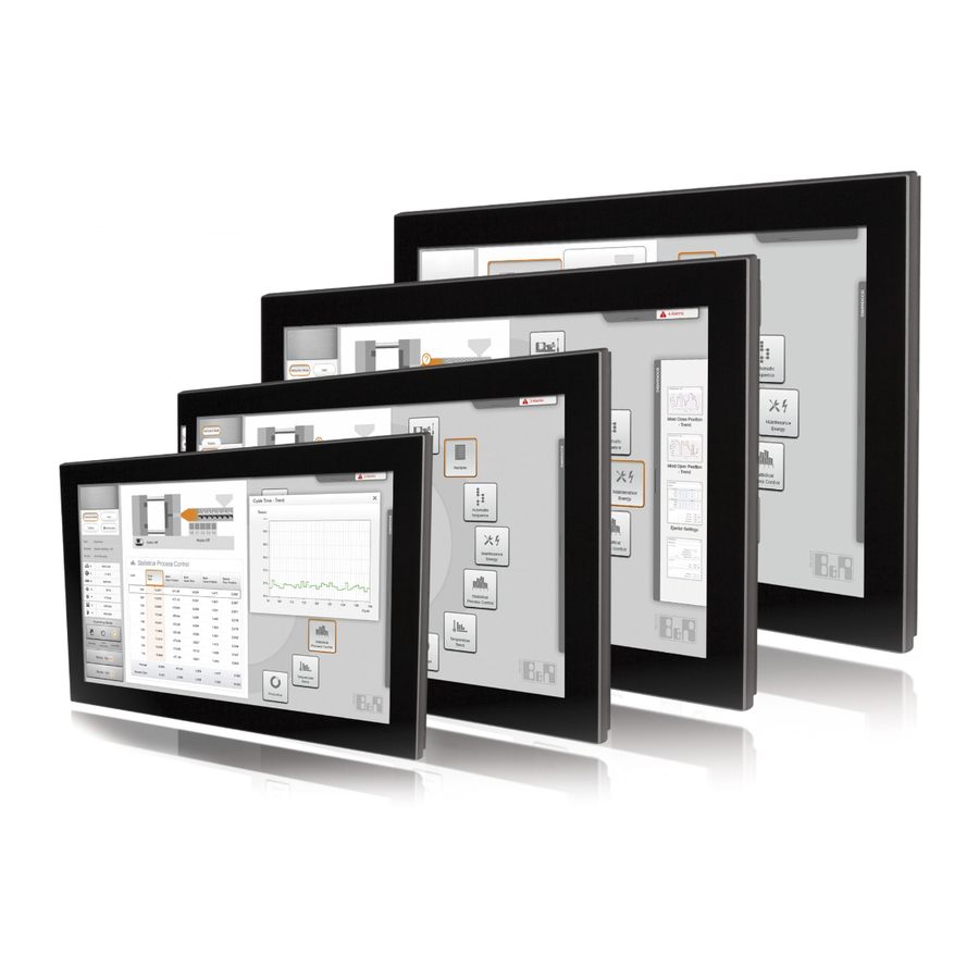
Technical data • Introduction 1.3 System components / Configuration 1.3.1 Configuration The following components are required for operation as a Panel PC 2100 swing arm device: • Display unit • System unit • CFast card for the operating system • Operating system... - Page 19 1) Handles are not factory-installed and must be mounted after delivery. 2) The terminal block is optional and used to make the connection to the button/switch interface. Figure 1: Panel PC 2100 swing arm device - Configuration Panel PC 2100 swing arm user's manual V1.12...
-
Page 20: Complete System
38.8 314.4 738.5 35.5 Table 5: PPC 2100 swing arm device display units - Dimensions Information: 2D and 3D drawings (in DXF and STEP format) can be downloaded from the B&R website (www.br-automation.com). Panel PC 2100 swing arm user's manual V1.12... - Page 21 477.5 30.25 35.5 elements 24.0" multi-touch with operating 5AP99D.240C-0x 626.5 197.5 231.5 24.5 38.8 397.4 738.5 35.5 elements Table 6: PPC 2100 swing arm device display units with operating elements - Dimensions Panel PC 2100 swing arm user's manual V1.12...
- Page 22 Technical data • Complete system Information: 2D and 3D drawings (in DXF and STEP format) can be downloaded from the B&R website (www.br-automation.com). Panel PC 2100 swing arm user's manual V1.12...
-
Page 23: Mounting Orientations
The screw in the adjustment lever is not permitted to be tightened. Only the adjustment lever can be used to lock into position. Figure 4: Panel PC 2100 swing arm device - Angle of rotation Panel PC 2100 swing arm user's manual V1.12... -
Page 24: Weight Specifications
For 5AP92D.1505-xx 5AC903.HDL0-00 For 5AP92D.1906-xx 5AC903.HDL0-01 For 5AP93D.185B-0x 5AC903.HDL0-02 For 5AP93D.215C-0x 5AC903.HDL0-03 For 5AP93D.240C-0x 5AC903.HDL0-04 For 5AP99D.185B-0x 5AC903.HDL0-05 For 5AP99D.215C-0x 5AC903.HDL0-06 For 5AP99D.215I-0x 5AC903.HDL0-07 1200 For 5AP99D.240C-0x 5AC903.HDL0-08 Table 9: Handles - Weight Panel PC 2100 swing arm user's manual V1.12... -
Page 25: Environmental Characteristics
5ACCIF01.FPSC-001 ✓ ✓ 5ACCIF01.ICAN-000 1) A total derating of 5°C applies when using 5PPC2100.BY34-001 or 5PPC2100.BY44-001 with 5AP99D.215C-0x and 5ACCIF01.FPLS-000, 5ACCIF01.FPLS-001 or 5ACCIF01.FPSC-000, 5ACCIF01.FPSC-001. Table 10: Maximum ambient temperature for worst-case operation Panel PC 2100 swing arm user's manual V1.12... - Page 26 3. Incorporating additional interface options and CFast cards can change the temperature limits of a PPC2100 system. 4. The mounting orientation of the Panel PC 2100 may result in limitations. For more information, see section "Mounting orientations" on page If there is a "✓" next to the component, it can be used at the minimum/maximum ambient temperature of the complete system without problems.
- Page 27 Sensors monitor temperature values at various locations in the PPC2100 swing arm device. The location of these temperature sensors is illustrated in Fig. 5 "Panel PC 2100 swing arm device - Temperature sensor positions" on page 28. The values listed in "Temperature sensor locations"...
- Page 28 Technical data • Complete system 2.2.1.6 Temperature sensor positions Figure 5: Panel PC 2100 swing arm device - Temperature sensor positions ADI sensors Position Measurement Measurement Max. specified point for Panel Display Temperature of the display (sensor integrated in display unit) 5AP92D.1505-0x: 92°C...
-
Page 29: Humidity
This value applies to a device in its original packaging. 2.2.5 Protection The Panel PC 2100 swing arm device is rated IP65 in accordance with EN 60529 on all sides under the following conditions: Panel PC 2100 swing arm user's manual V1.12... - Page 30 • All covers and components are installed on the interfaces and slots. • All environmental conditions are being observed. The Panel PC 2100 with AP92D display unit also has "Type 4X indoor use only" in accordance with UL 50 on the front under the same conditions.
-
Page 31: Electrical Characteristics
Nominal current 3.5 A Inrush current Typ. 6 A; max. 10 A for <300 μs Overvoltage category in accordance with EN 61131-2 Electrical isolation Uninterruptible power supply EN 60950 requirements must be observed. Panel PC 2100 swing arm user's manual V1.12... -
Page 32: Power Calculation
Technical data • Complete system 2.3.2 Power calculation In order to calculate the total power of the Panel PC 2100 swing arm device, the power rating of the display being used (see "Display units - Power calculation") must be added to the power ratings of the system unit or CFast card being used and any connected interface options. - Page 33 Technical data • Complete system Example 15" 5AP92D.1505-0x display unit 2.10 W + 8.90 W = 11 W 5PPC2100.BY11-001 system unit 23 W (with USB consumers) 23 W CFast card 1.00 W Total max.: 35 W Panel PC 2100 swing arm user's manual V1.12...
-
Page 34: Block Diagrams
POWERLINK Power down Female connector, Isolator CAN1 10-pin CAN2 nvSRAM Isolator Terminating L1 LED L2 LED L3 LED Yellow Green Green/Red resistor Figure 7: IF option POWERLINK/2x CAN/X2X/nvSRAM (5ACCIF01.FPCC-000) - Block diagram Panel PC 2100 swing arm user's manual V1.12... - Page 35 IF option POWERLINK / RS232 / nvSRAM PCIe 1 FPGA POWERLINK Power down Female connector, nvSRAM RS232 10-pin F_I0 L2 LED L3 LED Green Green/Red Figure 11: IF option POWERLINK / RS232 / nvSRAM (5ACCIF01.FPLS-001) - Block diagram Panel PC 2100 swing arm user's manual V1.12...
- Page 36 Figure 13: IF option POWERLINK / RS232 / CAN / X2X / nvSRAM (5ACCIF01.FPSC-001) - Block diagram IF option CAN 82527 PCIe 1 Intel 82527 Power down Female connector, Isolator 10-pin Terminating L1 LED Yellow resistor Figure 14: IF option CAN (5ACCIF01.ICAN-000) - Block diagram Panel PC 2100 swing arm user's manual V1.12...
-
Page 37: Device Interfaces And Slots
2.4 Device interfaces and slots 2.4.1 Device interfaces - Overview Interfaces are located on the back of the Panel PC 2100. To access it, the interface cover on the back must be removed first (see "Removing the interface cover" on page 134). -
Page 38: Vdc Power Supply
The ground connection must be used, for example, to fasten a copper strip to a central grounding point in the control cabinet or system where the device is installed. The largest possible conductor cross section should be used (at least 2.5 mm²). Panel PC 2100 swing arm user's manual V1.12... -
Page 39: Ethernet 1 Interface (Eth1)
A special driver is required to operate the Ethernet controller. Drivers for approved operating systems are available in the Downloads section of the B&R website (www.br-automation.com). Information: Required drivers must be downloaded from the B&R website only, not from manufacturer websites. Panel PC 2100 swing arm user's manual V1.12... -
Page 40: Usb Interfaces
With revisions < A2 for 5PPC2100.BY44-001 system units, the max. cable length has been specified at 3 m. Front USB Display units with operating elements are equipped with a USB 2.0 interface on the front. For more information, see section "USB interface" on page Panel PC 2100 swing arm user's manual V1.12... -
Page 41: Cfast Slot
Pushing the reset button triggers a hardware and PCI reset. The Panel PC is restarted (cold restart). Pressing the reset button does not reset the MTCX processor. Reset button Table 31: Reset button Warning! A system reset can result in lost data! Panel PC 2100 swing arm user's manual V1.12... -
Page 42: Led Status Indicators
Controlled by Automation Runtime (ARemb and ARwin) Application in service mode Controlled by Automation Runtime (ARemb and ARwin) Orange Blinking Indicates a licensing violation Controlled by Automation Runtime (ARemb and ARwin) Table 32: LED status indicators - Data Panel PC 2100 swing arm user's manual V1.12... -
Page 43: If Option Slot (If1, Ifx)
- For APC2100/PPC2100 5ACCIF01.ICAN-000 Interface card - 1x CAN interface - For APC2100/ PPC2100 Table 33: IF1 IF option, IFx slot Information: Interface options can only be installed and replaced by B&R. Panel PC 2100 swing arm user's manual V1.12... -
Page 44: Components On Display Units With Operating Elements
The positions of buttons and LEDs in the matrix are shown as hardware numbers. These hardware numbers can be read directly from the target system using the B&R Key Editor, B&R KCF Editor or B&R Control Center. Panel PC 2100 swing arm user's manual V1.12... - Page 45 Figure 18: Display - Keys and LEDs The configuration below applies to the following display units: • 5AP99D.185B-00 / -01 • 5AP99D.215C-00 / -01 • 5AP99D.240C-00 / -01 Figure 19: AP99D (landscape) - Button, switch and LED configuration Panel PC 2100 swing arm user's manual V1.12...
- Page 46 Technical data • Complete system The configuration below applies to the following display unit: • 5AP99D.215I-00 / -01 Figure 20: AP99D (portrait) - Button, switch and LED configuration Panel PC 2100 swing arm user's manual V1.12...
-
Page 47: Usb Interface
With revisions < A1 for 5PPC2100.BY22-001 and 5PPC2100.BY34-001 system units, the max. cable length has been specified at 2 m. With revisions < A2 for 5PPC2100.BY44-001 system units, the max. cable length has been specified at 2 m. Panel PC 2100 swing arm user's manual V1.12... -
Page 48: Button/Switch Interface
Transponder tag, red housing, MIFARE Classic, 1 kB, 13.56 MHz read/write 5A9020.47 Transponder tag, green housing, MIFARE Classic, 1 kB, 13.56 MHz read/write 5A9020.48 Transponder tag, blue housing, MIFARE Classic, 1 kB, 13.56 MHz read/write Panel PC 2100 swing arm user's manual V1.12... -
Page 49: Individual Components
Pollution degree 2 EN 60529 protection IP65 UL 50 protection Front: Type 4X indoor use only Mechanical characteristics Housing Material Aluminum, painted Coating White aluminum Table 37: 5AP92D.1505-00, 5AP92D.1505-01 - Technical data Panel PC 2100 swing arm user's manual V1.12... - Page 50 Only when all covers are installed and the device is properly mounted on a swing arm. 3.1.1.4 Dimensions Figure 22: 5AP92D.1505-0x - Dimensions 3.1.1.5 Temperature/Humidity diagram Operation Temperature [°C] Figure 23: 5AP92D.1505-0x - Temperature/Humidity diagram Panel PC 2100 swing arm user's manual V1.12...
-
Page 51: 5Ap92D.1906-0X
Housing Material Aluminum, painted Coating White aluminum Front Frame Aluminum, painted Panel overlay Material Polyester Dark gray border around display RAL 7024 Flange output Bottom Table 39: 5AP92D.1906-00, 5AP92D.1906-01 - Technical data Panel PC 2100 swing arm user's manual V1.12... - Page 52 Only when all covers are installed and the device is properly mounted on a swing arm. 3.1.2.4 Dimensions Figure 24: 5AP92D.1906-0x - Dimensions 3.1.2.5 Temperature/Humidity diagram Operation Temperature [°C] Figure 25: 5AP92D.1906-0x - Temperature/Humidity diagram Panel PC 2100 swing arm user's manual V1.12...
-
Page 53: 5Ap93D.185B-0X
At an ambient temperature of 25°C. Reducing the brightness by 50% can result in an approximately 50% increase in the half-brightness time. Only when all covers are installed and the device is properly mounted on a swing arm. Panel PC 2100 swing arm user's manual V1.12... - Page 54 Technical data • Individual components 3.1.3.4 Dimensions Figure 26: 5AP93D.185B-0x - Dimensions 3.1.3.5 Temperature/Humidity diagram Operation -80 -70 -60 -50 -40 -30 -20 -10 40 50 Temperature [°C] Figure 27: 5AP93D.185B-0x - Temperature/Humidity diagram Panel PC 2100 swing arm user's manual V1.12...
-
Page 55: 5Ap93D.215C-0X
At an ambient temperature of 25°C. Reducing the brightness by 50% can result in an approximately 50% increase in the half-brightness time. Only when all covers are installed and the device is properly mounted on a swing arm. Panel PC 2100 swing arm user's manual V1.12... - Page 56 Technical data • Individual components 3.1.4.4 Dimensions 569.5 Figure 28: 5AP93D.215C-0x - Dimensions 3.1.4.5 Temperature/Humidity diagram Operation -80 -70 -60 -50 -40 -30 -20 -10 40 50 Temperature [°C] Figure 29: 5AP93D.215C-0x - Temperature/Humidity diagram Panel PC 2100 swing arm user's manual V1.12...
-
Page 57: 5Ap93D.240C-0X
At an ambient temperature of 25°C. Reducing the brightness by 50% can result in an approximately 50% increase in the half-brightness time. Only when all covers are installed and the device is properly mounted on a swing arm. Panel PC 2100 swing arm user's manual V1.12... - Page 58 Technical data • Individual components 3.1.5.4 Dimensions 626.5 Figure 30: 5AP93D.240C-0x - Dimensions 3.1.5.5 Temperature/Humidity diagram Operation -80 -70 -60 -50 -40 -30 -20 -10 40 50 Temperature [°C] Figure 31: 5AP93D.240C-0x - Temperature/Humidity diagram Panel PC 2100 swing arm user's manual V1.12...
-
Page 59: 5Ap99D.185B-0X
Brightness (dimmable) Typ. 15 to 300 cd/m² Half-brightness time 50,000 h Touch screen Type Technology Projected capacitive touch (PCT) Controller Transmittance See appendix A "Touch screen". Table 47: 5AP99D.185B-00, 5AP99D.185B-01 - Technical data Panel PC 2100 swing arm user's manual V1.12... - Page 60 Additional information about operating and switching elements can be found in section "Equipment" of "Appendix A" in the user's manual. Only when all covers are installed and the device is properly mounted on a swing arm. 3.1.6.4 Dimensions Figure 32: 5AP99D.185B-0x - Dimensions Panel PC 2100 swing arm user's manual V1.12...
- Page 61 Technical data • Individual components 3.1.6.5 Temperature/Humidity diagram Operation -80 -70 -60 -50 -40 -30 -20 -10 40 50 Temperature [°C] Figure 33: 5AP99D.185B-0x - Temperature/Humidity diagram Panel PC 2100 swing arm user's manual V1.12...
-
Page 62: 5Ap99D.215C-0X
Brightness (dimmable) Typ. 12.5 to 250 cd/m² Half-brightness time 30,000 h Touch screen Type Technology Projected capacitive touch (PCT) Controller Transmittance See appendix A "Touch screen". Table 49: 5AP99D.215C-00, 5AP99D.215C-01 - Technical data Panel PC 2100 swing arm user's manual V1.12... - Page 63 Additional information about operating and switching elements can be found in section "Equipment" of "Appendix A" in the user's manual. Only when all covers are installed and the device is properly mounted on a swing arm. 3.1.7.4 Dimensions 569.5 Figure 34: 5AP99D.215C-0x - Dimensions Panel PC 2100 swing arm user's manual V1.12...
- Page 64 Technical data • Individual components 3.1.7.5 Temperature/Humidity diagram Operation -80 -70 -60 -50 -40 -30 -20 -10 40 50 Temperature [°C] Figure 35: 5AP99D.215C-0x - Temperature/Humidity diagram Panel PC 2100 swing arm user's manual V1.12...
-
Page 65: 5Ap99D.215I-0X
Brightness (dimmable) Typ. 12.5 to 250 cd/m² Half-brightness time 30,000 h Touch screen Type Technology Projected capacitive touch (PCT) Controller Transmittance See appendix A "Touch screen". Table 51: 5AP99D.215I-00, 5AP99D.215I-01 - Technical data Panel PC 2100 swing arm user's manual V1.12... - Page 66 Additional information about operating and switching elements can be found in section "Equipment" of "Appendix A" in the user's manual. Only when all covers are installed and the device is properly mounted on a swing arm. Panel PC 2100 swing arm user's manual V1.12...
- Page 67 Technical data • Individual components 3.1.8.4 Dimensions Figure 36: 5AP99D.215I-0x - Dimensions 3.1.8.5 Temperature/Humidity diagram Operation -80 -70 -60 -50 -40 -30 -20 -10 40 50 Temperature [°C] Figure 37: 5AP99D.215I-0x - Temperature/Humidity diagram Panel PC 2100 swing arm user's manual V1.12...
-
Page 68: 5Ap99D.240C-0X
Brightness (dimmable) Typ. 30 to 300 cd/m² Half-brightness time 50,000 h Touch screen Type Technology Projected capacitive touch (PCT) Controller Transmittance See appendix A "Touch screen". Table 53: 5AP99D.240C-00, 5AP99D.240C-01 - Technical data Panel PC 2100 swing arm user's manual V1.12... - Page 69 Additional information about operating and switching elements can be found in section "Equipment" of "Appendix A" in the user's manual. Only when all covers are installed and the device is properly mounted on a swing arm. Panel PC 2100 swing arm user's manual V1.12...
- Page 70 Technical data • Individual components 3.1.9.4 Dimensions 626.5 Figure 38: 5AP99D.240C-0x - Dimensions 3.1.9.5 Temperature/Humidity diagram Operation -80 -70 -60 -50 -40 -30 -20 -10 40 50 Temperature [°C] Figure 39: 5AP99D.240C-0x - Temperature/Humidity diagram Panel PC 2100 swing arm user's manual V1.12...
-
Page 71: System Units
Panel PC 2100 - Intel Atom E3815 1.46 GHz - Single core - 1 GB SDRAM - For Automation Panel swing arm devices 5PPC2100.BY11-001 Panel PC 2100 - Intel Atom E3825 1.33 GHz - Dual core - 1 GB SDRAM - For Automation Panel swing arm devices 5PPC2100.BY22-001 Panel PC 2100 - Intel Atom E3826 1.46 GHz - Dual core - 2 GB... - Page 72 Typ. 6 A; max. 10 A for <300 μs Overvoltage category in accordance with EN 61131-2 Electrical isolation Operating conditions EN 61131 pollution degree Pollution degree 2 Table 55: 5PPC2100.BY01-001, 5PPC2100.BY11-001, 5PPC2100.BY22-001, 5PPC2100.BY34-001, 5PPC2100.BY44-001 - Technical data Panel PC 2100 swing arm user's manual V1.12...
- Page 73 EN 60950 requirements must be observed, see section "+24 VDC power supply" section in the user's manual. The maximum ambient temperature is typically derated by 1°C per 1000 meters (starting at 500 meters above sea level). Panel PC 2100 swing arm user's manual V1.12...
-
Page 74: Cfast Cards
Self-Monitoring, Analysis and Reporting Technology (S.M.A.R.T.) is an industry standard for mass storage devices that has been introduced to monitor important parameters and quickly detect imminent failures. Critical performance and calibration data is monitored and stored in order to help predict the probability of errors. Panel PC 2100 swing arm user's manual V1.12... - Page 75 3.3.2.6 Dimensions 42.8 ±0.1 2.3 ±0.1 +0.2 -0.1 1.15 ±0.1 1 ±0.1 41.6 ±0.13 0.6 ±0.07 1 ±0.07 1 ±0.07 Bottom 1 ±0.1 6.35 33.96 ±0.15 Figure 40: CFast card - Dimensions Panel PC 2100 swing arm user's manual V1.12...
-
Page 76: 5Cfast.xxxx-00
95 MB/s 95 MB/s 95 MB/s 120 MB/s With 4 kB block size 40 MB/s 45 MB/s 45 MB/s 45 MB/s 45 MB/s Table 57: 5CFAST.2048-00, 5CFAST.4096-00, 5CFAST.8192-00, 5CFAST.016G-00, 5CFAST.032G-00 - Technical data Panel PC 2100 swing arm user's manual V1.12... - Page 77 Yes, although applies only if all components installed within the complete system have this certification and the complete system itself carries the corresponding mark. Yes, although applies only if all components installed within the complete system have this certification. TBW = Terabytes written. Sequential access without a file system. Panel PC 2100 swing arm user's manual V1.12...
- Page 78 3.3.3.5 Dimensions 42.8 ±0.1 2.3 ±0.1 +0.2 -0.1 1.15 ±0.1 1 ±0.1 41.6 ±0.13 0.6 ±0.07 1 ±0.07 1 ±0.07 Bottom 1 ±0.1 6.35 33.96 ±0.15 Figure 42: CFast card - Dimensions Panel PC 2100 swing arm user's manual V1.12...
-
Page 79: 5Cfast.xxxx-10
SATA 3, SATA 2, SATA 1 Sequential read Maximum 495 MB/s 500 MB/s 500 MB/s 500 MB/s Sequential write Maximum 115 MB/s 100 MB/s 195 MB/s 330 MB/s Table 60: 5CFAST.032G-10, 5CFAST.064G-10, 5CFAST.128G-10, 5CFAST.256G-10 - Technical data Panel PC 2100 swing arm user's manual V1.12... - Page 80 Yes, although applies only if all components installed within the complete system have this certification. TBW = Terabytes written. Sequential access without a file system. TBW = Terabytes written. Client workload according to JEDEC JESD219 standard Panel PC 2100 swing arm user's manual V1.12...
- Page 81 7 to 2000 Hz: 20 g peak Shock Operation 1500 g peak, 0.5 ms Storage 1500 g peak, 0.5 ms Transport 1500 g peak, 0.5 ms Table 61: 5CFAST.032G-10, 5CFAST.064G-10, 5CFAST.128G-10 - Technical data Panel PC 2100 swing arm user's manual V1.12...
- Page 82 Figure 43: 5CFAST.032G-10 ≥Rev. G0, 5CFAST.064G-10 ≥Rev. E0, 5CFAST.128G-10 ≥Rev. E0, 5CFAST.256G-10 - Temperature/Humidity diagram Operation Temperature [°C] Figure 44: 5CFAST.032G-10 ≤Rev. F0, 5CFAST.064G-10 ≤Rev. D0, 5CFAST.128G-10 ≤Rev. D0 - Temperature/Humidity diagram Panel PC 2100 swing arm user's manual V1.12...
- Page 83 If an operating system is installed on the CFast card, write protection must be disabled. Disabled Enabled Figure 45: CFast card - Write protection Write protection is only present on the following CFast cards: • 5CFAST.032G-10 ≤Rev. F0 • 5CFAST.064G-10 ≤Rev. D0 • 5CFAST.128G-10 ≤Rev. D0 Panel PC 2100 swing arm user's manual V1.12...
-
Page 84: Interface Options
Class I, Division 2, Groups ABCD, T4 Controller nvSRAM Size 512 kB Remanent variables in power failure mode 256 kB (for e.g. Automation Runtime, see Automation Help) Table 63: 5ACCIF01.FPCC-000 - Technical data Panel PC 2100 swing arm user's manual V1.12... - Page 85 The interfaces, etc. available on the device or module have been numbered as such for easy identification. This numbering may differ from that used by the particular operating system. This interface is referred to as IF1 in Automation Studio / Automation Runtime. Panel PC 2100 swing arm user's manual V1.12...
- Page 86 Table 67: CAN1 - Bus length and transfer rate The specified cable length is only valid with the values specified in Tab. 66 "CAN driver settings". Cable lengths additionally depend on the values in the timing register. Panel PC 2100 swing arm user's manual V1.12...
- Page 87 BIOS. CAN driver settings The baud rate can be set in Automation Studio either with predefined values or with the bit timing register. For additional information, see Automation Help. Panel PC 2100 swing arm user's manual V1.12...
- Page 88 This interface can only be used in Automation Runtime and is referred to as IF2 in Automation Studio / Automation Runtime. It is not a "PC interface" and therefore not shown in BIOS. 3.4.1.3.5 Shielding For the interfaces on the 10-pin female connector, the interface shield can be put on pin 2 of the female connector. Panel PC 2100 swing arm user's manual V1.12...
- Page 89 If an error occurs in the following states, then the green LED blinks over the red LED: • BASIC_ETHERNET • PRE_OPERATIONAL_1 • PRE_OPERATIONAL_2 • READY_TO_OPERATE Status Green Error LED "S/E" Table 77: Status/Error LED - POWERLINK - Error Panel PC 2100 swing arm user's manual V1.12...
- Page 90 No output data is being produced, and no input data is being received. It is only possible to enter or leave this mode after the MN has given the appropriate command. Table 78: Status/Error LED - POWERLINK - Status Panel PC 2100 swing arm user's manual V1.12...
- Page 91 The firmware is a component of Automation Studio. The module is updated to this version automatically. To update the firmware included in Automation Studio, the hardware must be upgraded (see "Project manage- ment" / "The workspace" / "Upgrades" in Automation Help). Panel PC 2100 swing arm user's manual V1.12...
-
Page 92: 5Accif01.Fpcs-000
Terminating resistor Type Can be enabled or disabled using a slide switch Electrical characteristics Power consumption 1.75 W Operating conditions EN 61131 pollution degree Pollution degree 2 Table 81: 5ACCIF01.FPCS-000 - Technical data Panel PC 2100 swing arm user's manual V1.12... - Page 93 This interface can only be used in Automation Runtime and is referred to as IF7 in Automation Studio / Automation Runtime. It is not a "PC interface" and therefore not shown in BIOS. The RTS line must be switched by the driver for each transmission or reception; there is no automatic switch- back mechanism. Panel PC 2100 swing arm user's manual V1.12...
- Page 94 This interface can only be used in Automation Runtime and is referred to as IF3 in Automation Studio / Automation Runtime. It is not a "PC interface" and therefore not shown in BIOS. Panel PC 2100 swing arm user's manual V1.12...
- Page 95 For the interfaces on the 10-pin female connector, the interface shield can be put on pin 2 of the female connector. A functional ground connection, which can also be used for the cable shields, is located on the interface plate of the system unit. Panel PC 2100 swing arm user's manual V1.12...
- Page 96 If an error occurs in the following states, then the green LED blinks over the red LED: • BASIC_ETHERNET • PRE_OPERATIONAL_1 • PRE_OPERATIONAL_2 • READY_TO_OPERATE Status Green Error LED "S/E" Table 93: Status/Error LED - POWERLINK - Error Panel PC 2100 swing arm user's manual V1.12...
- Page 97 No output data is being produced, and no input data is being received. It is only possible to enter or leave this mode after the MN has given the appropriate command. Table 94: Status/Error LED - POWERLINK - Status Panel PC 2100 swing arm user's manual V1.12...
- Page 98 The firmware is a component of Automation Studio. The module is updated to this version automatically. To update the firmware included in Automation Studio, the hardware must be upgraded (see "Project manage- ment" / "The workspace" / "Upgrades" in Automation Help). Panel PC 2100 swing arm user's manual V1.12...
-
Page 99: 5Accif01.Fplk-000
Class I, Division 2, Groups ABCD, T4 Controller nvSRAM Size 512 kB Remanent variables in power failure mode 256 kB (for e.g. Automation Runtime, see Automation Help) Table 97: 5ACCIF01.FPLK-000 - Technical data Panel PC 2100 swing arm user's manual V1.12... - Page 100 Table 99: 5ACCIF01.FPLK-000 - POWERLINK 2 interface The interfaces, etc. available on the device or module have been numbered as such for easy identification. This numbering may differ from that used by the particular operating system. Panel PC 2100 swing arm user's manual V1.12...
- Page 101 If an error occurs in the following states, then the green LED blinks over the red LED: • BASIC_ETHERNET • PRE_OPERATIONAL_1 • PRE_OPERATIONAL_2 • READY_TO_OPERATE Status Green Error LED "S/E" Table 102: Status/Error LED - POWERLINK - Error Panel PC 2100 swing arm user's manual V1.12...
- Page 102 No output data is being produced, and no input data is being received. It is only possible to enter or leave this mode after the MN has given the appropriate command. Table 103: Status/Error LED - POWERLINK - Status Panel PC 2100 swing arm user's manual V1.12...
- Page 103 The firmware is a component of Automation Studio. The module is updated to this version automatically. To update the firmware included in Automation Studio, the hardware must be upgraded (see "Project manage- ment" / "The workspace" / "Upgrades" in Automation Help). Panel PC 2100 swing arm user's manual V1.12...
-
Page 104: 5Accif01.Fpls-000
Type Type 4 Design Shielded RJ45 Transfer rate 100 Mbit/s Cable length Max. 100 m between two stations (segment length) Electrical characteristics Power consumption 1.5 W Table 106: 5ACCIF01.FPLS-000 - Technical data Panel PC 2100 swing arm user's manual V1.12... - Page 105 This interface (if available) is enabled automatically in BIOS as COMA with default I/O address 3F8h and IRQ 4. This interface is referred to as IF5 in Automation Studio / Automation Runtime. Panel PC 2100 swing arm user's manual V1.12...
- Page 106 If an error occurs in the following states, then the green LED blinks over the red LED: • BASIC_ETHERNET • PRE_OPERATIONAL_1 • PRE_OPERATIONAL_2 • READY_TO_OPERATE Status Green Error LED "S/E" Table 111: Status/Error LED - POWERLINK - Error Panel PC 2100 swing arm user's manual V1.12...
- Page 107 No output data is being produced, and no input data is being received. It is only possible to enter or leave this mode after the MN has given the appropriate command. Table 112: Status/Error LED - POWERLINK - Status Panel PC 2100 swing arm user's manual V1.12...
- Page 108 The firmware is a component of Automation Studio. The module is updated to this version automatically. To update the firmware included in Automation Studio, the hardware must be upgraded (see "Project manage- ment" / "The workspace" / "Upgrades" in Automation Help). Panel PC 2100 swing arm user's manual V1.12...
-
Page 109: 5Accif01.Fpls-001
100 Mbit/s Cable length Max. 100 m between two stations (segment length) Electrical characteristics Power consumption 1.5 W Operating conditions EN 61131 pollution degree Pollution degree 2 Table 115: 5ACCIF01.FPLS-001 - Technical data Panel PC 2100 swing arm user's manual V1.12... - Page 110 This interface (if available) is enabled automatically in BIOS as COMA with default I/O address 3F8h and IRQ 4. This interface is referred to as IF5 in Automation Studio / Automation Runtime. Panel PC 2100 swing arm user's manual V1.12...
- Page 111 If an error occurs in the following states, then the green LED blinks over the red LED: • BASIC_ETHERNET • PRE_OPERATIONAL_1 • PRE_OPERATIONAL_2 • READY_TO_OPERATE Status Green Error LED "S/E" Table 120: Status/Error LED - POWERLINK - Error Panel PC 2100 swing arm user's manual V1.12...
- Page 112 No output data is being produced, and no input data is being received. It is only possible to enter or leave this mode after the MN has given the appropriate command. Table 121: Status/Error LED - POWERLINK - Status Panel PC 2100 swing arm user's manual V1.12...
- Page 113 The firmware is a component of Automation Studio. The module is updated to this version automatically. To update the firmware included in Automation Studio, the hardware must be upgraded (see "Project manage- ment" / "The workspace" / "Upgrades" in Automation Help). Panel PC 2100 swing arm user's manual V1.12...
-
Page 114: 5Accif01.Fpsc-000
115 kbit/s POWERLINK Quantity Transmission 100BASE-TX Type Type 4 Design Shielded RJ45 Transfer rate 100 Mbit/s Cable length Max. 100 m between two stations (segment length) Table 124: 5ACCIF01.FPSC-000 - Technical data Panel PC 2100 swing arm user's manual V1.12... - Page 115 The interfaces, etc. available on the device or module have been numbered as such for easy identification. This numbering may differ from that used by the particular operating system. This interface is referred to as IF1 in Automation Studio / Automation Runtime. Panel PC 2100 swing arm user's manual V1.12...
- Page 116 In accordance with CiA (CAN in Automation), the maximum bus length is 1000 meters. The following bus lengths are permitted with a maximum oscillator tolerance of 0.121%: Panel PC 2100 swing arm user's manual V1.12...
- Page 117 LED". Table 132: 5ACCIF01.FPSC-000 - LED status indicators Status/Error LED The Status/Error LED is a green and red dual LED. The LED status can have different meanings depending on the operating mode. Panel PC 2100 swing arm user's manual V1.12...
- Page 118 The module can be configured by the MN in this state. The CN waits until it receives an SoC frame and then switches to state PRE_OPERATIONAL_2 (double flash). An LED lit red in this state indicates failure of the MN. Table 135: Status/Error LED - POWERLINK - Status Panel PC 2100 swing arm user's manual V1.12...
- Page 119 The firmware is a component of Automation Studio. The module is updated to this version automatically. To update the firmware included in Automation Studio, the hardware must be upgraded (see "Project manage- ment" / "The workspace" / "Upgrades" in Automation Help). Panel PC 2100 swing arm user's manual V1.12...
-
Page 120: 5Accif01.Fpsc-001
115 kbit/s POWERLINK Quantity Transmission 100BASE-TX Type Type 4 Design Shielded RJ45 Transfer rate 100 Mbit/s Cable length Max. 100 m between two stations (segment length) Table 138: 5ACCIF01.FPSC-001 - Technical data Panel PC 2100 swing arm user's manual V1.12... - Page 121 The interfaces, etc. available on the device or module have been numbered as such for easy identification. This numbering may differ from that used by the particular operating system. This interface is referred to as IF1 in Automation Studio / Automation Runtime. Panel PC 2100 swing arm user's manual V1.12...
- Page 122 In accordance with CiA (CAN in Automation), the maximum bus length is 1000 meters. The following bus lengths are permitted with a maximum oscillator tolerance of 0.121%: Panel PC 2100 swing arm user's manual V1.12...
- Page 123 For the interfaces on the 10-pin female connector, the interface shield can be put on pin 2 of the female connector. A functional ground connection, which can also be used for the cable shields, is located on the interface plate of the system unit. Panel PC 2100 swing arm user's manual V1.12...
- Page 124 If an error occurs in the following states, then the green LED blinks over the red LED: • BASIC_ETHERNET • PRE_OPERATIONAL_1 • PRE_OPERATIONAL_2 • READY_TO_OPERATE Status Green Error LED "S/E" Table 149: Status/Error LED - POWERLINK - Error Panel PC 2100 swing arm user's manual V1.12...
- Page 125 No output data is being produced, and no input data is being received. It is only possible to enter or leave this mode after the MN has given the appropriate command. Table 150: Status/Error LED - POWERLINK - Status Panel PC 2100 swing arm user's manual V1.12...
- Page 126 The firmware is a component of Automation Studio. The module is updated to this version automatically. To update the firmware included in Automation Studio, the hardware must be upgraded (see "Project manage- ment" / "The workspace" / "Upgrades" in Automation Help). Panel PC 2100 swing arm user's manual V1.12...
-
Page 127: 5Accif01.Ican-000
25 g Table 153: 5ACCIF01.ICAN-000 - Technical data Yes, although applies only if all components installed within the complete system have this certification and the complete system itself carries the corresponding mark. Panel PC 2100 swing arm user's manual V1.12... - Page 128 Extension Transfer rate ≤1000 m Typ. 50 kbit/s ≤200 m Typ. 250 kbit/s ≤100 m Typ. 500 kbit/s ≤20 m Typ. 1 Mbit/s Table 157: CAN - Bus length and transfer rate Panel PC 2100 swing arm user's manual V1.12...
- Page 129 • Automation PC 2100: V1.06 • Panel PC 2100: V1.06 This firmware can be downloaded from the B&R website (www.br-automation.com). Information about firmware upgrades can be found in section "Upgrading the firmware on the Panel PC 2100" on page 189. 3.4.8.3.5 Drivers In Windows 7 and later, the CAN IF option is supported by PVI V4.2.5 or Windows CAN driver V3.0.
-
Page 130: Handles
3.5.1 5AC903.HDL0-0x 3.5.1.1 General information Handles can be installed on the side of the Panel PC 2100 swing arm device to improve its ergonomic properties and ease of use. Handles are not factory-installed and must be mounted after delivery. For more information regarding installation, see the section "Installing the handles"... -
Page 131: Chapter 3 Commissioning
The swing arm shaft must have an outer diameter of 47.5 to 48.4. The end of the swing arm shaft that connects with the flange must be beveled at a 45° angle and deburred. Panel PC 2100 swing arm user's manual V1.12... - Page 132 (see "Installing the Panel PC 2100"). The distance from the bottom edge of the swing arm shaft and the bottom edge of the rotary swivel must be 21.5 mm ±0.5 mm (corresponds to a distance of 19 mm ±0.5 mm from the bottom edge of the swing arm shaft to the ring catch). There must be no space between the two rings.
-
Page 133: Separate Delivery Of Components
3. Connect the Panel PC to the swing arm system. The rings must be installed in such a way that the ring catch of the rotary swivel are to the left and right on the swing arm shaft. The Panel PC 2100 has been installed correctly if the upper ring is flush with the flange. -
Page 134: Removing The Interface Cover
4. Replace the interface cover on the Panel PC using the 9 to 12 Torx screws (T10) removed earlier (0.6 Nm tightening torque). The interface cover must be installed correctly to ensure IP65 protection. Panel PC 2100 swing arm user's manual V1.12... -
Page 135: Connecting The Cables
4. Replace the interface cover on the Panel PC using the 9 to 12 Torx screws (T10) removed earlier (0.6 Nm tightening torque). The interface cover must be installed correctly to ensure IP65 protection. Panel PC 2100 swing arm user's manual V1.12... -
Page 136: Replacing A System Unit
4. Disconnect all connected cables. 5. Disconnect the Panel PC from the swing arm system by following the steps provided under item 3 in section "Panel PC 2100 - Installation" on page 131 in reverse order. 6. Place the Panel PC on a clean, flat surface. - Page 137 11. Replace the interface cover on the Panel PC using the 9 to 12 Torx screws (T10) removed earlier (0.6 Nm tightening torque). The interface cover must be installed correctly to ensure IP65 protection. Panel PC 2100 swing arm user's manual V1.12...
-
Page 138: Installing The Handles
8. Insert the handle (③) with the mounted centering plates (②) in the mounting holes. 9. Insert the Torx screws (⑤, T20) through the previously mounted components and tighten with a max. tight- ening torque of 1.27 Nm. Figure 56: Installing the handles Panel PC 2100 swing arm user's manual V1.12... -
Page 139: Connecting To The Power Grid
Please note the pinout of the power supply connector on the device! Installing a cage clamp terminal block Cage clamp terminal blocks DC power cable 24 VDC Functional ground 0 VDC Terminal contacts Terminal block Figure 58: Installing a cage clamp terminal block Panel PC 2100 swing arm user's manual V1.12... -
Page 140: Connecting The Power Supply To A B&R Device
0TB103.9 or 0TB103.91 terminal block, then a cable with maximum 1.5 mm² per connection is possible. • Note the line shielding concept. All data cables connected to the device must be shielded. Symbol indicating functional ground on the B&R device: Panel PC 2100 swing arm user's manual V1.12... - Page 141 Commissioning • Connecting to the power grid Control cabinet Ground connection Power supply Grounding strip Min. 2.5 mm² Min. 1.5 mm² Figure 60: Panel PC 2100 swing arm device - Grounding concept Panel PC 2100 swing arm user's manual V1.12...
-
Page 142: Cable Connections
The maximum tightening torque for the locating screws is 0.5 Nm. Locating screws Bend radius Locating screws Figure 61: Bend radius - Cable connection Information: The specified bend radius is listed in the technical data for the respective cable. Panel PC 2100 swing arm user's manual V1.12... -
Page 143: Switching On The Device For The First Time
5. Replace the interface cover on the Panel PC using the 9 to 12 Torx screws (T10) removed earlier (0.6 Nm tightening torque). The interface cover must be installed correctly to ensure IP65 protection. Panel PC 2100 swing arm user's manual V1.12... -
Page 144: Touch Screen Calibration
Microsoft multi-touch drivers are installed when Windows Embedded Standard 7 Premium is installed on the device. Once the installation of Windows Embedded Standard 7 Premium has completed, the device can be operated immediately. Panel PC 2100 swing arm user's manual V1.12... -
Page 145: Adjusting The Display Brightness
The configured brightness is separate from the value configured in BIOS Setup, i.e. the value in BIOS is used until Windows boots. The value from BIOS is only applied the first time the Control Center is launched. Panel PC 2100 swing arm user's manual V1.12... -
Page 146: General Instructions For Performing Temperature Testing
A separate application can be developed if it is necessary to collect historical data. Information: Software development kits such as the ADI .NET SDK are available on the B&R website (www.br-au- tomation.com) to develop a separate application. Panel PC 2100 swing arm user's manual V1.12... -
Page 147: Evaluating With The Burnintest Tool From Passmark
The following screenshots are based on PassMark BurnInTest Pro V6 and a PPC2100 without IF options. Figure 64: Settings for PassMark BurnInTest Pro V6 using an PPC2100 without IF options Figure 65: Test overview of an PPC2100 without IF options Panel PC 2100 swing arm user's manual V1.12... - Page 148 Information: Serial loopback adapters are relatively easy to create. Simply connect several pins on the serial inter- face with wires. Panel PC 2100 swing arm user's manual V1.12...
-
Page 149: Evaluating Temperatures In Non-Windows Operating Systems
(several hours) before beginning the test. Panel PC 2100 swing arm user's manual V1.12... -
Page 150: Known Problems / Issues
Graphics (IGD) configuration - IGD turbo to Disabled. If BIOS setting Advanced - Graphics (IGD) configu- ration - IGD turbo is set to Disabled, the graphics performance of the system is noticeably reduced. Panel PC 2100 swing arm user's manual V1.12... -
Page 151: Chapter 4 Software
To enter BIOS Setup, the "F2" key must be pressed after the USB controller has been initialized as soon as the following message appears on the monitor (during POST): "F2=Setup" Figure 66: Boot screen 1.3 BIOS default settings Configuration options in bold typeface represent the default value. Panel PC 2100 swing arm user's manual V1.12... -
Page 152: Bios Setup Keys
Jumps to the last BIOS menu item or object Resets any changes Loads and configures CMOS default values for all BIOS settings Saves and exits Exits a submenu Table 164: BIOS-relevant keys Panel PC 2100 swing arm user's manual V1.12... -
Page 153: Main
The currently configured system time setting. Change the system time Sets system time format Battery-backed while the system is switched off; Hour:Minute:Second (hh:mm:ss) for details, see the technical data for the system unit. Table 165: Main Panel PC 2100 swing arm user's manual V1.12... -
Page 154: System Information
Displays the size of all main memory None Displays the size of the main memory in slot 1 None Displays the size of the main memory in slot 2 None Table 166: Main - System information Panel PC 2100 swing arm user's manual V1.12... -
Page 155: Advanced
Miscellaneous configura- Configures miscellaneous settings Enter Opens this submenu tion "Miscellaneous configuration" on page 177. Thermal configuration Configures temperature settings Enter Opens this submenu "Thermal configuration" on page 178. Table 167: Advanced Panel PC 2100 swing arm user's manual V1.12... -
Page 156: Oem Features
"Display board features" on page 162. IF board features Displays device-specific information for the IF Enter Opens this submenu option "IF board features" on page 166. Table 168: Advanced - OEM features Panel PC 2100 swing arm user's manual V1.12... - Page 157 Option for setting the behavior after a power fail- Stay off Does not start the PC on power-on Power on Restarts the PC on power-on Test interface None Table 169: Advanced - OEM features - Miscellaneous configuration Panel PC 2100 swing arm user's manual V1.12...
- Page 158 Displays the I/O address 384h/385h Permanent assignment. This setting cannot be changed. Displays the IRQ Permanent assignment. This setting cannot be changed. Table 170: Advanced - OEM features - Super I/O configuration Panel PC 2100 swing arm user's manual V1.12...
- Page 159 Opens this submenu "Statistical values" on page 160. Temperature values Displays current temperature values Enter Opens this submenu "Temperature values" on page 161. Table 171: Advanced - OEM features - System board features Panel PC 2100 swing arm user's manual V1.12...
- Page 160 Displays the runtime in hours None Power on cycles Displays the number of power-on cycles. Each None restart increases the counter by one. Table 172: Advanced - OEM features - System board features - Statistical values Panel PC 2100 swing arm user's manual V1.12...
- Page 161 Displays the current temperature of sensor 2 None (system unit sensor 1) in °C and °F (sensor near the CPU) Table 173: Advanced - OEM features - System board features - Temperature values Panel PC 2100 swing arm user's manual V1.12...
- Page 162 Opens this submenu "Temperature values" on page 164. Panel #15 Displays the panel properties Enter Opens this submenu "Panel #15" on page 165. Table 174: Advanced - OEM features - Display board features Panel PC 2100 swing arm user's manual V1.12...
- Page 163 Displays the runtime in hours None Power on cycles Displays the number of power-on cycles. Each None restart increases the counter by one. Table 175: Advanced - OEM features - Display board features - Statistical values Panel PC 2100 swing arm user's manual V1.12...
- Page 164 Configuration options Effect Sensor 1 Displays the current temperature of sensor 1 None (display or panel) in °C and °F Table 176: Advanced - OEM features - Display board features - Temperature values Panel PC 2100 swing arm user's manual V1.12...
- Page 165 Displays the available keys and LEDs for the None panel Temperature Displays the temperature of the panel in °C and None °F Table 177: Advanced - OEM features - Display board features - Panel #15 Panel PC 2100 swing arm user's manual V1.12...
- Page 166 Parent compatibility ID Displays the manufacturer ID None Statistical values Displays statistical values Enter Opens this submenu "Statistical values" on page 167. Table 178: Advanced - OEM features - IF board features Panel PC 2100 swing arm user's manual V1.12...
- Page 167 Displays the runtime in hours None Power on cycles Displays the number of power-on cycles. Each None restart increases the counter by one. Table 179: Advanced - OEM features - IF board features - Statistical values Panel PC 2100 swing arm user's manual V1.12...
-
Page 168: Cpu Configuration
None Technology nology is supported CPU power management CPU energy settings configuration Enter Opens this submenu "CPU power management" on page 169. Table 180: Advanced - CPU configuration PROCHOT = Processor hot. Panel PC 2100 swing arm user's manual V1.12... - Page 169 Maximum C-State C1. Processor is in sleep mode, switch between C0 and C1. Table 181: Advanced - CPU configuration - CPU power management This setting is only possible if C-States is set to Enabled. Panel PC 2100 swing arm user's manual V1.12...
-
Page 170: Graphics (Igd) Configuration
Disables this function boost Enabled Enables this function IGD - LCD control Configures PPC2100 display settings Enter Opens this submenu "IGD - LCD control" on page 171. Table 182: Advanced - Graphics (IGD) configuration Panel PC 2100 swing arm user's manual V1.12... - Page 171 DVI monitors are reconnected, even if only one of them was con- nected and enabled during a previous boot. Table 183: Advanced - Graphics (IGD) configuration - IGD configuration Panel PC 2100 swing arm user's manual V1.12...
-
Page 172: Lan
Disables this function. The Ethernet controller mode via the onboard Ethernet controller cannot switch on the system. (ETH1). Enabled Enables this function. The Ethernet controller can switch on the system. Table 184: Advanced - LAN Panel PC 2100 swing arm user's manual V1.12... -
Page 173: Pci Express Configuration
PCI Express root port 3 Configures PCI Express settings on port 3 Enter Opens this submenu (ETH1) (ETH1) "PCI Express root port 0 to 3" on page 174. Table 185: Advanced - PCI express configuration Panel PC 2100 swing arm user's manual V1.12... - Page 174 Assign INT to root port Option for enabling/disabling the IRQ for the Enabled Enables this function root port Disabled Disables this function Table 186: Advanced - PCI Express configuration - PCI Express root port Panel PC 2100 swing arm user's manual V1.12...
-
Page 175: Usb Configuration
Enables this USB interface USB port #3 Option for enabling/disabling the multi-touch or Disabled Disables this USB interface the optional front USB interface Enabled Enables this USB interface Table 187: Advanced - USB configuration Panel PC 2100 swing arm user's manual V1.12... -
Page 176: Sata Configuration
Enabled Enables hot plugging for SATA interface 1. De- bility terface 1 vices can be connected/disconnected during operation. Disabled Disables hot plugging for SATA interface 1 Table 188: Advanced - SATA configuration Panel PC 2100 swing arm user's manual V1.12... -
Page 177: Miscellaneous Configuration
This is not the case with 64-bit operat- ing systems. Disabled Extended temperature Option for configuring the RAM refresh rate for Default RAM refresh range extended temperature Enabled Increased RAM refresh Table 189: Advanced - Miscellaneous configuration Panel PC 2100 swing arm user's manual V1.12... -
Page 178: Thermal Configuration
63°C / 145°F, 71°C / 160°F, 79°C / 174°F, 85°C / 185°F, 87°C / 189°F, 90°C / 194°F, 95°C / 203°F, 103°C / 217°F Disabled Disables this function Table 190: Advanced - Thermal configuration Panel PC 2100 swing arm user's manual V1.12... -
Page 179: Security
Enabled Requires the user password to be entered when booting Table 191: Security This setting can only be configured if a supervisor password has been set. Panel PC 2100 swing arm user's manual V1.12... -
Page 180: Boot
Configures the boot order Enter Opens this submenu "Boot device priority" on page 181. Boot configuration Configures the boot settings Enter Opens this submenu "Boot configuration" on page 182. Table 192: Boot Panel PC 2100 swing arm user's manual V1.12... -
Page 181: Boot Device Priority
USBHDD P0: "-". "Shift + 1" enables/disables a boot device. USBHDD P1: USBHDD P2: USBHDD P3: ATAPI CD: SATA HDD1: PCI LAN0: PCI LAN1: Internal shell Table 193: Boot - Boot device priority Panel PC 2100 swing arm user's manual V1.12... -
Page 182: Boot Configuration
This function is only possible with the 5ACCIF01.FPLS-000 or 5ACCIF01.F- PLS-001 IF option. Port console Option for configuring the serial interface Allows access via any serial interface Table 194: Boot - Boot configuration Panel PC 2100 swing arm user's manual V1.12... - Page 183 EFI boot services (approx. 130 MB more) Table 194: Boot - Boot configuration This setting is only possible if Console redirection is set to Enabled. This setting is only possible if Legacy boot is set to Enabled. Panel PC 2100 swing arm user's manual V1.12...
-
Page 184: Exit
(provided they have not yet been saved). Save changes Selecting this option saves any changes made Yes/No to CMOS after confirmation. Table 195: Exit Panel PC 2100 swing arm user's manual V1.12... -
Page 185: Allocation Of Resources
○ ○ Table 198: IRQ interrupt assignments in PIC mode Advanced Configuration and Power Interface. Onboard resistive touch screen on the Panel PC 2100 Monitor/Panel option, SDL/DVI transmitter, SDL3 transmitter IF option 5ACCIF01.FPLS-000, 5ACCIF01.FPLS-001, COMA IF option ● ... Default setting ○... -
Page 186: Interrupt Assignments In Apic Mode
PIRQ H ● Table 199: IRQ interrupt assignments in APIC mode Advanced Configuration and Power Interface. Onboard resistive touch screen on the Panel PC 2100 Monitor/Panel option, SDL/DVI transmitter, SDL3 transmitter IF option 5ACCIF01.FPLS-000, 5ACCIF01.FPLS-001, COMA IF option PIRQ A: For PCIe, PCI Express root port 0, VGA controller... -
Page 187: Upgrade Information
• After switching on the PC, BIOS Setup can be accessed by pressing "F2". • From the "Advanced" menu in BIOS, select "OEM features". System BIOS Firmware MTCX Figure 99: Software version Panel PC 2100 swing arm user's manual V1.12... -
Page 188: Procedure In Efi Shell
4. After the EFI shell is booted, "startup.nsh" is executed and the BIOS upgrade is started. 5. The system must be rebooted after a successful upgrade. 6. Reboot and press key "F2" to enter BIOS Setup and load the setup defaults. Then select "Save changes and exit". Panel PC 2100 swing arm user's manual V1.12... -
Page 189: Upgrading The Firmware On The Panel Pc 2100
Software • Upgrade information 2.2 Upgrading the firmware on the Panel PC 2100 The "Firmware upgrade (MTCX)" software makes it possible to update the firmware depending on how the PPC2100 system is designed. The latest firmware upgrade is available in the Downloads section of the B&R website (www.br-automation.com). -
Page 190: Multi-Touch Drivers
• Windows Embedded Standard 7 Premium • Debian 8 (B&R versions) No guarantee can be made regarding compatibility and functionality for multi-touch or single-touch operation when operating with other operating systems and/or individual touch drivers. Panel PC 2100 swing arm user's manual V1.12... -
Page 191: Windows 10 Iot Enterprise 2015 Ltsb
All drivers required for operation are preinstalled along with the operating system. If an older version of a driver is still being used, its latest version can be downloaded and installed from the B&R website (www.br-automation.com). It is important that Unified Write Filter (UWF) is disabled for this. Panel PC 2100 swing arm user's manual V1.12... -
Page 192: Activation
(network, graphics, ADI, etc.) or optimized settings, nor is it activated! The product can be activated at a later time either over the phone or via the Internet (see "Activation"). Panel PC 2100 swing arm user's manual V1.12... -
Page 193: Special Considerations, Limitations
In accordance with Microsoft requirements, Windows 10 IoT Enterprise 2015 LTSB requires SVGA resolution (800 x 600) or higher in order to allow unimpeded operation of the Windows user interface (including system dialog boxes and apps, etc.). A lower resolution can be selected for applications. Panel PC 2100 swing arm user's manual V1.12... -
Page 194: Windows Embedded 8.1 Industry Pro
Shell launcher Configurable Toast Notification Filter Configurable USB filter Configurable Unified Write Filter ✓ Windows 8 Application Launcher Configurable Gesture filter Configurable Table 203: Device functions in Windows Embedded 8.1 Industry Pro Panel PC 2100 swing arm user's manual V1.12... -
Page 195: Installation
Personalization is not possible, however (e.g. setting the desktop background). The product can be activated at a later time either over the phone or via the Internet. Instructions for doing so can be found on the Microsoft website. Panel PC 2100 swing arm user's manual V1.12... -
Page 196: Contents Of The Recovery Dvd
In accordance with Microsoft requirements, Windows Embedded 8.1 Industry Pro requires XGA resolution (1024 x 768) or higher in order to allow unimpeded operation of the Windows user interface (including system dialog boxes and apps, etc.). A lower resolution can be selected for applications. Panel PC 2100 swing arm user's manual V1.12... -
Page 197: Windows 7
Windows 7 Ultimate SP1 - 32-bit - Multilingual - DVD 5SWWI7.1400-MUL Windows 7 Ultimate SP1 - 64-bit - Multilingual - DVD Table 204: 5SWWI7.1100-GER, 5SWWI7.1100-ENG, 5SWWI7.1200-GER, 5SWWI7.1200-ENG, 5SWWI7.1300-MUL, 5SWWI7.1400-MUL - Order data Panel PC 2100 swing arm user's manual V1.12... -
Page 198: Overview
• There is currently no support for the Windows 7 system rating (although this does not apply to PP500, APC2100, APC510, APC511, APC910, PPC2100 or PPC800 devices with an NM10 chipset). Panel PC 2100 swing arm user's manual V1.12... -
Page 199: Supported Display Resolutions
In accordance with Microsoft requirements, Windows 7 requires XGA resolution (1024 x 768) or higher in order to allow unimpeded operation of the Windows user interface (including system dialog boxes, etc.). A lower resolution can be selected for applications. Panel PC 2100 swing arm user's manual V1.12... -
Page 200: Windows Embedded Standard 7
File-Based Write Filter (FBWF) ✓ ✓ Administrator accounts User accounts Configurable Configurable Windows Explorer shell ✓ ✓ Table 207: Device functions in Windows Embedded Standard 7 64-bit versions are not supported by all systems. Panel PC 2100 swing arm user's manual V1.12... -
Page 201: Installation
In accordance with Microsoft requirements, Windows Embedded Standard 7 requires XGA resolution (1024 x 768) or higher in order to allow unimpeded operation of the Windows user interface (including system dialog boxes and apps, etc.). A lower resolution can be selected for applications. Panel PC 2100 swing arm user's manual V1.12... -
Page 202: Automation Runtime
BIOS setting Advanced - Graphics (IGD) configuration - IGD turbo to Disabled. Important: If BIOS setting Advanced - Graphics (IGD) configuration - IGD turbo is set to Disabled, the graphics performance of the system is noticeably reduced. Panel PC 2100 swing arm user's manual V1.12... -
Page 203: Automation Runtime Embedded (Aremb)
Licensing with the Technology Guarding wizard is available in Automation Studio 4.1 and Automation Runtime 4.08 and later. Earlier versions of Automation Runtime do not require a Technology Guard. Additional information about Technology Guarding can be found in Automation Help. Panel PC 2100 swing arm user's manual V1.12... -
Page 204: Debian (Gnu/Linux)
B&R preinstalls Debian 8 on a desired storage device (e.g. CFast card, etc.). All of the drivers required for operation (graphics, network, etc.) are also installed in this process. Debian 8 can also be downloaded from the Debian website (http://www.debian.org). The Debian website provides more detailed instructions. Panel PC 2100 swing arm user's manual V1.12... -
Page 205: Drivers
9.6 Drivers All drivers required for operation are preinstalled along with the operating system. The most current versions of B&R-specific drivers can be downloaded and installed from the B&R website (www.br- automation.com). Panel PC 2100 swing arm user's manual V1.12... -
Page 206: R Automation Device Interface (Adi) - Control Center
• Updating and backing up BIOS and firmware • Creating reports about the current system (support assistance) • Setting the SDL equalizer value when adjusting SDL cables • Changing the user serial ID Panel PC 2100 swing arm user's manual V1.12... -
Page 207: Installation
If a more current ADI driver version exists (see the Downloads section of the B&R website), it can be installed later. It is important that Enhanced Write Filter (EWF) is disabled for this. Panel PC 2100 swing arm user's manual V1.12... -
Page 208: R Automation Device Interface (Adi) Development Kit
• Automation PC 620 • Automation PC 810 • Automation PC 820 • Automation PC 910 • Automation PC 2100 • Mobile Panel 100/200 • Mobile Panel 40/50 • Mobile Panel 7100 Panel PC 2100 swing arm user's manual V1.12... - Page 209 A detailed description of how to use ADI functions can be found in Automation Help. The B&R Automation Device Interface (ADI) development kit is available at no cost in the Downloads section of the B&R website (www.br-automation.com). Panel PC 2100 swing arm user's manual V1.12...
-
Page 210: R Automation Device Interface (Adi) .Net Sdk
• Automation PC 810 • Automation PC 820 • Automation PC 910 • Automation PC 2100 • Mobile Panel 100/200 • Mobile Panel 40/50 • Mobile Panel 7100 • Panel PC 300 Panel PC 2100 swing arm user's manual V1.12... - Page 211 B&R images of embedded operating systems. For a detailed description of how to use ADI functions, see Automation Help. The ADI .NET SDK is available in the Downloads section of the B&R website (www.br-automation.com). Panel PC 2100 swing arm user's manual V1.12...
-
Page 212: R Key Editor
• Automation PC 511 • Automation PC 620 • Automation PC 810 • Automation PC 820 • Automation PC 910 • Automation PC 2100 • Automation Panel 800 • Automation Panel 830 Panel PC 2100 swing arm user's manual V1.12... - Page 213 For a detailed guide for configuring keys and LEDs as well as installing the key configuration on the target system, see the help documentation for B&R Key Editor. The B&R Key Editor is available at no cost in the Downloads section of the B&R website (www.br-automation.com). Panel PC 2100 swing arm user's manual V1.12...
-
Page 214: R Kcf Editor
KCF Editor and its user's manual are available at no cost in the Downloads section of the B&R website (www.br- automation.com). The ADI driver must be installed on the B&R PC to use these features. Panel PC 2100 swing arm user's manual V1.12... -
Page 215: Hmi Service Center
HMI Service Center USB Flash Drive - Hardware diagnos- tics software - For APC810/PPC800 - For APC910/PPC900 - For APC2100/PPC2100 - For APC51x/PP500 - For Automation Panel 800/900 Table 210: 5SWUTI.0001-000 - Order data Panel PC 2100 swing arm user's manual V1.12... -
Page 216: Rfid Command Set
"read" command: Data in block 5 in HEX=00000000000000000000000000000000 Error messages are constructed as follows: "Error: <ErrorNumber> (error syntax)" There is a difference between operating errors and RFID stack error messages. See section "Error messages and numbers". Panel PC 2100 swing arm user's manual V1.12... -
Page 217: Mifare Configuration
This documentation will not go into further detail with regard to the value blocks of tags. For more information, please see data sheet "MIFARE standard card IC MF1 IC S50 functional specification". Panel PC 2100 swing arm user's manual V1.12... -
Page 218: Access Rights
Info_On Outputs command confirmation Info_Off Does not output command confirmation (default) Show_Config Displays current settings Show_Revision Displays software and hardware revision information Show_Status Displays the RFID stack error Table 216: General commands Panel PC 2100 swing arm user's manual V1.12... -
Page 219: Update Commands
Table 218: MIFARE commands 16.2.8 MIFARE commands - Examples Writing data to block 5 with key A from the reader's EEPROM sector 0: write,a,0,5,0123456789ABCDEF0123456789ABCDEF Response: Command write -> Data in sector 1 Block 5 written=0123456789ABCDEF0123456789ABCDEF Panel PC 2100 swing arm user's manual V1.12... - Page 220 Reading blocks 0 to 3 read_blocks,a,0,0,3 Response: Command read_blocks -> Data in block 0 in HEX=3B7CF4E05388040046B9949745302809 Data in block 1 in HEX=00000000000000000000000000000000 Data in block 2 in HEX=00000000000000000000000000000000 Data in block 3 in HEX=000000000000FF078069FFFFFFFFFFFF Panel PC 2100 swing arm user's manual V1.12...
-
Page 221: Iso 15693 Configuration
Flags (flag) Lock_DSFID Sets DSFID write protection Flags (flag) Connect Connects manually to a specific tag 8-byte SNr Disconnect Automatically restores a connection to the best tag Table 221: ISO 15693 commands Panel PC 2100 swing arm user's manual V1.12... -
Page 222: Memory Organization
If 0x20 is set as a flag, then only the entry from slot 1 is valid. All other slots return "0". Stay_Quiet flags (hex), sn [hex]: 8-byte UID of tag The filter for the tag is set, and the tag is disconnected. Panel PC 2100 swing arm user's manual V1.12... - Page 223 (hex), sn [hex]: 8-byte UID of tag The filter of the tag is reset and reappears with the inventory command. Reset_Quiet This command resets ALL filters that were set previously with Stay_Quiet. Panel PC 2100 swing arm user's manual V1.12...
-
Page 224: Flag Definitions
Function defined by the request description. Set to 0 if not otherwise defined by the request. Function defined by the request description. Reserved for future use Table 224: Request flag bits 5 to 8 when inventory flag IS set Panel PC 2100 swing arm user's manual V1.12... -
Page 225: Error Messages And Numbers
Could not execute inventory command due to incorrect parameter (value) or internal RFID stack error ERR_STAY_QUIET Could not set specified ISO tag to STAY_QUIET (no longer accessible) ERR_RESET2READY Could not set specified ISO tag to READY (after a preceding STAY_QUIET) Table 225: Operating errors Panel PC 2100 swing arm user's manual V1.12... - Page 226 0xXX80 ISO15693_ERROR Response flags and error codes. 0xXX80 MIFARE NAK 0 0xXX81 MIFARE NAK 1 0xXX82 MIFARE NAK 4 0xXX83 MIFARE NAK 5 Table 226: Error messages - RFID stack LOW byte Panel PC 2100 swing arm user's manual V1.12...
- Page 227 Specified block locked, content cannot be changed Specified block not programmed successfully Specified block not locked successfully A0 - DF Custom request error codes All others Reserved for future use Table 228: Response flags and error codes Panel PC 2100 swing arm user's manual V1.12...
-
Page 228: Updating Firmware
5. The reader then restarts. 6. The information is checked. 7. The update is completed. This appears as follows in the terminal program: Figure 105: Terminal view 1 Figure 106: Terminal view 2 Panel PC 2100 swing arm user's manual V1.12... -
Page 229: Chapter 5 Standards And Certifications
Electromagnetic compatibility (EMC) - Part 6-4: Generic standards - Emission stan- dard for industrial environments Information: Declarations of conformity are available on the B&R website at Downloads - Certificates - Declarations conformity. Panel PC 2100 swing arm user's manual V1.12... -
Page 230: Certifications
RFID read/write unit. In addition to the additional sticker for products with an RFID read/write unit, the requirements below also apply. Information: Changes or modifications not expressly approved by the party responsible for compliance could void the user’s authority to operate the equipment. Panel PC 2100 swing arm user's manual V1.12... - Page 231 • Increase the separation between the equipment and receiver. • Connect the equipment into an outlet on a circuit different from that to which the receiver is connected. • Consult the dealer or an experienced radio/ TV technician for help. Panel PC 2100 swing arm user's manual V1.12...
-
Page 232: Chapter 6 Accessories
Type of terminal block Screw clamp terminal block Cage clamp terminal block Cable type Only copper wires (no aluminum wires!) Distance between contacts 5.08 mm Table 230: 0TB103.9, 0TB103.91 - Technical data Panel PC 2100 swing arm user's manual V1.12... - Page 233 Yes, although applies only if all components installed within the complete system have this certification and the complete system itself carries the corresponding mark. Cage clamp terminal blocks cannot be used side-by-side. The limit data for each I/O module must be taken into consideration. Panel PC 2100 swing arm user's manual V1.12...
-
Page 234: Terminal Block For The Button/Switch Interface
Yes, although applies only if all components installed within the complete system have this certification and the complete system itself carries the corresponding mark. The limit data for each I/O module must be taken into consideration. Panel PC 2100 swing arm user's manual V1.12... -
Page 235: Usb Flash Drives
Connection cycles >1500 Support Operating systems Windows 7 Windows XP Professional Windows XP Embedded Windows ME Windows 2000 Windows CE 5.0 Windows CE 4.2 Table 234: 5MMUSB.2048-01, 5MMUSB.4096-01 - Technical data Panel PC 2100 swing arm user's manual V1.12... -
Page 236: Temperature/Humidity Diagram
Windows 98SE), the USB flash drive can immediately act as an additional drive for reading or writing data. USB 3.0 (XHCI) will be supported starting with Windows 7 (USB 3.0 driver required). Panel PC 2100 swing arm user's manual V1.12... -
Page 237: Order Data
Shock Operation 1500g, 0.5 ms Storage 1500g, 0.5 ms Transport 1500g, 0.5 ms Elevation Operation Max. 3048 m Storage Max. 12192 m Transport Max. 12192 m Table 236: 5MMUSB.032G-02 - Technical data Panel PC 2100 swing arm user's manual V1.12... -
Page 238: Temperature/Humidity Diagram
Manufacturer's product ID DEUA1-32GI61BCH88 (USB drive 3ME) Table 236: 5MMUSB.032G-02 - Technical data Indicates data being transferred (sending and receiving). 3.2.4 Temperature/Humidity diagram Storage Operation Transport Temperature [°C] Figure 108: 5MMUSB.032G-02 - Temperature/Humidity diagram Panel PC 2100 swing arm user's manual V1.12... -
Page 239: Chapter 7 Maintenance And Servicing
Apply the cleaning agent to the cloth beforehand; do not spray it directly on the device! Never use aggressive solvents, chemicals, scouring agents, pressurized air or steam jets. Information: Displays with a touch screen should be cleaned regularly. Panel PC 2100 swing arm user's manual V1.12... -
Page 240: Tips For Extending The Service Life Of The Display
• By using a screensaver 3 Pixel errors Information: Displays may contain defective pixels (dead/stuck pixels) that result from the manufacturing process. These flaws are not grounds for reclamation or initiating a warranty claim. Panel PC 2100 swing arm user's manual V1.12... -
Page 241: Maintenance Controller Extended (Mtcx)
3 Viewing angles Viewing angle specifications (R, L, U, D) for the display types are listed in the technical data for each device. Available in the Downloads section of the B&R website (www.br-automation.com). Panel PC 2100 swing arm user's manual V1.12... - Page 242 Appendix A • Viewing angles Facing 6 o'clock Panel PC 2100 swing arm user's manual V1.12...
-
Page 243: Chemical Resistance
Touch screen Panel overlay (frame) Figure 109: Single-touch panel with Autotex panel overlay Single-touch panels < Revision B0 were manufactured with the aluminum panel overlay. Multi-touch panels feature an edge-to-edge glass surface. Panel PC 2100 swing arm user's manual V1.12... -
Page 244: Autotex Panel Overlay (Polyester)
• Sodium bisulphate • Xylene • Diesel • Sodium carbonate The panel overlay conforms to DIN 42115 Part 2 for exposure to glacial acetic acid for less than one hour without visible damage. Panel PC 2100 swing arm user's manual V1.12... -
Page 245: Aluminum Panel Overlay
• Sidolin • Diesel • Sodium hydroxide <40% • Skydrol • Acetic acid <50% • Petroleum The coated aluminum front is not resistant to the following chemicals: • Acetone • Ethyl acetate Panel PC 2100 swing arm user's manual V1.12... -
Page 246: Touch Screen
• Lysol • Water • Hydrochloric acid <6% • Methylbenzene • White wine vinegar • Coca-Cola • Methyl ethyl ketone • Windex Original • Dimethylbenzene • Naphtha • Ethanol • Nitric acid <70% Panel PC 2100 swing arm user's manual V1.12... -
Page 247: Features
5.3 Pushbutton RAFIX 22 FS+, 1.30.270.021/2500 Pushbutton 1.30.270.021/2500 Manufacturer RAFI Example image Type RAFIX 22 FS+ Manufacturer number 1.30.270.021/2500 Quantity Illumination Green Contact function Momentary Lifespan 1,000,000 B10 value 1,300,000 Table 240: Pushbutton 1.30.270.021/2500 Panel PC 2100 swing arm user's manual V1.12... -
Page 248: Selector Switch Rafix 22 Fs+, 1.30.272.102/2200
Type RAFIX 22 FS+ E-stop button "Plus 1" Manufacturer number 1.30.273.502/0300 Quantity Contact function Maintained Resetting By rotating to the right Service life 50000 B10 value 65,000 Table 243: Emergency stop 1.30.273.502/0300 Panel PC 2100 swing arm user's manual V1.12... -
Page 249: Switching Element Rafix 22 Fs Universal, 1.20.126.005/0000
Min. AC/DC operating voltage Max. AC/DC operating voltage 35 V Min. AC/DC operating current 1 mA Max. AC/DC operating current 100 mA Max. switching capacity 250 mW Table 245: Switching element 1.20.126.414/0000 Panel PC 2100 swing arm user's manual V1.12... -
Page 250: Touch Screen
Table 246: 5-wire AMT touch screen - Technical data 6.1.2 Temperature/Humidity diagram All specifications apply to non-condensing operation. Operation -80 -70 -60 -50 -40 -30 -20 -10 40 50 Temperature [°C] Figure 110: 5-wire AMT touch screen - Temperature/Humidity diagram Panel PC 2100 swing arm user's manual V1.12... -
Page 251: Touch Screen (Multi-Touch Generation 2)
90% at max. 35°C Operating conditions Activation Finger, thin glove, 3M Smart Pen Table 247: 3M touch screen - Technical data 6.2.3 Temperature/Humidity diagram Operation Temperature [°C] Figure 111: 3M touch screen - Temperature/Humidity diagram Panel PC 2100 swing arm user's manual V1.12... -
Page 252: Touch Screen (Multi-Touch Generation 3)
Finger, thin glove, 3M Smart Pen Table 248: 3M touch screen - Technical data 6.3.3 Temperature/Humidity diagram All specifications apply to non-condensing operation/storage/transport. Operation Temperature [°C] Figure 112: 3M touch screen - Temperature/Humidity diagram Panel PC 2100 swing arm user's manual V1.12... - Page 253 Panel PC 2100 swing arm device - Configuration..............19 Figure 2: Panel PC 2100 swing arm device - Dimensions..............20 Figure 3: Panel PC 2100 swing arm device with operating elements - Dimensions......21 Figure 4: Panel PC 2100 swing arm device - Angle of rotation............23 Figure 5: Panel PC 2100 swing arm device - Temperature sensor positions........
- Page 254 Installing a cage clamp terminal block................. 139 Figure 59: Connecting the power supply connector to a B&R device...........140 Figure 60: Panel PC 2100 swing arm device - Grounding concept............141 Figure 61: Bend radius - Cable connection...................142 Figure 62: Adjusting the display brightness...................145 Figure 63: Evaluating with the B&R Control Center using a PPC2100 without IF options....
- Page 255 Range of nominal sizes....................... 14 Table 5: PPC 2100 swing arm device display units - Dimensions............20 Table 6: PPC 2100 swing arm device display units with operating elements - Dimensions......21 Table 7: Display units - Weight ........................ 24 Table 8: System units, CFast cards, interface options - Weight...............
- Page 256 5ACCIF01.FPLS-000 - Technical data..................104 Table 107: 5ACCIF01.FPLS-000 - POWERLINK interface................. 105 Table 108: 5ACCIF01.FPLS-000 - COM A interface...................105 Table 109: 5ACCIF01.FPLS-000 - LED status indicators................106 Table 110: Status/Error LED - Ethernet mode.................... 106 Panel PC 2100 swing arm user's manual V1.12...
- Page 257 5AC903.HDL0-05, 5AC903.HDL0-06, 5AC903.HDL0-07, 5AC903.HDL0-08 - Order data..130 Table 162: 5AC903.HDL0-00, 5AC903.HDL0-01, 5AC903.HDL0-02, 5AC903.HDL0-03, 5AC903.HDL0-04, 5AC903.HDL0-05, 5AC903.HDL0-06, 5AC903.HDL0-07, 5AC903.HDL0-08 - Technical data.. 130 Table 163: BIOS-relevant keys for POST....................152 Table 164: BIOS-relevant keys........................152 Table 165: Main............................153 Panel PC 2100 swing arm user's manual V1.12...
- Page 258 MIFARE access rights - Parameter 5 (sector trailer)..............218 Table 216: General commands........................218 Table 217: Update commands........................219 Table 218: MIFARE commands........................219 Table 219: General commands........................221 Table 220: Update commands........................221 Panel PC 2100 swing arm user's manual V1.12...
- Page 259 Switching element 1.20.126.005/0000..................249 Table 245: Switching element 1.20.126.414/0000..................249 Table 246: 5-wire AMT touch screen - Technical data................250 Table 247: 3M touch screen - Technical data.....................251 Table 248: 3M touch screen - Technical data.....................252 Panel PC 2100 swing arm user's manual V1.12...
- Page 260 5CFAST.032G-10..............................79 5CFAST.064G-10..............................79 5CFAST.128G-10..............................79 5CFAST.2048-00..............................76 5CFAST.4096-00..............................76 5CFAST.8192-00..............................76 5MMUSB.032G-02............................... 237 5MMUSB.2048-01..............................235 5MMUSB.4096-01..............................235 5PPC2100.BY01-001............................. 71 5PPC2100.BY11-001............................. 71 5PPC2100.BY22-001............................. 71 5PPC2100.BY34-001............................. 71 5PPC2100.BY44-001............................. 71 5SWLIN.0543-MUL.............................. 204 5SWLIN.0643-MUL.............................. 204 5SWUTI.0001-000..............................215 Panel PC 2100 swing arm user's manual V1.12...
- Page 261 Model number index 5SWW10.0243-MUL............................191 5SWWI7.1100-ENG..............................197 5SWWI7.1100-GER..............................197 5SWWI7.1200-ENG............................. 197 5SWWI7.1200-GER............................. 197 5SWWI7.1300-MUL..............................197 5SWWI7.1400-MUL..............................197 5SWWI7.1543-ENG............................. 200 5SWWI7.1643-ENG............................. 200 5SWWI7.1743-MUL..............................200 5SWWI7.1843-MUL..............................200 5SWWI8.0343-MUL..............................194 5SWWI8.0443-MUL..............................194 Panel PC 2100 swing arm user's manual V1.12...
- Page 262 Temperature values..........................161, 164 Thermal configuration............................ 178 USB configuration............................175 BIOS default settings............................151 BIOS Setup keys..............................152 BIOS upgrade..............................187 Blink code................................42 Button..................................44 Button/Switch interface............................48 Cable connections.............................. 142 Panel PC 2100 swing arm user's manual V1.12...
- Page 263 Emergency stop............................44, 248 Energy-Efficient Ethernet............................ 150 Environmental characteristics..........................25 Ambient temperature for storage and transport....................27 Humidity................................29 Maximum ambient temperature for worst-case operation................25 Minimum ambient temperature for worst-case operation................26 Protection................................. 29 Panel PC 2100 swing arm user's manual V1.12...
- Page 264 Installation notes..............................131 Installing the DC power cable..........................139 Interface option............................. 84, 133 CAN bus interface......................86, 87, 116, 122, 128 LED status indicator............................129 LED status indicators..................... 89, 101, 106, 111, 117, 124 Panel PC 2100 swing arm user's manual V1.12...
- Page 265 Windows 10 IoT Enterprise 2015 LTSB......................191 Windows 7..............................197 Windows Embedded 8.1 Industry Pro......................194 Windows Embedded Standard 7........................200 Panel overlay..............................244 Panel PC System units - Block diagram......................... 34 Panel PC 2100 swing arm user's manual V1.12...
- Page 266 S.M.A.R.T................................27 Safety guidelines............................11, 13 Environmental conditions..........................12 Environmentally friendly disposal........................13 Installation................................ 12 Intended use..............................11 Operation................................. 12 Policies and procedures..........................11 Protection against electrostatic discharge....................... 11 Separation of materials........................... 13 Panel PC 2100 swing arm user's manual V1.12...
- Page 267 USB interfaces..............................40 User serial ID..............................206 Vibration................................. 29, 29 Viewing angles..............................241 W81Ipro................................194 Weight................................... 24 WES7.................................. 200 Win10 Ent 2015..............................191 Windows 10 IoT Enterprise 2015 LTSB......................191 Windows 7..............................197, 197 Panel PC 2100 swing arm user's manual V1.12...
- Page 268 Index Windows Embedded 8.1 Industry Pro....................... 194 Windows Embedded Standard 7........................200 Wiring.................................. 139 X2X Link master - IFx..........................88, 123 X2X Link master interface..........................88, 123 Panel PC 2100 swing arm user's manual V1.12...
Need help?
Do you have a question about the 2100 and is the answer not in the manual?
Questions and answers