Siemens SINAMICS G115D Operating Instructions Manual
Distributed drive
Hide thumbs
Also See for SINAMICS G115D:
- Operating instructions manual (552 pages) ,
- Operating instructions manual (600 pages)
Table of Contents
Advertisement
Quick Links
Advertisement
Table of Contents

Related Manuals for Siemens SINAMICS G115D


Summary of Contents for Siemens SINAMICS G115D
- Page 3 Preface Fundamental safety instructions Overview of the SINAMICS SINAMICS G115D drive Mounting SINAMICS G115D SINAMICS G115D distributed drive Wiring Commissioning Operating Instructions Advanced commissioning Data backup and series commissioning Alarms, faults and system messages Corrective maintenance Technical data Additional information on...
- Page 4 Note the following: WARNING Siemens products may only be used for the applications described in the catalog and in the relevant technical documentation. If products and components from other manufacturers are used, these must be recommended or approved by Siemens. Proper transport, storage, installation, assembly, commissioning, operation and maintenance are required to ensure that the products operate safely and without any problems.
-
Page 5: Preface
The technical specifications and information about connection conditions are indicated on the rating plate and in the operating instructions. Use of third-party products This document contains recommendations relating to third-party products. Siemens accepts the fundamental suitability of these third-party products. SINAMICS G115D distributed drive... - Page 6 Preface You can use equivalent products from other manufacturers. Siemens does not accept any warranty for the properties of third-party products. Use of OpenSSL This product contains software developed in the OpenSSL project for use within the OpenSSL toolkit. This product contains cryptographic software created by Eric Young.
-
Page 7: Table Of Contents
Equipment damage due to electric fields or electrostatic discharge ........21 Warranty and liability for application examples ..............21 Security information ......................21 Residual risks of power drive systems ................. 23 Overview of the SINAMICS G115D drive....................25 System overview ........................ 25 Scope of delivery ....................... 26 2.2.1 SINAMICS G115D Motor Mounted .................. - Page 8 Restoring the factory settings ..................... 98 5.6.1 Restoring the factory settings/delivery condition (without safety functions) ......98 5.6.2 Resetting the safety functions to the factory settings ............99 Advanced commissioning ........................101 SINAMICS G115D distributed drive Operating Instructions, 09/2020, FW V4.7 SP13, A5E48681219B...
- Page 9 Travelling trolley, one speed (p3393 = 11) ............... 170 6.8.4.2 Travelling trolley, two speeds (p3393 = 12) ..............173 6.8.5 Conveyor technology control parameters ................. 175 Switching over the drive control (command data set) ............177 SINAMICS G115D distributed drive Operating Instructions, 09/2020, FW V4.7 SP13, A5E48681219B...
- Page 10 6.17.2.5 Moment of inertia estimator .................... 241 6.17.2.6 Pole position identification ....................248 6.17.3 Torque control ......................... 249 6.18 Electrically braking the motor................... 250 6.18.1 DC braking ........................251 SINAMICS G115D distributed drive Operating Instructions, 09/2020, FW V4.7 SP13, A5E48681219B...
- Page 11 Spare parts compatibility ....................315 Replacing the converter ....................316 9.2.1 Replacing a converter with active know-how protection ........... 318 9.2.1.1 Replacing a converter with know-how protection without copy protection......318 SINAMICS G115D distributed drive Operating Instructions, 09/2020, FW V4.7 SP13, A5E48681219B...
- Page 12 11.1.4 Particular types of hazards ....................355 11.1.5 Rating plate ........................356 11.1.6 Surface treatment ......................356 11.1.6.1 General information on surface treatment................ 356 11.1.6.2 Painted version ........................ 357 SINAMICS G115D distributed drive Operating Instructions, 09/2020, FW V4.7 SP13, A5E48681219B...
- Page 13 Gearbox type designation ....................366 11.1.16.3 General technical data ..................... 367 11.1.16.4 Rating plate for geared motors with SINAMICS G115D Motor Mounted ......367 11.1.16.5 Rating plate for geared motors with SINAMICS G115D Wall Mounted ........ 368 11.1.16.6 Weight ..........................369 11.1.16.7...
- Page 14 Checking the oil level using the oil sight glass (optional) ..........437 11.3.24.4 Checking the oil level using the oil dipstick (optional) ............437 11.3.24.5 Checking the oil quality....................438 11.3.24.6 General safety notes for changing the oil ................. 439 SINAMICS G115D distributed drive Operating Instructions, 09/2020, FW V4.7 SP13, A5E48681219B...
- Page 15 Machine documentation ....................507 Manuals and technical support ..................509 A.3.1 Overview of the manuals ....................509 A.3.2 Configuring support ......................510 A.3.3 Product support ....................... 511 Index ..............................513 SINAMICS G115D distributed drive Operating Instructions, 09/2020, FW V4.7 SP13, A5E48681219B...
- Page 16 Table of contents SINAMICS G115D distributed drive Operating Instructions, 09/2020, FW V4.7 SP13, A5E48681219B...
-
Page 17: Fundamental Safety Instructions
• You must use an additional residual-current device (RCD) if a conductor-ground short circuit does not reach the short-circuit current required for the protective device to respond. The required short-circuit current can be too low, especially for TT supply systems. SINAMICS G115D distributed drive Operating Instructions, 09/2020, FW V4.7 SP13, A5E48681219B... - Page 18 Electric shock due to unconnected cable shield Hazardous touch voltages can occur through capacitive cross-coupling due to unconnected cable shields. • Attach the cable shields at least on one side to the grounded housing potential. SINAMICS G115D distributed drive Operating Instructions, 09/2020, FW V4.7 SP13, A5E48681219B...
- Page 19 • As the operator of an EMF-emitting installation, assess the individual risks of persons with active implants. • Observe the data on EMF emission provided in the product documentation. SINAMICS G115D distributed drive Operating Instructions, 09/2020, FW V4.7 SP13, A5E48681219B...
- Page 20 • Therefore, if you move closer than 20 cm to the components, be sure to switch off radio devices or mobile telephones. • Use the "SIEMENS Industry Online Support app" only on equipment that has already been switched off. NOTICE...
- Page 21 As a result of incorrect or changed parameterization, machines can malfunction, which in turn can lead to injuries or death. • Protect the parameterization against unauthorized access. • Handle possible malfunctions by taking suitable measures, e.g. emergency stop or emergency off. SINAMICS G115D distributed drive Operating Instructions, 09/2020, FW V4.7 SP13, A5E48681219B...
- Page 22 • Mount the motor so that it is not accessible in operation. Measures when maintenance is required: • Allow the motor to cool down before starting any work. • Use the appropriate personnel protection equipment, e.g. gloves. SINAMICS G115D distributed drive Operating Instructions, 09/2020, FW V4.7 SP13, A5E48681219B...
-
Page 23: Equipment Damage Due To Electric Fields Or Electrostatic Discharge
In order to protect plants, systems, machines and networks against cyber threats, it is necessary to implement – and continuously maintain – a holistic, state-of-the-art industrial security concept. Siemens’ products and solutions constitute one element of such a concept. Customers are responsible for preventing unauthorized access to their plants, systems, machines and networks. - Page 24 Siemens’ products and solutions undergo continuous development to make them more secure. Siemens strongly recommends that product updates are applied as soon as they are available and that the latest product versions are used. Use of product versions that are no longer supported, and failure to apply the latest updates may increase customer’s exposure to...
-
Page 25: Residual Risks Of Power Drive Systems
6. Influence of network-connected communication systems, e.g. ripple-control transmitters or data communication via the network For more information about the residual risks of the drive system components, see the relevant sections in the technical user documentation. SINAMICS G115D distributed drive Operating Instructions, 09/2020, FW V4.7 SP13, A5E48681219B... - Page 26 Fundamental safety instructions 1.5 Residual risks of power drive systems SINAMICS G115D distributed drive Operating Instructions, 09/2020, FW V4.7 SP13, A5E48681219B...
-
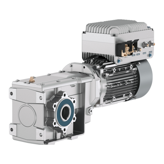
Page 27: Overview Of The Sinamics G115D Drive
The SINAMICS G115D decentralized drive is a compact drive designed to provide an adaptable solution to conveyor technology applications. The drive is a combination of a SINAMICS G115D converter and a SIMOGEAR geared motor and is available in the following two different variants: •... -
Page 28: Scope Of Delivery
2.2.1 SINAMICS G115D Motor Mounted The SINAMICS G115D converter with the SIMOGEAR geared motor constitutes the SINAMICS G115D Motor Mounted drive. The delivery comprises at least the following: • A ready-to-run drive with loaded firmware. The drive is delivered with the converter assembled with the geared motor. - Page 29 2.2 Scope of delivery Explanation on drive article number (example) Rating plate Rating plate for geared motors with SINAMICS G115D Motor Mounted (Page 367) Further information For more information about the SIMOGEAR geared motors, refer to the following chapter: Additional information on the SIMOGEAR geared motor (Page 353) SINAMICS G115D distributed drive Operating Instructions, 09/2020, FW V4.7 SP13, A5E48681219B...
-
Page 30: Sinamics G115D Wall Mounted
2.2.2 SINAMICS G115D Wall Mounted The SINAMICS G115D Wall Mounted drive is a combination of a G115D wall-mounted converter and a SIMOGEAR geared motor for G115D. The G115D wall-mounted converter and the 2KJ8 geared motor can only be ordered and delivered individually as drive system components. - Page 31 Overview of the SINAMICS G115D drive 2.2 Scope of delivery Explanation on article number (example) Article number of SIMOGEAR geared motor for G115D (2KJ8...) SINAMICS G115D distributed drive Operating Instructions, 09/2020, FW V4.7 SP13, A5E48681219B...
- Page 32 Overview of the SINAMICS G115D drive 2.2 Scope of delivery Article number of SINAMICS G115D wall-mounted converter (6SL352...) Rating plate The figure below shows an example of the rating plate attached to the side of the converter: ① Article number ③...
- Page 33 Compatible motors Siemens motors that can be operated You can connect SIMOGEAR 2KJ3 or 2KJ8 geared motors or other Siemens standard asynchronous or reluctance motors to the SINAMICS G115D wall-mounted converters. For further information on the possible SIMOGEAR geared motors in combination with the SINAMICS G115D converter, refer to the following: •...
-
Page 34: Directives And Standards
Overview of the SINAMICS G115D drive 2.3 Directives and standards Directives and standards The following directives and standards are relevant for the SINAMICS G115D converters and the configurable SIMOGEAR geared motors: European Low Voltage Directive The converters and motors fulfill the requirements stipulated in the Low-Voltage Directive 2014/35/EU, if they are covered by the application area of this directive. - Page 35 Internet: China RoHS (https://support.industry.siemens.com/cs/ww/en/view/109738656) Quality systems Siemens AG employs a quality management system that meets the requirements of ISO 9001 and ISO 14001. China Compulsory Certification The converters and motors do not fall in the area of validity of the China Compulsory Certification (CCC).
- Page 36 Overview of the SINAMICS G115D drive 2.3 Directives and standards SINAMICS G115D distributed drive Operating Instructions, 09/2020, FW V4.7 SP13, A5E48681219B...
-
Page 37: Mounting
• Transmission elements • Assembly conditions • Alignment and installation • Effects of external and internal vibrations SINAMICS G115D distributed drive Operating Instructions, 09/2020, FW V4.7 SP13, A5E48681219B... - Page 38 Note that the drive is delivered with the converter mounted on the geared motor. Mounting positions The SINAMICS G115D Motor Mounted drive supports mounting positions M1 to M6. You mount the drive based on the desired mounting configuration for the geared motor.
- Page 39 Maintain a minimum clearance distance of 150 mm (5.9 in) from the converter to the wall. For mounting clearance distance around the motor, refer to the following chapter: Installation conditions for the motor (Page 376) SINAMICS G115D distributed drive Operating Instructions, 09/2020, FW V4.7 SP13, A5E48681219B...
-
Page 40: Mounting The G115D Wall Mounted Drive
The permissible output current is reduced for mounting orientations ① ~ ④. ① Derating the output current to 80% of the rated converter current is necessary. ②③④ Derating the output current to 70% of the rated converter current is necessary. SINAMICS G115D distributed drive Operating Instructions, 09/2020, FW V4.7 SP13, A5E48681219B... - Page 41 425 (16.7) 180 (7.1) 169 (6.7) The glanded variant of the converter provides no cable gland when delivered. The dimension data of the cable glands is not provided here. SINAMICS G115D distributed drive Operating Instructions, 09/2020, FW V4.7 SP13, A5E48681219B...
- Page 42 168 (6.6) 410 (16.1) 5.5 (0.2) Mounting the motor The SINAMICS G115D wall-mounted converter supports SIMOGEAR geared motors, SIMOTICS motors, or third-party motors. For detailed information on installation of a SIMOGEAR geared motor, refer to the following documentation: • The relevant chapter in this manual Additional information on the SIMOGEAR geared motor (Page 353) •...
-
Page 43: Wiring
• Route particularly sensitive signal cables, such as setpoint and actual value cables, with optimum shield bonding at both ends and without any interruptions of the shield. • Ground spare wires for signal and data cables at both ends. SINAMICS G115D distributed drive Operating Instructions, 09/2020, FW V4.7 SP13, A5E48681219B... -
Page 44: Equipotential Bonding
(motor and driven machine) must be interconnected with respect to a high-frequency point of view. For this purpose cables with good high-frequency properties must be used. SINAMICS G115D distributed drive Operating Instructions, 09/2020, FW V4.7 SP13, A5E48681219B... - Page 45 Grounding and high-frequency equipotential bonding measures The following figure illustrates all grounding and high-frequency equipotential bonding measures using an example of the SINAMICS G115D Motor Mounted drive. The ground connections ① represent the conventional grounding system for the drive components. They are made with standard, heavy-power PE conductors without special high- frequency properties and ensure low frequency equipotential bonding as well as protection against injury.
-
Page 46: Permissible Line Supplies
IEC 60364-4-41:2005/AMD1:2017 Section 411 and Appendix D for protection against electric shock. • Observe the installation specifications provided in this manual. • Observe the applicable installation standards. • Ensure the continuity of the protective conductor. SINAMICS G115D distributed drive Operating Instructions, 09/2020, FW V4.7 SP13, A5E48681219B... -
Page 47: Tn Line System
In a TT system, the transformer grounding and the installation grounding are independent of one another. There are TT supplies where the neutral conductor N is either transferred – or not. SINAMICS G115D distributed drive Operating Instructions, 09/2020, FW V4.7 SP13, A5E48681219B... -
Page 48: Line System
If the grounding screw has been removed, the converter no longer fulfills the requirements of class More information on removing the grounding connection in the converter: Removing functional grounding of the converter (Page 47) SINAMICS G115D distributed drive Operating Instructions, 09/2020, FW V4.7 SP13, A5E48681219B... -
Page 49: Removing Functional Grounding Of The Converter
1. Release the retaining screws (6 x M4) for the Electronic Module by using a 3 mm allen key, and then remove the module. 2. Remove the functional grounding screw marked with the symbol from the back side of the Electronic Module. SINAMICS G115D distributed drive Operating Instructions, 09/2020, FW V4.7 SP13, A5E48681219B... -
Page 50: Requirements For The Protective Conductor
The drive components conduct a high leakage current via the protective conductor. Touching conductive parts when the protective conductor is interrupted can result in death or serious injury. • Comply with the requirements for the protective conductor. SINAMICS G115D distributed drive Operating Instructions, 09/2020, FW V4.7 SP13, A5E48681219B... - Page 51 Wiring 4.3 Requirements for the protective conductor Dimensioning the protective conductor The figure below takes the SINAMICS G115D Wall Mounted drive as an example. ① Protective conductor for mains supply cables ② Protective conductor for converter line supply cables ③...
-
Page 52: Requirements For Branch Circuit Protection
• A dedicated RCD is used for each converter. • Use a universal current-sensitive residual current protective device (RCD, RCM, ELCB or RCCB), type B, for example, Siemens SIQUENCE RCCB. Connect the RCCB in series with the overcurrent protective devices. -
Page 53: Forming Dc Link Capacitors
… Function description Procedure You form the DC link capacitors by supplying the converter with a line voltage of ≤ 100% of the rated voltage for a defined time. SINAMICS G115D distributed drive Operating Instructions, 09/2020, FW V4.7 SP13, A5E48681219B... -
Page 54: Overview Of The Converter Interfaces
Wiring Module and fix with the cable glands. Note that the converters of glanded variant provide no cable glands but blanking caps at delivery for all glanded interfaces. SINAMICS G115D distributed drive Operating Instructions, 09/2020, FW V4.7 SP13, A5E48681219B... - Page 55 Available on the wall-mounted converter only. The fan connector is designed for use in the wall-mounted converter FSB. The repair switch is available as an optional component of the wall-mounted converter. SINAMICS G115D distributed drive Operating Instructions, 09/2020, FW V4.7 SP13, A5E48681219B...
- Page 56 The electromechanical potentiometers and the repair switch on the converter do not provide protection against unauthorized access. You must take appropriate measures to protect the converter against unauthorized operation or changes to the settings. SINAMICS G115D distributed drive Operating Instructions, 09/2020, FW V4.7 SP13, A5E48681219B...
- Page 57 ⑦ Braking resistor terminals - DCP, PB DIO24, DIO25 ④ Switched/unswitched 24 V power supply ⑧ 180 V DC EM brake terminals - EM+, EM- terminals - 2L+, 2M / 1L+, 1M Protective earth SINAMICS G115D distributed drive Operating Instructions, 09/2020, FW V4.7 SP13, A5E48681219B...
- Page 58 Optional 400 V AC EM brake terminals (re- terminals - 2L+, 2M / 1L+, 1M served) - EM1, EM2 (for G115D Wall Mount- ed only) ⑤ DIP switches - DIP1, DIP2 Protective earth SINAMICS G115D distributed drive Operating Instructions, 09/2020, FW V4.7 SP13, A5E48681219B...
-
Page 59: Cables And Connectors
Cable, connectors and tools specifications The detailed specifications for the cables, connectors and tools required to manufacture the necessary cables for the SINAMICS G115D are listed in the following documents and can be accessed using the relevant link: Supplementary products (cables, connectors and accessories) (https://support.industry.siemens.com/cs/ww/en/view/65355810) -
Page 60: Maximum Permissible Cable Length
Shielded, coverage ≥ 85% 30 m (98 ft.) Maximum length for communication cables Communications protocol Transfer rate or cable type Max. length PROFINET CAT5e network cable 100 m (328 ft.) SINAMICS G115D distributed drive Operating Instructions, 09/2020, FW V4.7 SP13, A5E48681219B... -
Page 61: Cable Cross-Sections And Cable Lugs
(AWG 14 to AWG 10) EM+/EM- 2 × 0.75 mm to 4 mm (AWG 18 to AWG 12) T+/T- 2 × 0.75 mm to 1.5 mm (AWG 18 to AWG 16) SINAMICS G115D distributed drive Operating Instructions, 09/2020, FW V4.7 SP13, A5E48681219B... - Page 62 Frame size Terminal Cable lug Cross-section for stranded conductor Crimping type length FSA/FSB Spring-type Pin type 5 × 0.25 mm to 0.34 mm 8 mm (AWG 24 to AWG 22) SINAMICS G115D distributed drive Operating Instructions, 09/2020, FW V4.7 SP13, A5E48681219B...
- Page 63 1.5 to 2.5 16.3 M3.5 4 to 6 4 to 6 Pin type cable lug Cable cross-section (mm (mm) (mm) (mm) Crimping length l (mm) 0.75 16.5 18.5 18.5 19.5 SINAMICS G115D distributed drive Operating Instructions, 09/2020, FW V4.7 SP13, A5E48681219B...
-
Page 64: Connecting The Line Supply
Line phase L1 Line phase L2 Line phase L3 Protective earth Cable gland size: M25 * 1.5 Screw tightening torque: Screw tightening torque: 1.3 Nm/11.5 lbf.in 1.2 Nm/10.6 lbf.in SINAMICS G115D distributed drive Operating Instructions, 09/2020, FW V4.7 SP13, A5E48681219B... -
Page 65: Connecting To The Line Supply Using Daisy Chain
4.9.2 Connecting to the line supply using daisy chain The SINAMICS G115D system has been designed to allow a converter to provide the mains power for a number of converters in a daisy chain. The figure below exemplifies the methodology for daisy-chaining multiple converters:... - Page 66 For both connector and glanded variants, the input for the daisy chained converters can be protected by group fusing. For more information about the permissible types of the group fusing, see the SINAMICS G115D Product Information of Protective Devices: Protective devices (https://support.industry.siemens.com/cs/ww/en/ps/27867/man) SINAMICS G115D distributed drive Operating Instructions, 09/2020, FW V4.7 SP13, A5E48681219B...
-
Page 67: Connecting The Motor
Phase U Not connected Phase W EM brake negative (180 V DC) Motor temperature sensor positive EM brake positive (180 V DC) Phase V Motor temperature sensor negative Protective earth SINAMICS G115D distributed drive Operating Instructions, 09/2020, FW V4.7 SP13, A5E48681219B... -
Page 68: Connecting The Motor In A Star Or Delta Connection
The motor goes into field weakening above the rated frequency. In field weakening, the available motor torque decreases linearly with 1/f. In field weakening, the available power remains constant. SINAMICS G115D distributed drive Operating Instructions, 09/2020, FW V4.7 SP13, A5E48681219B... -
Page 69: Configuring The Star/Delta Connection Of The Wall-Mounted Converter
The star/delta connection is implemented inside the terminal box of the motor. You can configure the connection according to the circuit diagram of the motor. Star connection Delta connection SINAMICS G115D distributed drive Operating Instructions, 09/2020, FW V4.7 SP13, A5E48681219B... -
Page 70: Connecting The 24 V Power Supply
X01 - 24 V power supply X02 - 24 V power supply Signal Description (IN), 5-pin, male (OUT), 5-pin, female Unswitched 24 V Switched 0 V Unswitched 0 V Switched 24 V Not connected SINAMICS G115D distributed drive Operating Instructions, 09/2020, FW V4.7 SP13, A5E48681219B... - Page 71 For a complete explanation of the unswitched and switched 24 V supplies and their limitations, please read the FAQ at the following link: Unswitched and switched 24 V supply (https://support.industry.siemens.com/cs/ww/en/view/26986267) Further information Cables and connectors (Page 57) SINAMICS G115D distributed drive Operating Instructions, 09/2020, FW V4.7 SP13, A5E48681219B...
-
Page 72: Connecting To The 24 V Power Supply Using Daisy Chain
4.11.2 Connecting to the 24 V power supply using daisy chain The SINAMICS G115D system has been designed to allow a converter to provide the 24 V DC power for a number of converters in a daisy chain. The figure below exemplifies the methodology for daisy-chaining multiple converters:... -
Page 73: Connecting The Digital Inputs And Outputs
Digital input 3 Unswitched 0 V Digital input 2 Functional earth Signal Description Switched 24 V DIO25 Bidirectional digital output/input 25 Switched 0 V DIO24 Bidirectional digital output/input 24 Functional earth SINAMICS G115D distributed drive Operating Instructions, 09/2020, FW V4.7 SP13, A5E48681219B... - Page 74 If applicable, connect the digital inputs with suitably dimensioned, external resistors to protect against the reference potential of the digital inputs. Further information Cables and connectors (Page 57) SINAMICS G115D distributed drive Operating Instructions, 09/2020, FW V4.7 SP13, A5E48681219B...
-
Page 75: Factory Interface Setting
Only when commissioning do you define as to whether, for example, you use digital inputs for the standard functions, or you create a fail-safe digital input by combining them. SINAMICS G115D distributed drive Operating Instructions, 09/2020, FW V4.7 SP13, A5E48681219B... -
Page 76: Connecting To Profinet And Ethernet
Cables and connectors (Page 57) 4.13.2 Communication via PROFINET IO and Ethernet You can either integrate the converter in a PROFINET network or communicate with the converter via Ethernet. SINAMICS G115D distributed drive Operating Instructions, 09/2020, FW V4.7 SP13, A5E48681219B... - Page 77 PROFINET - the Ethernet standard for automation (http://w3.siemens.com/mcms/automation/en/industrial- communications/profinet/Pages/Default.aspx) Further information on the operation as Ethernet nodes can be found in the Function Manual "Fieldbuses". Overview of the manuals (Page 509) SINAMICS G115D distributed drive Operating Instructions, 09/2020, FW V4.7 SP13, A5E48681219B...
-
Page 78: Protocols Used
(PROFINET) PROFINET connection less RPC PROFINET Con- 34964 (4) UDP text Manager The PROFINET context manager provides an endpoint mapper in order to establish an application relationship (PROFINET AR). SINAMICS G115D distributed drive Operating Instructions, 09/2020, FW V4.7 SP13, A5E48681219B... -
Page 79: Connecting The Converter To Profinet
The maximum permitted cable length from the previous station and to the next one is 100 m. 2. Externally supply the converter with 24 V DC through interface X01. You have now connected the converter to the control system via PROFINET. ❒ SINAMICS G115D distributed drive Operating Instructions, 09/2020, FW V4.7 SP13, A5E48681219B... -
Page 80: What Do You Have To Set For Communication Via Profinet
PROFINET or PROFIBUS, with Safety Integrated (via terminal) and HMI (https://support.industry.siemens.com/cs/ww/en/view/60441457) Controlling the speed of a SINAMICS G110M/G120 (Startdrive) with S7-1500 (TO) via PROFINET or PROFIBUS, with Safety Integrated (via terminal) and HMI (https://support.industry.siemens.com/cs/ww/en/view/78788716) SINAMICS G115D distributed drive Operating Instructions, 09/2020, FW V4.7 SP13, A5E48681219B... -
Page 81: Installing Gsdml
Insert a memory card into the converter. Set p0804 = 12. The converter writes the GSDML as zipped file (*.zip) into directory /SIEMENS/SINAMICS/DATA/CFG on the memory card. 2. Unzip the GSDML file on your computer. 3. Import the GSDML into the engineering system of the controller. -
Page 82: What Do You Need For Communication Via Ethernet/Ip
Note: For the G115D Motor Mounted, use the PE terminal which is close to the motor drive end (DE) to ground the converter housing. Minimum cable cross-section: 4 mm (AWG 10) PE terminal tightening torque: 1.5 Nm (13.3 lbf.in) SINAMICS G115D distributed drive Operating Instructions, 09/2020, FW V4.7 SP13, A5E48681219B... -
Page 83: Connection Examples
Wiring 4.15 Connection examples 4.15 Connection examples Connection example for G115D Motor Mounted SINAMICS G115D distributed drive Operating Instructions, 09/2020, FW V4.7 SP13, A5E48681219B... - Page 84 Wiring 4.15 Connection examples Connection example for G115D Wall Mounted SINAMICS G115D distributed drive Operating Instructions, 09/2020, FW V4.7 SP13, A5E48681219B...
-
Page 85: Commissioning
(Page 101) 7. Save your settings and perform data backup. Saving the settings in the – converter (RAM → EEPROM) (Page 97) Data backup and series – commissioning (Page 281) SINAMICS G115D distributed drive Operating Instructions, 09/2020, FW V4.7 SP13, A5E48681219B... -
Page 86: Commissioning Tools
For the SINAMICS G115D Wall Mounted drive, the converter is pre-configured for an asynchronous motor that matches the rated power of the converter. For the SINAMICS G115D Motor Mounted drive, the converter has been set in the factory to the delivery condition to match the provided 2KJ8 geared motor. - Page 87 For a converter with PROFINET communication, the motor is operated in JOG mode via the fieldbus. When a control command is received, the motor rotates at ±150 rpm. The same ramp-up and ramp-down times as described above apply. SINAMICS G115D distributed drive Operating Instructions, 09/2020, FW V4.7 SP13, A5E48681219B...
-
Page 88: Collecting Motor Data
For more information about the detailed motor data, refer to the following section: Rating plate for geared motors with SINAMICS G115D Motor Mounted (Page 367) G115D wall-mounted converter... - Page 89 - North America NEMA: 60 Hz [hp] or 60 Hz [kW] • How is the motor connected? Pay attention to the connection of the motor (star connection [Y] or delta connection [Δ]). Note the appropriate motor data for connecting. SINAMICS G115D distributed drive Operating Instructions, 09/2020, FW V4.7 SP13, A5E48681219B...
-
Page 90: Selecting U/F Control Or Speed Control
• When you operate several motors on one converter. • When the maximum motor (4-pole) speed exceeds the following values: Converter pulse frequency 2 kHz 4 kHz and higher Maximum motor speed 4980 rpm 7200 rpm SINAMICS G115D distributed drive Operating Instructions, 09/2020, FW V4.7 SP13, A5E48681219B... -
Page 91: Quick Commissioning
Release the retaining screws (6 x M4 - 2.5 Nm) for the Electronic Module by using a 3 mm allen key, and then remove the module, as shown in the figure below: SINAMICS G115D distributed drive Operating Instructions, 09/2020, FW V4.7 SP13, A5E48681219B... - Page 92 DIP 1.4 Pulse frequency 16 kHz p1800 DIP 1.5 Motor type selection Reluctance motor p0300 DIP 1.6 87 Hz operation 87 Hz operation possible in a p0133 delta connection SINAMICS G115D distributed drive Operating Instructions, 09/2020, FW V4.7 SP13, A5E48681219B...
-
Page 93: Quick Commissioning With A Pc (Startdrive)
Creating a project Procedure 1. Start the Startdrive commissioning software. 2. Switch to project view by clicking on the link at the bottom left of the window, as shown below: SINAMICS G115D distributed drive Operating Instructions, 09/2020, FW V4.7 SP13, A5E48681219B... -
Page 94: Integrating The Converter Into The Project
5. When the USB interface is appropriately set, then the screen form shows the devices that can be accessed. SINAMICS G115D distributed drive Operating Instructions, 09/2020, FW V4.7 SP13, A5E48681219B... -
Page 95: Starting The Commissioning Wizard
2. In the following screen form, select the converter with which you wish to go online. 3. Once you are online, select the following command from the project tree: You have started the Commissioning Wizard of the converter. ❒ SINAMICS G115D distributed drive Operating Instructions, 09/2020, FW V4.7 SP13, A5E48681219B... -
Page 96: Carrying Out Quick Commissioning
– Enter the motor data according to the rating plate of your motor. – If you use a Siemens motor, select a motor based on its article number. In this case, the values of the selected motor are taken as default motor data. -
Page 97: Identifying Motor Data
In addition, based on the response of the rotating motor, the converter can determine a suitable setting for the vector control. To start the motor data identification routine, you must switch on the motor. SINAMICS G115D distributed drive Operating Instructions, 09/2020, FW V4.7 SP13, A5E48681219B... - Page 98 The converter starts the motor data identification. This measurement can take several minutes. Depending on the setting, after motor data identification has been completed, the converter switches off the motor - or it accelerates it to the currently set setpoint. SINAMICS G115D distributed drive Operating Instructions, 09/2020, FW V4.7 SP13, A5E48681219B...
-
Page 99: Saving The Settings In The Converter (Ram → Eeprom)
2. Select the command as follows from the project tree: 3. Click on the button in the dialog box as shown below: You have saved your settings retentively in the EEPROM. ❒ SINAMICS G115D distributed drive Operating Instructions, 09/2020, FW V4.7 SP13, A5E48681219B... -
Page 100: Restoring The Factory Settings
5.6.1 Restoring the factory settings/delivery condition (without safety functions) Procedure with Startdrive 1. Go online with the converter. 2. Select the command as follows from the project tree: SINAMICS G115D distributed drive Operating Instructions, 09/2020, FW V4.7 SP13, A5E48681219B... -
Page 101: Resetting The Safety Functions To The Factory Settings
❒ 5.6.2 Resetting the safety functions to the factory settings Procedure with Startdrive 1. Go online with the converter. 2. Select the command as follows from the project tree: SINAMICS G115D distributed drive Operating Instructions, 09/2020, FW V4.7 SP13, A5E48681219B... - Page 102 8. Switch off the converter power supply and wait until all LEDs on the converter are dark. 9. Switch on the converter power supply again. You have restored the safety functions in the converter to the factory settings. ❒ SINAMICS G115D distributed drive Operating Instructions, 09/2020, FW V4.7 SP13, A5E48681219B...
-
Page 103: Advanced Commissioning
Switching over the drive control (command data set) (Page 177) The converter can control a motor holding brake. The motor holding brake holds the motor in position when it is switched off. Motor holding brake (Page 179) SINAMICS G115D distributed drive Operating Instructions, 09/2020, FW V4.7 SP13, A5E48681219B... - Page 104 The protection functions prevent damage to the motor, converter and driven load. Overcurrent protection (Page 255) Converter protection using temperature monitoring (Page 256) Motor temperature monitoring using a temperature sensor (Page 259) SINAMICS G115D distributed drive Operating Instructions, 09/2020, FW V4.7 SP13, A5E48681219B...
-
Page 105: 6.2 Sequence Control When Switching The Motor On And Off
In order to be able to respond to external commands, you must set the command interface so that it fits your specific application. Tools To change the function settings, you can use a PC tool, for example. SINAMICS G115D distributed drive Operating Instructions, 09/2020, FW V4.7 SP13, A5E48681219B... - Page 106 The motor is considered to be stationary if the speed is less than a defined minimum speed. OFF2 The converter switches off the motor immediately without first braking it. Inhibit operation SINAMICS G115D distributed drive Operating Instructions, 09/2020, FW V4.7 SP13, A5E48681219B...
-
Page 107: Adapt The Default Settings Of The Inputs And Outputs
This chapter describes how you adapt the function of individual converter inputs and outputs using binectors and connectors. If parameterized as digital inputs via p0728 If parameterized as digital outputs via p0728 SINAMICS G115D distributed drive Operating Instructions, 09/2020, FW V4.7 SP13, A5E48681219B... -
Page 108: Digital Inputs
Example In order to switch on the motor with digital input DI 2, you have to connect the status parameter of DI 2 to p0840: Set p0840 = 722.2. SINAMICS G115D distributed drive Operating Instructions, 09/2020, FW V4.7 SP13, A5E48681219B... -
Page 109: Digital Outputs
You can invert the signal of the digital output using parameter p0748. For more information, see the parameter list and the function block diagram 2241 of the List Manual. SINAMICS G115D distributed drive Operating Instructions, 09/2020, FW V4.7 SP13, A5E48681219B... -
Page 110: Controlling Clockwise And Counter-Clockwise Rotation Via Digital Inputs
Three-wire control, method 2 Enable/OFF1: Enables the motor to be switched on or switched off Switches on the motor Reversing: Reverses the motor direction of rota- tion SINAMICS G115D distributed drive Operating Instructions, 09/2020, FW V4.7 SP13, A5E48681219B... -
Page 111: Two-Wire Control, Method 1
Changing the assignment of the digital inputs Parameter Description p0840[0…n] = 722.x BI: ON/OFF1 (ON/OFF1) Example: p0840 = 722.3 ⇒ DI 3: ON/OFF1 BI: Setpoint inversion (reversing) p1113[0…n] = 722.x 6.4.2 Two-wire control, method 2 SINAMICS G115D distributed drive Operating Instructions, 09/2020, FW V4.7 SP13, A5E48681219B... -
Page 112: Two-Wire Control, Method 3
ON/OFF1 clockwise ON/OFF1 counter- Function rotation clockwise rotation OFF1: The motor stops. ON: Clockwise motor rotation. ON: Counter-clockwise motor rotation. OFF1: The motor stops. SINAMICS G115D distributed drive Operating Instructions, 09/2020, FW V4.7 SP13, A5E48681219B... -
Page 113: Three-Wire Control, Method 1
… n] = 722.x p3332[0 … n] = 722.x BI: 2/3 wire control command 3 (ON counter-clockwise rotation) Example: p3332 = 722.0 ⇒ DI 0: ON counter-clockwise rotation SINAMICS G115D distributed drive Operating Instructions, 09/2020, FW V4.7 SP13, A5E48681219B... -
Page 114: Three-Wire Control, Method 2
Drive control via PROFINET 6.5.1 Receive data and send data Cyclic data exchange The converter receives cyclic data from the higher-level control and returns cyclic data to the control. SINAMICS G115D distributed drive Operating Instructions, 09/2020, FW V4.7 SP13, A5E48681219B... -
Page 115: Telegrams
6.5.2 Telegrams Telegrams that are available The user data of the telegrams that are available are described in the following. 16-bit speed setpoint SINAMICS G115D distributed drive Operating Instructions, 09/2020, FW V4.7 SP13, A5E48681219B... - Page 116 16-bit speed setpoint for PCS7 16-bit speed setpoint with reading and writing to parameters 16-bit speed setpoint for PCS7 with reading and writing to parameters Unassigned interconnection and length SINAMICS G115D distributed drive Operating Instructions, 09/2020, FW V4.7 SP13, A5E48681219B...
-
Page 117: Control And Status Word 1
1 = Do not disable RFG The ramp-function generator can be ena- bled. 0 = Stop RFG The output of the ramp-function generator p1141[0] = r2090.5 stops at the actual value. SINAMICS G115D distributed drive Operating Instructions, 09/2020, FW V4.7 SP13, A5E48681219B... - Page 118 It is only possible to switch on the motor p2080[6] = r0899.6 active after an OFF1 followed by ON. 1 = Alarm active Motor remains switched on; no acknowl- p2080[7] = r2139.7 edgement is necessary. SINAMICS G115D distributed drive Operating Instructions, 09/2020, FW V4.7 SP13, A5E48681219B...
-
Page 119: Control And Status Word 3
1 = DDS selection bit 1 p0821 = r2093.5 Not used Not used 1 = technology controller enable p2200[0] = r2093.8 1 = enable DC braking p1230[0] = r2093.9 10 Not used SINAMICS G115D distributed drive Operating Instructions, 09/2020, FW V4.7 SP13, A5E48681219B... - Page 120 Technology controller output ≦ p2292 at the lower limit 1 = technology controller output Technology controller output > p2291 at the upper limit Not used Not used Not used Not used SINAMICS G115D distributed drive Operating Instructions, 09/2020, FW V4.7 SP13, A5E48681219B...
-
Page 121: Control And Status Word G115D
LRC panel. 1 = Jog left active Motor Jogs to the left. p2084[13] = r8559.6 1 = Jog right active Motor Jogs to the right. p2084[14] = r8559.7 Not used SINAMICS G115D distributed drive Operating Instructions, 09/2020, FW V4.7 SP13, A5E48681219B... -
Page 122: Namur Message Word
You can find application examples relating to the parameter channel at the end of this section. AK: Request and response IDs Bits 12 … 15 of the 1st parameter channel word contain the request and response identifier SINAMICS G115D distributed drive Operating Instructions, 09/2020, FW V4.7 SP13, A5E48681219B... - Page 123 Lower or upper value limit exceeded (change request with a value outside the value limits) 03 hex Incorrect subindex (access to a subindex that does not exist) 04 hex No array (access with a subindex to non-indexed parameters) SINAMICS G115D distributed drive Operating Instructions, 09/2020, FW V4.7 SP13, A5E48681219B...
- Page 124 0000 … 1999 A0 hex 20000 … 21999 0000 … 1999 50 hex 30000 … 31999 0000 … 1999 F0 hex 60000 … 61999 0000 … 1999 74 hex SINAMICS G115D distributed drive Operating Instructions, 09/2020, FW V4.7 SP13, A5E48681219B...
- Page 125 • Because you want to read the parameter value, words 3 and 4 in the parameter channel for requesting the parameter value are irrelevant. They should be assigned a value of 0, for example. SINAMICS G115D distributed drive Operating Instructions, 09/2020, FW V4.7 SP13, A5E48681219B...
- Page 126 • PWE2, Bit 10 … 15: = 3F hex (drive object - 63 = 3F hex) • PWE2, Bit 0 … 9: = 2 hex (Index of Parameter (DI 2 = 2)) SINAMICS G115D distributed drive Operating Instructions, 09/2020, FW V4.7 SP13, A5E48681219B...
-
Page 127: Expanding Or Freely Interconnecting Telegrams
"Double word" format (p2061). If you set a specific telegram, or you change the telegram, then the converter automatically interconnects parameters p2051 and p2061 with the appropriate signals. Interconnection of the receive data SINAMICS G115D distributed drive Operating Instructions, 09/2020, FW V4.7 SP13, A5E48681219B... - Page 128 6. Check the telegram length for the received and sent words: – r2067[0] = 6 – r2067[1] = 6 You have expanded telegram 1 to 6 send words and 6 receive words. ❒ SINAMICS G115D distributed drive Operating Instructions, 09/2020, FW V4.7 SP13, A5E48681219B...
-
Page 129: Acyclically Reading And Writing Converter Parameters
2. The following parameters must match your Ethernet configuration: – p8921 = IP address – p8922 = default gateway – p8923 = subnet mask – p8920 = station name 3. p8925 = 2 SINAMICS G115D distributed drive Operating Instructions, 09/2020, FW V4.7 SP13, A5E48681219B... - Page 130 PN Default Gateway actual Displays the actual default gateway. r8933 PN Subnet Mask actual Displays the actual subnet mask. p8980 Ethernet/IP profile Sets the profile for Ethernet/IP. 0: SINAMICS 1: ODVA AC/DC SINAMICS G115D distributed drive Operating Instructions, 09/2020, FW V4.7 SP13, A5E48681219B...
- Page 131 For more information about the parameters, refer to the List Manual. Overview of the manuals (Page 509) Further information Ethernet/IP objects and assemblies of the converter: Supported objects (Page 130) SINAMICS G115D distributed drive Operating Instructions, 09/2020, FW V4.7 SP13, A5E48681219B...
-
Page 132: Supported Objects
• Get Attribute all • Get Attribute single • Get Attribute single • Reset Table 6- 1 Class Attribute Service Type Name UINT16 Revision UINT16 Max Instance UINT16 Num of Instances SINAMICS G115D distributed drive Operating Instructions, 09/2020, FW V4.7 SP13, A5E48681219B... - Page 133 8 … 11 Not used 12 … 15 Reserved Assembly Object, Instance Number: 4 hex Supported services Class Instance • Get Attribute single • Get Attribute single • Set Attribute single SINAMICS G115D distributed drive Operating Instructions, 09/2020, FW V4.7 SP13, A5E48681219B...
- Page 134 OpenFormat Rejects Counters UINT16 OpenResource Counters Rejects UINT16 OpenOther Rejects Counters UINT16 CloseReqs Counters UINT16 CloseFormat Rejects Counters UINT16 CloseOther Rejects Counters UINT16 ConnTimeouts Counters Number of bus errors SINAMICS G115D distributed drive Operating Instructions, 09/2020, FW V4.7 SP13, A5E48681219B...
- Page 135 Squirrel cage asynchronous motor 1PC1 asynchronous motor Non-standard motor 2KJ8 asynchronous motor Non-standard motor 1FP1 synchronous reluctance motor Non-standard motor 2KJ8 synchronous reluctance motor Non-standard motor 1FP3 synchronous reluctance motor Non-standard motor SINAMICS G115D distributed drive Operating Instructions, 09/2020, FW V4.7 SP13, A5E48681219B...
- Page 136 Fault reset STW.7 acknowledge fault UINT16 Fault Code r945[0] error code UINT16 Warning Code r2122[0] alarm code Bool CtlFromNet Display from Net Control 1: Control from network 0: Local control SINAMICS G115D distributed drive Operating Instructions, 09/2020, FW V4.7 SP13, A5E48681219B...
- Page 137 Vendor-specific mode 2 U/f with parabolic characteristic 4 U/f with linear characteristic and ECO 7 U/f for parabolic characteristic and ECO 20 Speed control (without encoder) Closed-loop speed control SINAMICS G115D distributed drive Operating Instructions, 09/2020, FW V4.7 SP13, A5E48681219B...
- Page 138 Advanced commissioning 6.6 Drive control via Ethernet/IP Siemens Drive Object, Instance Number: 32C hex Supported services Class Instance • Get Attribute single • Get Attribute single • Set Attribute single Table 6- 14 Class Attribute Service Type Name UINT16 Revision...
- Page 139 PID Feedback r2266 technology controller actual value after the filter REAL PID Output r2294 technology controller output signal Siemens Motor Data Object, Instance Number: 32D hex Supported services Class Instance • Get Attribute single • Get Attribute single • Set Attribute single SINAMICS G115D distributed drive Operating Instructions, 09/2020, FW V4.7 SP13, A5E48681219B...
- Page 140 Max Instance UINT16 Num of Instances Table 6- 19 Instance Attribute Service Type Name Value/explanation UNIT32 Status Fixed value: 1 hex 1: Configuration acknowledged, by DHCP or saved values SINAMICS G115D distributed drive Operating Instructions, 09/2020, FW V4.7 SP13, A5E48681219B...
- Page 141 Bit 1: Link-Status Bit 2: Duplex Mode (0: halb duplex, 1 duplex Bit 3 … 5: Automatic state identification Bit 6: Reset required Bit 7: Local hardware fault (0 = ok) SINAMICS G115D distributed drive Operating Instructions, 09/2020, FW V4.7 SP13, A5E48681219B...
- Page 142 Transmission unsuccessful as a result of an in- ternal MAC sublayer receive error. get, set Struct of Interface Control UINT16 Control Bits UINT16 Forced Interface Speed String Interface_Label Interface-Label SINAMICS G115D distributed drive Operating Instructions, 09/2020, FW V4.7 SP13, A5E48681219B...
-
Page 143: Supported Odva Ac/Dc Assemblies
• Data = 500.0 (value) 6.6.3 Supported ODVA AC/DC assemblies Overview Number Required/ Type Name optional 14 hex Required Sending Basic Speed Control Output 46 hex Required Receiving Basic Speed Control Input SINAMICS G115D distributed drive Operating Instructions, 09/2020, FW V4.7 SP13, A5E48681219B... -
Page 144: Creating Generic I/O Module
Overview For certain controllers, or if you wish to use the SINAMICS profile, you cannot use the EDS file provided by Siemens. In these cases, you must create a generic I/O module in the control system for the cyclic communication. -
Page 145: The Converter As Ethernet Node
You can find information about parameters and messages (A08565) in the List Manual. You can also integrate the converter into an Ethernet network by using Proneta or STEP 7. SINAMICS G115D distributed drive Operating Instructions, 09/2020, FW V4.7 SP13, A5E48681219B... -
Page 146: Jogging
In this case, the materials conveyed can always come to a standstill at the same point and be transferred or redirected without time or position deviation. SINAMICS G115D offers flexible and efficient solutions for the conveyor technology requirements of various horizontal or inclined applications in intralogistics, automotive, and airport industries. -
Page 147: Conveyors
• The motor stops with OFF1 ramp when the stop sensor positive direction (p3384) is triggered (level/edge triggered depending on p3394). • Setting the sensor bypass signal (p3390) to 1 overrides the stop sensor signal p3384. SINAMICS G115D distributed drive Operating Instructions, 09/2020, FW V4.7 SP13, A5E48681219B... - Page 148 You can commission the conveyor technology functions via the Startdrive PC tool. Note All screenshots in Chapter 6.8 "Conveyor technology control functions" take the converter with PROFINET interface as examples. SINAMICS G115D distributed drive Operating Instructions, 09/2020, FW V4.7 SP13, A5E48681219B...
-
Page 149: Conveyor, One Direction And Two Speeds (P3393 = 2)
• The motor stops with OFF1 ramp when the stop sensor positive direction (p3384) is triggered (level/edge triggered depending on p3394). • Setting the sensor bypass signal (p3390) to 1 overrides the sensor signals p3384 and p3387. SINAMICS G115D distributed drive Operating Instructions, 09/2020, FW V4.7 SP13, A5E48681219B... - Page 150 Advanced commissioning 6.8 Conveyor technology control functions Parameters Conveyor technology control parameters (Page 175) You can commission the conveyor technology functions via the Startdrive PC tool. SINAMICS G115D distributed drive Operating Instructions, 09/2020, FW V4.7 SP13, A5E48681219B...
-
Page 151: Conveyor, Two Directions And One Speed (P3393 = 3)
– No motor reaction is triggered by the stop sensor positive direction signal (p3384). • Setting the sensor bypass signal (p3390) to 1 overrides the sensor signals p3384 and p3385. SINAMICS G115D distributed drive Operating Instructions, 09/2020, FW V4.7 SP13, A5E48681219B... -
Page 152: Conveyor, Two Directions And Two Speeds (P3393 = 4)
Four sensors are required to signal the limit positions for the motor to stop or decelerate. SINAMICS G115D distributed drive Operating Instructions, 09/2020, FW V4.7 SP13, A5E48681219B... - Page 153 – No motor reaction is triggered by the stop sensor positive direction (p3384) and low speed sensor positive direction (p3387) signals. • Setting the sensor bypass signal (p3390) to 1 overrides the sensor signals p3384, p3385, p3387, and p3388. SINAMICS G115D distributed drive Operating Instructions, 09/2020, FW V4.7 SP13, A5E48681219B...
-
Page 154: Turntables
The turntable rotates from one end position to the other in the direction depending on the setting of the end position shutdown (p3392) and the polarity of the speed setpoint. SINAMICS G115D distributed drive Operating Instructions, 09/2020, FW V4.7 SP13, A5E48681219B... -
Page 155: Turntable, Two Positions And One Speed (P3393 = 5)
3 or 4 (edge triggering), a new ON command must be initiated to start the motor again in either positive or negative direction. – Setting the sensor bypass signal (p3390) to 1 overrides the sensor signals p3384 and p3385. SINAMICS G115D distributed drive Operating Instructions, 09/2020, FW V4.7 SP13, A5E48681219B... - Page 156 With the end position shutdown (p3392 = 1) and level-triggered sensor signals (p3394 = 1 or 2) activated, once a stop sensor is triggered, the motor stops even if the level is canceled. SINAMICS G115D distributed drive Operating Instructions, 09/2020, FW V4.7 SP13, A5E48681219B...
- Page 157 Advanced commissioning 6.8 Conveyor technology control functions Parameters Conveyor technology control parameters (Page 175) You can commission the conveyor technology functions via the Startdrive PC tool. SINAMICS G115D distributed drive Operating Instructions, 09/2020, FW V4.7 SP13, A5E48681219B...
-
Page 158: Turntable, Two Positions And Two Speeds (P3393 = 6)
– With the sensor evaluation type (p3394) set to 1 or 2 (level triggering), the motor starts again in either positive or negative direction when the level is canceled; with SINAMICS G115D distributed drive Operating Instructions, 09/2020, FW V4.7 SP13, A5E48681219B... - Page 159 = 1 or 2) activated, once a stop or low speed sensor is triggered, the motor stops or goes to low speed even if the level is canceled. SINAMICS G115D distributed drive Operating Instructions, 09/2020, FW V4.7 SP13, A5E48681219B...
- Page 160 Advanced commissioning 6.8 Conveyor technology control functions Parameters Conveyor technology control parameters (Page 175) You can commission the conveyor technology functions via the Startdrive PC tool. SINAMICS G115D distributed drive Operating Instructions, 09/2020, FW V4.7 SP13, A5E48681219B...
-
Page 161: Turntable, Three Positions And One Speed (P3393 = 7)
• With the end position shutdown activated (p3392 = 1), the following applies: – If the motor runs in positive direction, it stops only when the stop sensor center (p3386) or stop sensor positive direction (p3384) is triggered. SINAMICS G115D distributed drive Operating Instructions, 09/2020, FW V4.7 SP13, A5E48681219B... - Page 162 • Once a stop sensor at the positive or negative position is triggered, the motor stops even if the level is canceled. • Once a stop sensor at the center position is triggered, the motor stops; if the level is cancelled, then the motor runs again. SINAMICS G115D distributed drive Operating Instructions, 09/2020, FW V4.7 SP13, A5E48681219B...
- Page 163 Advanced commissioning 6.8 Conveyor technology control functions Parameters Conveyor technology control parameters (Page 175) You can commission the conveyor technology functions via the Startdrive PC tool. SINAMICS G115D distributed drive Operating Instructions, 09/2020, FW V4.7 SP13, A5E48681219B...
-
Page 164: Turntable, Three Positions And Two Speeds (P3393 = 8)
3 or 4 (edge triggering), a new ON command must be initiated to start the motor again in either positive or negative direction. SINAMICS G115D distributed drive Operating Instructions, 09/2020, FW V4.7 SP13, A5E48681219B... - Page 165 • Once a stop or low speed sensor at the center position is triggered, the motor stops and goes to low speed; if the level is cancelled, then the motor runs again. Parameters Conveyor technology control parameters (Page 175) SINAMICS G115D distributed drive Operating Instructions, 09/2020, FW V4.7 SP13, A5E48681219B...
- Page 166 Advanced commissioning 6.8 Conveyor technology control functions You can commission the conveyor technology functions via the Startdrive PC tool. SINAMICS G115D distributed drive Operating Instructions, 09/2020, FW V4.7 SP13, A5E48681219B...
-
Page 167: Corner Turntable Lifts
3 or 4 (edge triggering), a new ON command must be initiated to start the motor again in either positive or negative direction. – Setting the sensor bypass signal (p3390) to 1 overrides the sensor signals p3384 and p3385. SINAMICS G115D distributed drive Operating Instructions, 09/2020, FW V4.7 SP13, A5E48681219B... - Page 168 With the end position shutdown (p3392 = 1) and level-triggered sensor signals (p3394 = 1 or 2) activated, once a stop sensor is triggered, the motor stops even if the level is canceled. SINAMICS G115D distributed drive Operating Instructions, 09/2020, FW V4.7 SP13, A5E48681219B...
- Page 169 Advanced commissioning 6.8 Conveyor technology control functions Parameters Conveyor technology control parameters (Page 175) You can commission the conveyor technology functions via the Startdrive PC tool. SINAMICS G115D distributed drive Operating Instructions, 09/2020, FW V4.7 SP13, A5E48681219B...
-
Page 170: Corner Turntable Lift, Two Positions And Two Speeds (P3393 = 10)
3 or 4 (edge triggering), a new ON command must be initiated to start the motor again in either positive or negative direction. – Setting the sensor bypass signal (p3390) to 1 overrides the sensor signals p3384, p3385, p3387, and p3388. SINAMICS G115D distributed drive Operating Instructions, 09/2020, FW V4.7 SP13, A5E48681219B... - Page 171 Parameters Conveyor technology control parameters (Page 175) You can commission the conveyor technology functions via the Startdrive PC tool. SINAMICS G115D distributed drive Operating Instructions, 09/2020, FW V4.7 SP13, A5E48681219B...
-
Page 172: Travelling Trolleys
Three sensors are required to signal the limit positions for the motor to stop. SINAMICS G115D distributed drive Operating Instructions, 09/2020, FW V4.7 SP13, A5E48681219B... - Page 173 – Setting the sensor bypass signal (p3390) to 1 overrides the stop sensor center signal p3386. SINAMICS G115D distributed drive Operating Instructions, 09/2020, FW V4.7 SP13, A5E48681219B...
- Page 174 • Once a stop sensor at the center position is triggered, the motor stops; if the level is cancelled, then the motor runs again. Parameters Conveyor technology control parameters (Page 175) You can commission the conveyor technology functions via the Startdrive PC tool. SINAMICS G115D distributed drive Operating Instructions, 09/2020, FW V4.7 SP13, A5E48681219B...
-
Page 175: Travelling Trolley, Two Speeds (P3393 = 12)
• The end position shutdown must be activated with p3392 set to 1 to avoid damage to the devices. • The controlling PLC can activate/deactivate the sensor bypass signal (p3390) and define different positions among which the trolley can move. SINAMICS G115D distributed drive Operating Instructions, 09/2020, FW V4.7 SP13, A5E48681219B... - Page 176 • Once a stop or low speed sensor at the center position is triggered, the motor stops and goes to low speed; if the level is cancelled, then the motor runs again. SINAMICS G115D distributed drive Operating Instructions, 09/2020, FW V4.7 SP13, A5E48681219B...
-
Page 177: Conveyor Technology Control Parameters
Note that the supplementary setpoint adds to both p3397 and p3398 p1076[0...n] CI: Supplementary setpoint scaling Sets the signal source for scaling the supplemen- tary setpoint. Factory setting: 1 SINAMICS G115D distributed drive Operating Instructions, 09/2020, FW V4.7 SP13, A5E48681219B... - Page 178 CI: Rapid traverse setpoint signal Sets the signal source of the high speed setpoint. source The setpoint for the input is interconnected with the main setpoint p1070. SINAMICS G115D distributed drive Operating Instructions, 09/2020, FW V4.7 SP13, A5E48681219B...
-
Page 179: Switching Over The Drive Control (Command Data Set)
1. Set p0010 = 15. 2. The number of command data sets is configured with p0170. 3. Set p0010 = 0. You have changed the number of command data sets. ❒ SINAMICS G115D distributed drive Operating Instructions, 09/2020, FW V4.7 SP13, A5E48681219B... - Page 180 An overview of all the parameters that belong to the command data sets is provided in the List Manual. Note The converter requires approximately 4 ms to switch over the command data set. SINAMICS G115D distributed drive Operating Instructions, 09/2020, FW V4.7 SP13, A5E48681219B...
-
Page 181: Motor Holding Brake
When the "Motor holding brake" function is correctly set, the motor remains switched on as long as the motor holding brake is open. The converter only switches the motor off when the motor holding brake is closed. Function description SINAMICS G115D distributed drive Operating Instructions, 09/2020, FW V4.7 SP13, A5E48681219B... - Page 182 The motor holding brake must close within the time p1217. After the OFF2 command After the OFF2 command, the converter issues the signal to immediately close the motor holding brake, irrespective of the motor speed. SINAMICS G115D distributed drive Operating Instructions, 09/2020, FW V4.7 SP13, A5E48681219B...
- Page 183 – If the motor holding brake opens too late, the converter will accelerate the motor suddenly against the closed motor holding brake. Set p1216 larger. – If the motor waits too long before accelerating after the motor holding brake has opened, reduce p1216. SINAMICS G115D distributed drive Operating Instructions, 09/2020, FW V4.7 SP13, A5E48681219B...
- Page 184 Factory setting: 0.1 p1217 Motor holding brake closing time p1217 > braking signal relay runtimes + brake closing time Factory setting: 0.1 r0052.12 CO/BO: Status word 1: motor holding brake open SINAMICS G115D distributed drive Operating Instructions, 09/2020, FW V4.7 SP13, A5E48681219B...
-
Page 185: Free Function Block
• AND, OR, XOR, and NOT logic • RSR (RS flip-flop), DSR (D flip-flop) flip-flops • Timers MFP (pulse generator), PCL (pulse shortening), PDE (ON delay), PDF (OFF delay), and PST (pulse stretching) SINAMICS G115D distributed drive Operating Instructions, 09/2020, FW V4.7 SP13, A5E48681219B... -
Page 186: Selecting Physical Units
Rated motor torque lbf ft p0341 Motor moment of inertia lb ft p0344 Motor weight r0394 Rated motor power r1493 Total moment of inertia, scaled lb ft Factory setting SINAMICS G115D distributed drive Operating Instructions, 09/2020, FW V4.7 SP13, A5E48681219B... -
Page 187: System Of Units
For each parameter you can find the associated reference variable for scaling in the List Manual. Example: r0065 is scaled with reference variable p2000. If scaling is not specified in the List Manual, then the converter always represents/displays the parameter unscaled (not normalized). SINAMICS G115D distributed drive Operating Instructions, 09/2020, FW V4.7 SP13, A5E48681219B... -
Page 188: Technological Unit Of The Technology Controller
You must optimize the technology controller after changing p0595 or p0596. 6.12.4 Setting the system of units and technology unit Setting using Startdrive Precondition You are offline with Startdrive. SINAMICS G115D distributed drive Operating Instructions, 09/2020, FW V4.7 SP13, A5E48681219B... -
Page 189: Safe Torque Off (Sto) Safety Function
A converter with active STO function prevents energy supply to the motor. The motor can no longer generate torque at the motor shaft. Consequently, the STO function prevents the starting of an electrically-driven machine component. SINAMICS G115D distributed drive Operating Instructions, 09/2020, FW V4.7 SP13, A5E48681219B... - Page 190 ⇒ The STO converter function is in conformance to IEC/EN 61800-5-2. The distinction between Emergency Off and Emergency Stop "Emergency Off" and "Emergency Stop" are commands that minimize different risks in the machine or plant. SINAMICS G115D distributed drive Operating Instructions, 09/2020, FW V4.7 SP13, A5E48681219B...
- Page 191 A central emergency stop button must prevent the • Evaluate the Emergency Stop button in a unintentional acceleration of several motors that central control. are at a standstill. • Select STO via PROFIsafe. SINAMICS G115D distributed drive Operating Instructions, 09/2020, FW V4.7 SP13, A5E48681219B...
-
Page 192: Commissioning Sto
2. Load the project in the converter. After loading, the converter has the factory settings. 3. If a memory card inserted in the converter, remove it. 4. Recommission the converter. SINAMICS G115D distributed drive Operating Instructions, 09/2020, FW V4.7 SP13, A5E48681219B... -
Page 193: Configuring A Safety Function
Overview To ensure protection against unauthorized changes, it is recommended that you configure the safety function settings. Function description Procedure 1. Select "Select safety functionality". 2. Select "Basic Functions". SINAMICS G115D distributed drive Operating Instructions, 09/2020, FW V4.7 SP13, A5E48681219B... -
Page 194: Interconnecting The "Sto Active" Signal
2. Select the signal that matches your particular application. You have interconnected the "STO active" checkback signal. ❒ After STO has been selected, the converter signals "STO active" to the higher-level control. SINAMICS G115D distributed drive Operating Instructions, 09/2020, FW V4.7 SP13, A5E48681219B... -
Page 195: Setting The Filter For Fail-Safe Digital Inputs
The discrepancy time does not extend the converter response time. The converter selects its safety function as soon as one of the two F-DI signals changes its state from high to low. SINAMICS G115D distributed drive Operating Instructions, 09/2020, FW V4.7 SP13, A5E48681219B... - Page 196 A filter in the converter suppresses brief signals as a result of the bit pattern test or contact bounce. The filter extends the response time of the safety function by the debounce time. Setting the filter for fail-safe digital inputs Precondition You are online with Startdrive. SINAMICS G115D distributed drive Operating Instructions, 09/2020, FW V4.7 SP13, A5E48681219B...
-
Page 197: Setting The Forced Checking Procedure (Test Stop)
The forced checking procedure (test stop) of the basic functions is a converter self test. The converter checks its circuits to switch off the torque. Function description You start the forced checking procedure each time that the STO function is selected. SINAMICS G115D distributed drive Operating Instructions, 09/2020, FW V4.7 SP13, A5E48681219B... - Page 198 CO/BO: SI status (processor 1 + Signals for the higher-level control system. processor 2) Bit 31: Test stop is required for STO SINAMICS G115D distributed drive Operating Instructions, 09/2020, FW V4.7 SP13, A5E48681219B...
-
Page 199: Finalizing Online Commissioning
6. Switch off the converter power supply. 7. Wait until all LEDs on the converter go dark (no voltage condition). 8. Switch the converter power supply on again. Your settings are now active. ❒ SINAMICS G115D distributed drive Operating Instructions, 09/2020, FW V4.7 SP13, A5E48681219B... -
Page 200: Checking The Interconnection Of Digital Inputs
You can find a description of the CDS switchover in the operating instructions. You have ensured that the failsafe digital inputs only control the safety functions in the converter. ❒ SINAMICS G115D distributed drive Operating Instructions, 09/2020, FW V4.7 SP13, A5E48681219B... -
Page 201: Acceptance - Completion Of Commissioning
The following must be documented for the converter: • The results of the acceptance test. • The settings of the integrated drive safety functions. The documentation must be signed. SINAMICS G115D distributed drive Operating Instructions, 09/2020, FW V4.7 SP13, A5E48681219B... -
Page 202: Setpoints
• Check firmware versions 6.14 Setpoints 6.14.1 Overview The converter receives its main setpoint from the setpoint source. The main setpoint generally specifies the motor speed. SINAMICS G115D distributed drive Operating Instructions, 09/2020, FW V4.7 SP13, A5E48681219B... - Page 203 • When the technology controller is active and appropriately interconnected, its output specifies the motor speed. • When jogging is active. • When controlling from a Startdrive PC tool. SINAMICS G115D distributed drive Operating Instructions, 09/2020, FW V4.7 SP13, A5E48681219B...
-
Page 204: Specifying The Setpoint Via The Fieldbus
CI: Supplementary setpoint Signal source for the supplementary setpoint. Factory setting: 0 p1076[0...n] CI: Supplementary setpoint scaling Signal source for scaling the supplementary set- point. Factory setting: 0 SINAMICS G115D distributed drive Operating Instructions, 09/2020, FW V4.7 SP13, A5E48681219B... -
Page 205: Electromechanical Potentiometer
Interconnect the main setpoint with the internal analog inputs 0 and 1. p1070[1] = 755[1] Additional setpoint p1075[0] = 755[0] Interconnect the additional setpoint with the internal analog inputs 0 and 1. p1075[1] = 755[1] SINAMICS G115D distributed drive Operating Instructions, 09/2020, FW V4.7 SP13, A5E48681219B... -
Page 206: Motorized Potentiometer As Setpoint Source
"higher" and "lower" control signals. Function description Example Setting with the motorized potentiometer as setpoint source: Parameter Description p1070 = 1050 Interconnects the main setpoint with the motorized potentiometer output. SINAMICS G115D distributed drive Operating Instructions, 09/2020, FW V4.7 SP13, A5E48681219B... - Page 207 CI: Supplementary setpoint scaling Signal source for scaling the supplementary set- point Factory setting: 0 r1077 CO: Supplementary setpoint effec- Displays the effective supplementary setpoint. tive [rpm] The value shown is the additional setpoint after scaling. SINAMICS G115D distributed drive Operating Instructions, 09/2020, FW V4.7 SP13, A5E48681219B...
- Page 208 = 0 → 1. Factory setting: 0 p1044[0...n] CI: Motorized potentiometer, Signal source for the setting value setting value Factory setting: 0 SINAMICS G115D distributed drive Operating Instructions, 09/2020, FW V4.7 SP13, A5E48681219B...
-
Page 209: Fixed Speed Setpoint As Setpoint Source
Directly selecting a fixed speed setpoint p1020 p1021 p1022 p1023 Resulting setpoint p1001 p1002 p1001 + p1002 p1003 p1001 + p1003 p1002 + p1003 p1001 + p1002 + p1003 SINAMICS G115D distributed drive Operating Instructions, 09/2020, FW V4.7 SP13, A5E48681219B... - Page 210 + p1002 + p1003 + p1004 Selecting the fixed speed setpoint, binary p1020 p1021 p1022 p1023 Resulting setpoint p1001 p1002 p1003 p1004 p1005 p1006 p1007 p1008 p1009 p1010 p1011 p1012 p1013 p1014 p1015 SINAMICS G115D distributed drive Operating Instructions, 09/2020, FW V4.7 SP13, A5E48681219B...
- Page 211 Fixed speed setpoint selection mode Fixed speed setpoint mode Factory setting: 1 1: Direct 2: Binary p1020[0...n] Fixed speed setpoint selection, bit 0 Fixed speed setpoint selection, bit 0 Factory setting: 0 SINAMICS G115D distributed drive Operating Instructions, 09/2020, FW V4.7 SP13, A5E48681219B...
-
Page 212: Setpoint Processing
• The "Speed limitation" function protects the motor and the driven load against excessively high speeds. • The "Ramp-function generator" function prevents the setpoint from suddenly changing. As a consequence, the motor accelerates and brakes with a reduced torque. SINAMICS G115D distributed drive Operating Instructions, 09/2020, FW V4.7 SP13, A5E48681219B... -
Page 213: Invert Setpoint
Inverts the setpoint via the fieldbus (control word 1, bit 11). Parameters Parameter Description Setting p1113[0…n] BI: Setpoint inversion Sets the signal source to invert the setpoint. Factory setting: dependent upon the converter SINAMICS G115D distributed drive Operating Instructions, 09/2020, FW V4.7 SP13, A5E48681219B... -
Page 214: Inhibit Direction Of Rotation
Sets the signal source to disable the negative direction. Factory setting: 0 p1111[0…n] BI: Inhibit positive direction Sets the signal source to disable the positive di- rection. Factory setting: 0 SINAMICS G115D distributed drive Operating Instructions, 09/2020, FW V4.7 SP13, A5E48681219B... -
Page 215: Skip Frequency Bands And Minimum Speed
Factory setting: 1086 p1080[0...n] Minimum speed [rpm] Sets the lowest possible motor speed. Factory setting: 0 SINAMICS G115D distributed drive Operating Instructions, 09/2020, FW V4.7 SP13, A5E48681219B... -
Page 216: Speed Limitation
The converter generates a message (fault or alarm) when the maximum speed is exceeded. If you must limit the speed depending on the direction of rotation, then you can define speed limits for each direction. SINAMICS G115D distributed drive Operating Instructions, 09/2020, FW V4.7 SP13, A5E48681219B... -
Page 217: Ramp-Function Generator
(jerk) by rounding the setpoint. In this case, the torque does not rise suddenly in the motor. • Basic ramp-function generator The basic ramp-function generator limits the acceleration, however not the rate the acceleration changes (jerk). SINAMICS G115D distributed drive Operating Instructions, 09/2020, FW V4.7 SP13, A5E48681219B... - Page 218 The value applies to ramp-up and ramp-down. Factory setting: 0 p1131[0...n] Ramp-function generator, final Sets the final rounding-off time for the extended rounding-off time [s] ramp generator. Factory setting: 0 SINAMICS G115D distributed drive Operating Instructions, 09/2020, FW V4.7 SP13, A5E48681219B...
- Page 219 – Increase the initial rounding if the acceleration is jerky. – In most applications, it is sufficient when the final rounding is set to the same value as the initial rounding. 4. Switch off the motor. SINAMICS G115D distributed drive Operating Instructions, 09/2020, FW V4.7 SP13, A5E48681219B...
- Page 220 Ramp-function generator, ramp- The ramp-function generator ramps-up the speed up time [s] setpoint from standstill (setpoint = 0) up to the maximum speed (p1082) in this time. Factory setting: 1 SINAMICS G115D distributed drive Operating Instructions, 09/2020, FW V4.7 SP13, A5E48681219B...
- Page 221 Factory setting: 1 r2050[0...11] CO: PROFIdrive PZD receive word Connector output to interconnect PZD (setpoints) with word format received from the fieldbus con- troller. SINAMICS G115D distributed drive Operating Instructions, 09/2020, FW V4.7 SP13, A5E48681219B...
-
Page 222: Pid Technology Controller
To change the function settings, you can use a PC tool, for example. Function description Function diagram The technology controller is implemented as a PID controller (controller with proportional, integral, and differential action). SINAMICS G115D distributed drive Operating Instructions, 09/2020, FW V4.7 SP13, A5E48681219B... - Page 223 The settings required as a minimum are marked in gray in the function diagram: • Interconnect setpoint and actual values with signals of your choice • Set ramp-function generator and controller parameters K and T SINAMICS G115D distributed drive Operating Instructions, 09/2020, FW V4.7 SP13, A5E48681219B...
- Page 224 You must change this limit, depending on your particular application. Example: The output of the technology controller supplies the speed setpoint for a pump. The pump should only run in the positive direction. SINAMICS G115D distributed drive Operating Instructions, 09/2020, FW V4.7 SP13, A5E48681219B...
- Page 225 Technology controller differentia- Sets the time constant for the differentiation (D tion time constant [s] component) of the technology controller. Factory setting: 0 SINAMICS G115D distributed drive Operating Instructions, 09/2020, FW V4.7 SP13, A5E48681219B...
- Page 226 [%] ler. Factory setting: 0 p2293 Technology controller ramp- Sets the ramping time for the output signal of the up/ramp-down time [s] technology controller. Factory setting: 1 SINAMICS G115D distributed drive Operating Instructions, 09/2020, FW V4.7 SP13, A5E48681219B...
- Page 227 0: Output (y) = input (x) (factory setting) 1: Root function (root from x) 2: Square function (x * x) 3: Cube function (x * x * x) SINAMICS G115D distributed drive Operating Instructions, 09/2020, FW V4.7 SP13, A5E48681219B...
- Page 228 BI: Technology controller motor- Sets the signal source to continually increase the ized potentiometer, setpoint, raise setpoint for the motorized potentiometer of the technology controller. Factory setting: 0 SINAMICS G115D distributed drive Operating Instructions, 09/2020, FW V4.7 SP13, A5E48681219B...
- Page 229 • PID controller: Principle of operation of the D component, inhibiting the I component and the control sense • Enable, limiting the controller output and fault response FAQ (https://support.industry.siemens.com/cs/ww/en/view/92556266) SINAMICS G115D distributed drive Operating Instructions, 09/2020, FW V4.7 SP13, A5E48681219B...
-
Page 230: Motor Control
(flux current control, FCC) For operation of the motor with U/f control, you must set at least the following subfunctions appropriate for your application: • U/f characteristic • Voltage boost SINAMICS G115D distributed drive Operating Instructions, 09/2020, FW V4.7 SP13, A5E48681219B... -
Page 231: Characteristics Of U/F Control
The value of the output voltage at the rated motor frequency also depends on the following variables: • Ratio between the converter size and the motor size • Line voltage SINAMICS G115D distributed drive Operating Instructions, 09/2020, FW V4.7 SP13, A5E48681219B... -
Page 232: Selecting The U/F Characteristic
Additional information on U/f characteristics can be found in the parameter list and in the function diagrams of the List Manual. SINAMICS G115D distributed drive Operating Instructions, 09/2020, FW V4.7 SP13, A5E48681219B... -
Page 233: Optimizing Motor Starting
2. Check whether the motor rotates smoothly. 3. If the motor does not rotate smoothly, or even remains stationary, increase the voltage boost p1310 until the motor runs smoothly. SINAMICS G115D distributed drive Operating Instructions, 09/2020, FW V4.7 SP13, A5E48681219B... - Page 234 Factory setting: 0 Further information For further information refer to the parameter list and the function diagrams 6301 and 6310 of the List Manual. SINAMICS G115D distributed drive Operating Instructions, 09/2020, FW V4.7 SP13, A5E48681219B...
-
Page 235: Sensorless Vector Control With Speed Controller
I controllers keep the motor flux constant using the output voltage, and adjust the matching current component I in the motor. SINAMICS G115D distributed drive Operating Instructions, 09/2020, FW V4.7 SP13, A5E48681219B... - Page 236 • For pulling loads, carefully comply with the recommended settings for vector control. Advanced settings (Page 237) Further information For further information refer to the function diagrams 6040, 6050, and 6060 of the List Manual. SINAMICS G115D distributed drive Operating Instructions, 09/2020, FW V4.7 SP13, A5E48681219B...
-
Page 237: Optimizing The Closed-Loop Speed Controller
• The load moment of inertia is constant and independent of the speed. • The converter requires 10% … 50% of the rated torque to accelerate. When necessary, adapt the ramp-up and ramp-down times of the ramp-function generator (p1120 and p1121). SINAMICS G115D distributed drive Operating Instructions, 09/2020, FW V4.7 SP13, A5E48681219B... - Page 238 ): T ≥ 4 · p1452 • If, after these measures, the speed controller does not operate with an adequate dynamic performance, then increase p1470 (gain K ) step-by-step. SINAMICS G115D distributed drive Operating Instructions, 09/2020, FW V4.7 SP13, A5E48681219B...
-
Page 239: Advanced Settings
The droop function ensures even torque distribution between several mechanically coupled drives. The droop function reduces the speed setpoint as a function of the torque setpoint. SINAMICS G115D distributed drive Operating Instructions, 09/2020, FW V4.7 SP13, A5E48681219B... - Page 240 • Set the ramp-up and ramp-down times ≤ 10 s in the ramp-function generator. SINAMICS G115D distributed drive Operating Instructions, 09/2020, FW V4.7 SP13, A5E48681219B...
-
Page 241: Friction Characteristic
Precondition The motor is permitted to accelerate up to the rated speed without endangering persons or property. SINAMICS G115D distributed drive Operating Instructions, 09/2020, FW V4.7 SP13, A5E48681219B... - Page 242 0: Friction characteristic plot deactivated (factory setting) 1: Friction characteristic plot activated, both direc- tions 2: Friction characteristic plot activated, positive direction 3: Friction characteristic plot activated, negative direction SINAMICS G115D distributed drive Operating Instructions, 09/2020, FW V4.7 SP13, A5E48681219B...
-
Page 243: Moment Of Inertia Estimator
The speed controller corrects inaccuracies in the precontrol (feed-forward control). The more precise the value of the moment of inertia in the converter, the lower the overshoot after speed changes. SINAMICS G115D distributed drive Operating Instructions, 09/2020, FW V4.7 SP13, A5E48681219B... - Page 244 The calculation takes place under the following conditions: • Speed ≥ p1226 • Acceleration setpoint < 8 1/s (≙ speed change 480 rpm per s) • Acceleration × moment of inertia (r1493) < 0.9 × p1560 SINAMICS G115D distributed drive Operating Instructions, 09/2020, FW V4.7 SP13, A5E48681219B...
- Page 245 Moment of inertia precontrol is available for situations such as these. The moment of inertia precontrol assumes that there is an approximately linear relationship between the moment of inertia and the load torque. SINAMICS G115D distributed drive Operating Instructions, 09/2020, FW V4.7 SP13, A5E48681219B...
- Page 246 Drives with slip between the motor shaft and load are not permitted, e.g. as a result of loose or worn belts. If the conditions are not met, you must not activate the moment of inertia estimator. SINAMICS G115D distributed drive Operating Instructions, 09/2020, FW V4.7 SP13, A5E48681219B...
- Page 247 Sets the scaling for the acceleration precontrol of the ing [%] speed/velocity controller. According to rotating measurement of the motor data identification is p1496 = 100%. Factory setting: 0 SINAMICS G115D distributed drive Operating Instructions, 09/2020, FW V4.7 SP13, A5E48681219B...
- Page 248 Moment of inertia estimator Display and connector output for the monitored load load torque negative direc- torque in the negative direction of rotation. tion of rotation [Nm] Factory setting: 0 SINAMICS G115D distributed drive Operating Instructions, 09/2020, FW V4.7 SP13, A5E48681219B...
- Page 249 Sets the constant coefficients constant negative [kgm for moment of inertia pre- control in the negative direc- tion when the moment of inertia estimator is active. Factory setting: 0 SINAMICS G115D distributed drive Operating Instructions, 09/2020, FW V4.7 SP13, A5E48681219B...
-
Page 250: Pole Position Identification
The converter must measure the pole position for motors not equipped with an encoder, or for encoders, which do not supply the information regarding the pole position. If you are using a Siemens motor, then the converter automatically selects the appropriate technique to determine the pole position, and when required starts the pole position identification. -
Page 251: Torque Control
Prerequisites for the correct functioning of the torque control: • You have set the motor data correctly during the quick commissioning Quick commissioning (Page 89) • You have performed a motor data identification on the cold motor SINAMICS G115D distributed drive Operating Instructions, 09/2020, FW V4.7 SP13, A5E48681219B... -
Page 252: Electrically Braking The Motor
J of the motor and load and to the square of the speed n. The motor attempts to pass the energy on to the converter. SINAMICS G115D distributed drive Operating Instructions, 09/2020, FW V4.7 SP13, A5E48681219B... -
Page 253: Dc Braking
Function: 1. The motor speed has fallen below the starting speed. 2. The converter activates the DC braking as soon as the motor speed falls below the starting speed. SINAMICS G115D distributed drive Operating Instructions, 09/2020, FW V4.7 SP13, A5E48681219B... - Page 254 1. The higher-level control switches off the motor (OFF1 or OFF3). 2. The motor brakes along the down ramp to the speed for the start of DC braking. 3. DC braking starts. SINAMICS G115D distributed drive Operating Instructions, 09/2020, FW V4.7 SP13, A5E48681219B...
- Page 255 The converter's List Manual lists in the "Faults and alarms" list the possible fault responses for every fault. Entry "DCBRK" means that you may set DC braking as response for this fault. Factory setting: 0 SINAMICS G115D distributed drive Operating Instructions, 09/2020, FW V4.7 SP13, A5E48681219B...
-
Page 256: Dynamic Braking
Depending on the DC link voltage, the converter outputs the regenerative power to the integrated braking resistor. The built-in braking resistor converts the regenerative power into heat, therefore preventing DC link voltages > Vdc_max. SINAMICS G115D distributed drive Operating Instructions, 09/2020, FW V4.7 SP13, A5E48681219B... -
Page 257: Overcurrent Protection
I_max controller reduces the speed and the motor voltage until the motor current returns to the permissible range again. If the motor current reaches the current limit during deceleration, the I_max controller extends the deceleration operation. SINAMICS G115D distributed drive Operating Instructions, 09/2020, FW V4.7 SP13, A5E48681219B... -
Page 258: Converter Protection Using Temperature Monitoring
(alarm A07805, fault F30005) • Measuring the chip temperature of the converter (alarm A05006, fault F30024) • Measuring the heat sink temperature of the converter (alarm A05000, fault F30004) SINAMICS G115D distributed drive Operating Instructions, 09/2020, FW V4.7 SP13, A5E48681219B... - Page 259 Overload response for p0290 = 3 If you operate the converter with increased pulse frequency, then the converter reduces its pulse frequency starting at the pulse frequency setpoint p1800. SINAMICS G115D distributed drive Operating Instructions, 09/2020, FW V4.7 SP13, A5E48681219B...
- Page 260 If it is not possible to temporarily reduce the pulse frequency, or the measure cannot prevent a power unit thermal overload, then the converter switches off the motor with fault F30024. SINAMICS G115D distributed drive Operating Instructions, 09/2020, FW V4.7 SP13, A5E48681219B...
-
Page 261: Motor Temperature Monitoring Using A Temperature Sensor
• Pt1000 Sensor Connect the motor's temperature sensor through the motor output cable on the converter. For more information about motor interface, see Interface description - X2 (Page 65). SINAMICS G115D distributed drive Operating Instructions, 09/2020, FW V4.7 SP13, A5E48681219B... - Page 262 The converter interprets a resistance < 20 Ω as being a short-circuit and responds with alarm A07015. If the alarm is present for longer than 100 milliseconds, the converter shuts down with fault F07016. SINAMICS G115D distributed drive Operating Instructions, 09/2020, FW V4.7 SP13, A5E48681219B...
- Page 263 2 or KTY/Pt1000. Factory setting: 130 p0605[0...n] Mot_temp_mod 1/2/sensor Sets the threshold and temperature value to monitor threshold and temperature the motor temperature. value [°C] Factory setting: 145 SINAMICS G115D distributed drive Operating Instructions, 09/2020, FW V4.7 SP13, A5E48681219B...
-
Page 264: Motor Protection By Calculating The Temperature
The thermal motor model 2 for asynchronous motors is a thermal 3-mass model, consisting of stator core, stator winding and rotor. Thermal motor model 2 calculates the temperatures - both in the rotor as well as in the stator winding. SINAMICS G115D distributed drive Operating Instructions, 09/2020, FW V4.7 SP13, A5E48681219B... - Page 265 Displays the stator winding temperature of the motor ing temperature [°C] temperature model. p0640[0...n] Current limit [A] Sets the current limit. Factory setting: 0 Further information is provided in the parameter list. SINAMICS G115D distributed drive Operating Instructions, 09/2020, FW V4.7 SP13, A5E48681219B...
-
Page 266: Motor And Converter Protection By Limiting The Voltage
The Vdc_max control is not suitable for applications where the motor is in continuous regenerative operation, e.g. as is the case for cranes and centrifuges. Electrically braking the motor (Page 250) SINAMICS G115D distributed drive Operating Instructions, 09/2020, FW V4.7 SP13, A5E48681219B... -
Page 267: Monitoring The Driven Load
An insufficient motor current indicates that the motor cable is disconnected. If the motor current for the time p2180 lies below the current level p2179, the converter signals the alarm A07929. SINAMICS G115D distributed drive Operating Instructions, 09/2020, FW V4.7 SP13, A5E48681219B... -
Page 268: Rotation Monitoring
BI: Load monitoring, failure Sets the signal source for detecting a failure. detection Factory setting: 1 For more information, see the List Manual (the parameter list and function diagram 8013). SINAMICS G115D distributed drive Operating Instructions, 09/2020, FW V4.7 SP13, A5E48681219B... -
Page 269: Torque Monitoring
2. Set the speed thresholds p2182 … p2184 to the respective values. 3. Set the torque thresholds for each speed. The converter displays the current torque in r0031. 4. Set p2193 = 1. You have now set monitoring. ❒ SINAMICS G115D distributed drive Operating Instructions, 09/2020, FW V4.7 SP13, A5E48681219B... - Page 270 Load monitoring configuration Sets the load monitoring configuration: 0: Monitoring switched off 1: Monitoring torque and load drop (factory set- ting) 2: Monitoring speed and load drop 3: Load failure monitoring SINAMICS G115D distributed drive Operating Instructions, 09/2020, FW V4.7 SP13, A5E48681219B...
-
Page 271: Blocking Protection, Leakage Protection And Dry-Running Protection
The monitoring is not active below speed threshold 1 and above speed threshold 3. When using the control mode "U/f control" (p1300 < 10), the "Blocking protection" function becomes active when the current limit is reached. No-load monitoring (Page 265) SINAMICS G115D distributed drive Operating Instructions, 09/2020, FW V4.7 SP13, A5E48681219B... - Page 272 The converter displays the current torque in r0031. You have now set monitoring. ❒ Setting fan and compressor monitoring 1. Set p2193 = 5. 2. The converter sets the monitoring as shown. SINAMICS G115D distributed drive Operating Instructions, 09/2020, FW V4.7 SP13, A5E48681219B...
- Page 273 Sets the response when evaluating the load moni- toring. 0: Load monitoring disabled (factory setting) 7: Pump/fan load monitoring as alarm (A07891, A07892, A07893) 8: Pump/fan load monitoring as fault (F07894, F07895, F07896) SINAMICS G115D distributed drive Operating Instructions, 09/2020, FW V4.7 SP13, A5E48681219B...
- Page 274 4: Monitoring pump and load failure 5: Monitoring fan and load failure Further information If you deselect monitoring with p2193 < 4, the converter then resets the load monitoring parameters to factory settings. SINAMICS G115D distributed drive Operating Instructions, 09/2020, FW V4.7 SP13, A5E48681219B...
-
Page 275: Efficiency Optimization
However, in all applications, speed and torque are specified by the driven machine. As a consequence, the remaining variable for the efficiency optimization is the flux. The converter has two different methods of optimizing the efficiency. SINAMICS G115D distributed drive Operating Instructions, 09/2020, FW V4.7 SP13, A5E48681219B... - Page 276 The motor operates in partial load mode between no-load operation and the rated motor torque. Depending on p1580, in the partial load range, the converter reduces the flux setpoint linearly with the torque. SINAMICS G115D distributed drive Operating Instructions, 09/2020, FW V4.7 SP13, A5E48681219B...
- Page 277 0 %: Efficiency optimization is deactivated. 100 %: In no-load operation, the converter reduc- es the flux setpoint to 50% of the rated motor flux. The factory setting depends on the converter. SINAMICS G115D distributed drive Operating Instructions, 09/2020, FW V4.7 SP13, A5E48681219B...
-
Page 278: Calculating The Energy Saving For Fluid Flow Machines
The calculation is suitable for centrifugal pumps, fans, radial and axial compressors, for in- stance. SINAMICS G115D distributed drive Operating Instructions, 09/2020, FW V4.7 SP13, A5E48681219B... - Page 279 Specifies the power (P) of point 2 as a [%]. Factory setting: 50 p3323[0…n] Fluid flow machine speed, point 2 Specifies the speed (n) of point 2 as a [%]. Factory setting: 25 SINAMICS G115D distributed drive Operating Instructions, 09/2020, FW V4.7 SP13, A5E48681219B...
-
Page 280: Switchover Between Different Settings
The associated parameters are indexed (index 0, 1, 2, or 3). One of the four indexes is selected with control commands, and thereby one of the four saved settings. The settings in the converter with the same index are called the drive data set. SINAMICS G115D distributed drive Operating Instructions, 09/2020, FW V4.7 SP13, A5E48681219B... - Page 281 = 1, 2, 3 or 4 Factory setting: 1 p0819[0…2] Copy drive data set DDS [0] Source Drive Data Set [1] Target Drive Data Set [2] 0→1: Starts the copy operation Factory setting: 0 SINAMICS G115D distributed drive Operating Instructions, 09/2020, FW V4.7 SP13, A5E48681219B...
- Page 282 Factory setting: 0 Further information The converter switches the motor data set (MDS) and the power unit data set (PDS) together with the drive data set (DDS). SINAMICS G115D distributed drive Operating Instructions, 09/2020, FW V4.7 SP13, A5E48681219B...
-
Page 283: Data Backup And Series Commissioning
Transferring settings using a memory card 7.1.1 Memory cards Recommended memory cards Scope of delivery Article number Memory card without firmware 6SL3054-4AG00-2AA0 Memory card with firmware V4.7 SP13 6SL3054-7TG00-2BA0 SINAMICS G115D distributed drive Operating Instructions, 09/2020, FW V4.7 SP13, A5E48681219B... - Page 284 Inserting a memory card You may find the memory card slot on the G115D Wiring Module. See the following images for the detailed location: SINAMICS G115D converter with SIMOGEAR geared motor SINAMICS G115D wall-mounted converter Note For more information about performing a converter firmware upgrade and downgrade by...
-
Page 285: Converter → Memory Card
The following functions are either not possible – or only with some restrictions – when using memory cards from other manufacturers: • Know-how protection is only possible with one of the recommended Siemens memory cards. • Under certain circumstances, memory cards from other manufacturers do not support writing or reading data from/to the converter. - Page 286 2. Proceed as follows to transfer converter settings to the memory card. 3. Wait until Startdrive reports that data backup has been completed. You have backed up the converter settings to the memory card. ❒ SINAMICS G115D distributed drive Operating Instructions, 09/2020, FW V4.7 SP13, A5E48681219B...
-
Page 287: Memory Card → Converter
3. Wait until Startdrive has signaled that the data transfer has been completed. Note After the transferring process has completed, safely remove the memory card. You have transferred your settings from a memory card to the converter. ❒ SINAMICS G115D distributed drive Operating Instructions, 09/2020, FW V4.7 SP13, A5E48681219B... -
Page 288: Activating Message For A Memory Card That Is Not Inserted
Displays the status of the memory card. card status Bit 00: Memory card inserted Bit 01: Memory card activated Bit 02: Siemens memory card Bit 03: Memory card used as USB data storage medium from the PC SINAMICS G115D distributed drive... -
Page 289: Transferring Settings Using A Pg/Pc
2. Proceed as follows to transfer settings from the converter to the PG/PC: 3. Wait until Startdrive prompts that the transfer procedure is complete. You have transferred the settings from the converter to the PG/PC with Startdrive. ❒ SINAMICS G115D distributed drive Operating Instructions, 09/2020, FW V4.7 SP13, A5E48681219B... -
Page 290: Pg/Pc → Converter
2. Proceed as follows to transfer settings from the PG/PC to the converter: 3. Wait until Startdrive prompts that the transfer procedure is complete. 4. Go offline. You have transferred the settings from the PG/PC to the converter with Startdrive. ❒ SINAMICS G115D distributed drive Operating Instructions, 09/2020, FW V4.7 SP13, A5E48681219B... -
Page 291: Other Ways To Back Up Settings
On the memory card, you can back up 99 other settings in addition to the default setting. Additional information is available on the Internet: Memory options (http://support.automation.siemens.com/WW/view/en/43512514) SINAMICS G115D distributed drive Operating Instructions, 09/2020, FW V4.7 SP13, A5E48681219B... -
Page 292: Write Protection
Master control mode selection Sets the mode to change over the master control / LOCAL mode. p7761 Write protection Setting for activating/deactivating the write pro- tection for adjustable parameters. SINAMICS G115D distributed drive Operating Instructions, 09/2020, FW V4.7 SP13, A5E48681219B... -
Page 293: Know-How Protection
The converter can be operated with or without memory card. Know-how protection with basic copy protection The converter can only be operat- ed with a Siemens memory card. Know-how protection with extended copy protec- tion Memory cards (Page 281) SINAMICS G115D distributed drive... - Page 294 After replacing a converter, to be able to operate the new converter with the settings of the replaced converter without knowing the password, the memory card must be inserted in the new converter. SINAMICS G115D distributed drive Operating Instructions, 09/2020, FW V4.7 SP13, A5E48681219B...
-
Page 295: Extending The Exception List For Know-How Protection
KHP OEM exception list Sets parameters that should be excluded from know-how protection. Factory setting [0] 7766, [1 …499 ] 0 p7766[0...29] KHP password input Sets the password for know-how protection. SINAMICS G115D distributed drive Operating Instructions, 09/2020, FW V4.7 SP13, A5E48681219B... -
Page 296: Activating And Deactivating Know-How Protection
Bit 03: Know-how protection cannot be deactivated Bit 04: Extended copy protection active Bit 05: Basic copy protection active Bit 06: Trace and measurement functions for diagnostic purposes active SINAMICS G115D distributed drive Operating Instructions, 09/2020, FW V4.7 SP13, A5E48681219B... - Page 297 For memory cards that have already been written to, previously backed up data that was not encrypted can be reconstructed. SINAMICS G115D distributed drive Operating Instructions, 09/2020, FW V4.7 SP13, A5E48681219B...
- Page 298 Data backup and series commissioning 7.5 Know-how protection SINAMICS G115D distributed drive Operating Instructions, 09/2020, FW V4.7 SP13, A5E48681219B...
-
Page 299: Alarms, Faults And System Messages
A G115D converter has a number of LEDs which are designed to indicate the operational state of the converter. The LEDs are used to indicate the following states: • General fault conditions • Communication status • Safety-Integrated status • Input and output status SINAMICS G115D distributed drive Operating Instructions, 09/2020, FW V4.7 SP13, A5E48681219B... - Page 300 Please contact Technical Support for LED states that are not described in the following. Basic states Explanation Temporary state after the supply voltage is switched on The converter is free of faults SINAMICS G115D distributed drive Operating Instructions, 09/2020, FW V4.7 SP13, A5E48681219B...
- Page 301 One or more safety functions are enabled, but not active One or more safety functions are active and error-free The converter has detected a safety function fault and initiated a stop response SINAMICS G115D distributed drive Operating Instructions, 09/2020, FW V4.7 SP13, A5E48681219B...
-
Page 302: System Runtime
Parameter Description Setting r2114[0...1] Total system runtime Displays the total system runtime for the drive unit. Index: [0]: Milliseconds [1]: Days You cannot reset the system runtime. SINAMICS G115D distributed drive Operating Instructions, 09/2020, FW V4.7 SP13, A5E48681219B... -
Page 303: Identification & Maintenance Data (I&M)
0001 hex ✓ SOFTWARE_REVISION char, u8[3] „V“ 04.70.19 ✓ REVISION_COUNTER 0000 hex ✓ PROFILE_ID 3A00 hex ✓ PROFILE_SPECIFIC_TYPE 0000 hex ✓ IM_VERSION u8[2] 01.02 ✓ IM_SUPPORTED bit[16] 001E hex ✓ SINAMICS G115D distributed drive Operating Instructions, 09/2020, FW V4.7 SP13, A5E48681219B... -
Page 304: Alarms, Alarm Buffer, And Alarm History
In the alarm buffer, the warnings are sorted according to "Warning time received". If the alarm buffer is completely filled and an additional alarm occurs, then the converter overwrites the values with Index [7]. SINAMICS G115D distributed drive Operating Instructions, 09/2020, FW V4.7 SP13, A5E48681219B... - Page 305 4. The converter saves the received alarm as the latest alarm in the alarm buffer. The alarm history saves up to 56 alarms. In the alarm history, alarms are sorted according to the "alarm time received". The latest alarm has Index [8]. SINAMICS G115D distributed drive Operating Instructions, 09/2020, FW V4.7 SP13, A5E48681219B...
- Page 306 1: Fault 2: Alarm 3: No message Factory setting: 1 For more information about this function, see function diagram 8075 and parameter description in the List Manual. SINAMICS G115D distributed drive Operating Instructions, 09/2020, FW V4.7 SP13, A5E48681219B...
-
Page 307: Faults, Fault Buffer And Fault History
• Fault time removed = r2136 + r2109 The converter takes its internal time calculation to save the fault times. System runtime (Page 300) Up to 8 faults can be saved in the fault buffer. SINAMICS G115D distributed drive Operating Instructions, 09/2020, FW V4.7 SP13, A5E48681219B... - Page 308 The "Fault time removed" of the faults that have not been removed retains the value = 0. The fault history can contain up to 56 faults. Deleting the fault history To delete all faults from the fault history, set parameter p0952 = 0. SINAMICS G115D distributed drive Operating Instructions, 09/2020, FW V4.7 SP13, A5E48681219B...
- Page 309 Factory setting: 0 p2119[0 … 19] Changing message type, Sets the message type for the selected fault or type alarm. 1: Fault 2: Alarm 3: No message Factory setting: 1 SINAMICS G115D distributed drive Operating Instructions, 09/2020, FW V4.7 SP13, A5E48681219B...
-
Page 310: List Of Alarms And Faults
Check the module parameters and recommission if necessary. F01033 Unit switchover: Reference param- Set the value of the reference parameter not equal to 0.0 (p0304, p0305, eter value invalid p0310, p0596, p2000, p2001, p2002, p2003, r2004). SINAMICS G115D distributed drive Operating Instructions, 09/2020, FW V4.7 SP13, A5E48681219B... - Page 311 Check the parameterized supply voltage and if required change (p0210). parameterized Check the line voltage. F07011 Motor overtemperature Reduce the motor load. Check ambient temperature. Check the wiring and connection of the sensor. SINAMICS G115D distributed drive Operating Instructions, 09/2020, FW V4.7 SP13, A5E48681219B...
- Page 312 Check motor and motor cables for short circuit and ground fault. Check motor for star-delta connection and rating plate parameterization. Check power unit / motor combination. Select flying restart function (p1200) if switched to rotating motor. SINAMICS G115D distributed drive Operating Instructions, 09/2020, FW V4.7 SP13, A5E48681219B...
- Page 313 If the error occurs repeatedly, check the set monitoring time p2044. F08502 Monitoring time sign-of-life expired • Check the PROFINET connection. A08511 Receive configuration data not • Check the PROFINET configuration valid SINAMICS G115D distributed drive Operating Instructions, 09/2020, FW V4.7 SP13, A5E48681219B...
- Page 314 Check the rated currents of the motor and Power Module. Reduce current limit p0640. When operating with U/f characteristic: Reduce p1341. F30011 Line phase failure Check the converter's input fuses. Check the line cables. SINAMICS G115D distributed drive Operating Instructions, 09/2020, FW V4.7 SP13, A5E48681219B...
- Page 315 Software fault in Power Module Replace Power Module or contact technical support. A30920 Temperature sensor fault Check that the sensor is connected correctly. For details, please refer to the List Manual. SINAMICS G115D distributed drive Operating Instructions, 09/2020, FW V4.7 SP13, A5E48681219B...
- Page 316 Alarms, faults and system messages 8.6 List of alarms and faults SINAMICS G115D distributed drive Operating Instructions, 09/2020, FW V4.7 SP13, A5E48681219B...
-
Page 317: Corrective Maintenance
• Only commission the following persons to repair the converter: – Siemens customer service – A repair center that has been authorized by Siemens – Specialist personnel who are thoroughly acquainted with all the warnings and operating procedures contained in this manual. -
Page 318: Replacing The Converter
Unexpected machine motion can result in death, injury or material damage. • In all cases not permitted according to the above requirement, you must recommission the drive after replacing the converter. SINAMICS G115D distributed drive Operating Instructions, 09/2020, FW V4.7 SP13, A5E48681219B... - Page 319 An incorrect direction of rotation can lead to damage in the machine or system. • Connect the three phases of the motor lines in the right order. SINAMICS G115D distributed drive Operating Instructions, 09/2020, FW V4.7 SP13, A5E48681219B...
-
Page 320: Replacing A Converter With Active Know-How Protection
To avoid the recommissioning, there are two options for replacing the converter. Precondition • The end customer must use a Siemens memory card • The machine manufacturer must have an identical prototype machine that it uses as sample SINAMICS G115D distributed drive Operating Instructions, 09/2020, FW V4.7 SP13, A5E48681219B... - Page 321 Activating and deactivating know-how protection (Page 294) – Enter the serial number of the new converter in p7759. – Enter the serial number of the customer's memory card as reference serial number in p7769. SINAMICS G115D distributed drive Operating Instructions, 09/2020, FW V4.7 SP13, A5E48681219B...
-
Page 322: Repair Switch
– Send the encrypted project to the end customer, e.g. via e-mail. 3. The end customer copies the project to the Siemens memory card that belongs to the machine, inserts it in the converter and switches on the power supply of the converter. -
Page 323: Firmware Upgrade And Downgrade
The converter can be damaged if the power supply is interrupted during firmware upgrade or downgrade. • Ensure that the power supply is stable before starting the firmware upgrade or downgrade. SINAMICS G115D distributed drive Operating Instructions, 09/2020, FW V4.7 SP13, A5E48681219B... - Page 324 Corrective maintenance 9.4 Firmware upgrade and downgrade Overview User actions Converter response SINAMICS G115D distributed drive Operating Instructions, 09/2020, FW V4.7 SP13, A5E48681219B...
-
Page 325: Preparing The Memory Card
You have prepared the memory card for the firmware upgrade or downgrade. ❒ 9.4.2 Upgrading the firmware Overview When upgrading the firmware, you replace the converter firmware with a newer version. SINAMICS G115D distributed drive Operating Instructions, 09/2020, FW V4.7 SP13, A5E48681219B... - Page 326 The transfer takes approximately 5 to 10 minutes. While data is being transferred, the LED RDY on the converter stays red. The LED BF flashes orange with a variable frequency. SINAMICS G115D distributed drive Operating Instructions, 09/2020, FW V4.7 SP13, A5E48681219B...
- Page 327 10.Switch on the power supply of the converter again. If the firmware upgrade was successful, after several seconds the converter LED RDY turns green. You have upgraded the converter firmware to a newer version. ❒ SINAMICS G115D distributed drive Operating Instructions, 09/2020, FW V4.7 SP13, A5E48681219B...
-
Page 328: Downgrading The Firmware
2. Wait until all LEDs on the converter are dark. 3. Insert the memory card with the matching firmware into the converter slot until it latches into place. 4. Switch on the power supply of the converter again. SINAMICS G115D distributed drive Operating Instructions, 09/2020, FW V4.7 SP13, A5E48681219B... - Page 329 – If the memory card does not have a data backup of the converter settings: ⇒ The converter will reset to factory settings and write the settings to the memory card in step 10. SINAMICS G115D distributed drive Operating Instructions, 09/2020, FW V4.7 SP13, A5E48681219B...
-
Page 330: Correcting An Unsuccessful Firmware Upgrade Or Downgrade
You can check the following to correct an unsuccessful firmware upgrade or downgrade: • Have you inserted the card properly? • Does the card contain the correct firmware? Repeat the firmware upgrade or downgrade procedure. SINAMICS G115D distributed drive Operating Instructions, 09/2020, FW V4.7 SP13, A5E48681219B... -
Page 331: Reduced Acceptance Test After Component Replacement And Firmware Change
Converter firmware upgrade. • Supplement firmware version in the converter data • Log the new checksums • Countersignature. SINAMICS G115D distributed drive Operating Instructions, 09/2020, FW V4.7 SP13, A5E48681219B... - Page 332 Corrective maintenance 9.5 Reduced acceptance test after component replacement and firmware change SINAMICS G115D distributed drive Operating Instructions, 09/2020, FW V4.7 SP13, A5E48681219B...
-
Page 333: Technical Data
Earth fault current The converter can be operated with a type B 300 mA RCD. For IT system, only permissible when the functional grounding in the converter has been removed. SINAMICS G115D distributed drive Operating Instructions, 09/2020, FW V4.7 SP13, A5E48681219B... - Page 334 G115D converter with SIMOGEAR geared motor: UL enclosed type Weight The weight is stated on the rating plate. For the specific degree of protection of your converter, refer to the rating plate on your component. SINAMICS G115D distributed drive Operating Instructions, 09/2020, FW V4.7 SP13, A5E48681219B...
-
Page 335: Technical Data Of Inputs And Outputs
When the debounce time p9651 > 0: Typical 5 ms + p9651, – worst case 15 ms + p9651 When debounce time = 0: Typical 6 ms, worst case 16 ms – SINAMICS G115D distributed drive Operating Instructions, 09/2020, FW V4.7 SP13, A5E48681219B... -
Page 336: Technical Data Dependent Upon The Power
The current consumption does not include the consumption of connected sensors at the digital inputs (maximum 200 mA in total) and the connected sensors at the digital outputs (maximum 500 mA in total). SINAMICS G115D distributed drive Operating Instructions, 09/2020, FW V4.7 SP13, A5E48681219B... -
Page 337: Technical Data Of Braking Resistors
0.37 kW to 1.5 kW 350 Ω 10 W 100 W 2.2 kW to 4 kW 175 Ω 10 W 100 W Peak power at 10% cycle time of a 120s cycle. SINAMICS G115D distributed drive Operating Instructions, 09/2020, FW V4.7 SP13, A5E48681219B... -
Page 338: Load Cycles And Overload Capabilities
The rated ambient temperature for the above load cycles is 40 °C. You can set the parameter p0292.0 to a range of 5 °C to 25 °C based on the application. t curve for overload capacity SINAMICS G115D distributed drive Operating Instructions, 09/2020, FW V4.7 SP13, A5E48681219B... -
Page 339: Derating Data
The converter operates at 100% rated output current at a line voltage from 380 V to 480 V. The permissible converter output current is reduced linearly when the line voltage is above 480 V. SINAMICS G115D distributed drive Operating Instructions, 09/2020, FW V4.7 SP13, A5E48681219B... -
Page 340: Current And Torque Derating As A Function Of The Motor Speed
The derating curve below applies to G115D motor-mounted converter FSA and FSB (≤3kW) without daisy chain. Note: For G115D motor-mounted converter FSB (4kW) without daisy chain, the derating curve keeps the same as that with daisy chain. SINAMICS G115D distributed drive Operating Instructions, 09/2020, FW V4.7 SP13, A5E48681219B... -
Page 341: Technical Data Of The G115D Wall-Mounted Converter
Earth fault current The converter can be operated with a type B 300 mA RCD. For IT system, only permissible when the functional grounding in the converter has been removed. SINAMICS G115D distributed drive Operating Instructions, 09/2020, FW V4.7 SP13, A5E48681219B... - Page 342 Up to 1000 m above sea level without derating Above 1000 m (up to 4000 m) with derating Current derating as a function of the installation altitude (Page 344) SINAMICS G115D distributed drive Operating Instructions, 09/2020, FW V4.7 SP13, A5E48681219B...
-
Page 343: Technical Data Of Inputs And Outputs
11.1 (24.5) 11.3 (24.9) 6.76 125.82 10.2 8.95 172.89 If you order the converter with an integrated repair switch, there is an additional weight of 0.18 kg (0.4 lb.). SINAMICS G115D distributed drive Operating Instructions, 09/2020, FW V4.7 SP13, A5E48681219B... - Page 344 400 V, 400 V, 480 V, 480 V, 50 Hz 60 Hz 50 Hz 60 Hz 50 Hz 60 Hz 0.37 kW to 1.5 kW 2.2 kW to 4 kW SINAMICS G115D distributed drive Operating Instructions, 09/2020, FW V4.7 SP13, A5E48681219B...
-
Page 345: Technical Data Of Braking Resistors
Rated power based on the HO base load output current If not specified otherwise, the power and current data in the technical data always refer to a load cycle according to High Overload. SINAMICS G115D distributed drive Operating Instructions, 09/2020, FW V4.7 SP13, A5E48681219B... -
Page 346: Derating Data
10.2.6 Derating data 10.2.6.1 Current derating as a function of the installation altitude The permissible converter output current is reduced above an installation altitude of 1000 m. SINAMICS G115D distributed drive Operating Instructions, 09/2020, FW V4.7 SP13, A5E48681219B... -
Page 347: Current Derating As A Function Of The Surrounding Temperature
The converter operates at 100% rated output current at a line voltage from 380 V to 480 V. The permissible converter output current is reduced linearly when the line voltage is above 480 V. SINAMICS G115D distributed drive Operating Instructions, 09/2020, FW V4.7 SP13, A5E48681219B... -
Page 348: Current Derating As A Function Of The Pulse Frequency
40 °C 0.52 0.68 0.88 1.24 1.64 2.36 3.08 4.08 50 °C 0.36 0.48 0.62 0.87 1.15 1.65 2.16 2.86 55 °C 1.30 1.69 2.24 * Factory setting: 4 kHz SINAMICS G115D distributed drive Operating Instructions, 09/2020, FW V4.7 SP13, A5E48681219B... -
Page 349: Derating Of Motor Cable Length Based On Pulse Frequency And Surrounding
15 (49.2) 7 (23.0) 5 (16.4) 3 (9.8) 2.2 kW to 3 kW 4 kW 15 (49.2) For wall-mounted converter FSA, the maximum surrounding temperature during operation is 50 °C. SINAMICS G115D distributed drive Operating Instructions, 09/2020, FW V4.7 SP13, A5E48681219B... -
Page 350: Low Frequency Operation
1% of the total operating time. 10.4 Data regarding the power loss in partial load operation You can find data regarding power loss in partial load operation in the Internet: Partial load operation (https://support.industry.siemens.com/cs/ww/en/view/94059311) SINAMICS G115D distributed drive Operating Instructions, 09/2020, FW V4.7 SP13, A5E48681219B... -
Page 351: Electromagnetic Compatibility Of The Converter
Power Drive System (PDS) of rated voltage less than 1000 V intended for use in the second (industrial) environment and not intended for use within the first (residential) environment. SINAMICS G115D distributed drive Operating Instructions, 09/2020, FW V4.7 SP13, A5E48681219B... - Page 352 • Converters with integrated C2 line filter Note The SINAMICS G115D converter is designed for operation in the second environment (industrial area) and may not be used in the first environment (residential area) unless the appropriate noise suppression measures have been adopted.
-
Page 353: Protecting Persons From Electromagnetic Fields
Individuals without active im- Individuals with active implants plants Minimum distances to Forearm length (approx. 35 cm) Must be separately assessed depend- the converter ing on the active implant. SINAMICS G115D distributed drive Operating Instructions, 09/2020, FW V4.7 SP13, A5E48681219B... - Page 354 Technical data 10.6 Protecting persons from electromagnetic fields SINAMICS G115D distributed drive Operating Instructions, 09/2020, FW V4.7 SP13, A5E48681219B...
-
Page 355: Additional Information On The Simogear Geared Motor
General information geared motor 11.1.1 Copyright The copyright to these operating instructions is held by Siemens AG. These operating instructions must not be wholly or partly reproduced for competitive purposes, used in any unauthorized way or made available to third parties without agreement of Siemens AG. -
Page 356: The Five Safety Rules
Comply with the permissible tightening torque of the fastening bolts. Replace damaged bolts with new bolts of the same type and strength class. Siemens AG accepts the warranty only for original spare parts. The manufacturer who installs the geared motors in a plant must include the regulations contained in the operating instructions in its own operating instructions. -
Page 357: Particular Types Of Hazards
Rotating parts can throw off small foreign particles such as sand or dust. Wear protective eyewear! In addition to the prescribed personal protection gear, also wear suitable protective gloves and safety glasses. SINAMICS G115D distributed drive Operating Instructions, 09/2020, FW V4.7 SP13, A5E48681219B... -
Page 358: Rating Plate
Only the paint manufacturer is liable for the quality and compatibility. Note C1 paints are not suitable for ambient air temperatures below -20 °C. SINAMICS G115D distributed drive Operating Instructions, 09/2020, FW V4.7 SP13, A5E48681219B... -
Page 359: Painted Version
Urban and industrial atmospheres, moderate contam- ination from sulfur dioxide, coastal areas with low salt levels • Resistance to greases, mineral oils, aliphatic solvents, sulfuric acid (10 %), caustic soda (10 %) SINAMICS G115D distributed drive Operating Instructions, 09/2020, FW V4.7 SP13, A5E48681219B... -
Page 360: Primed Version
Primed according to corrosiveness category C2 G 2-component epoxy zinc phosphate, • 2-component - polyurethane paint desired coat thickness 60 μm • 2-component - epoxy paint • 2-component - acrylic paint • Acid-hardening paint SINAMICS G115D distributed drive Operating Instructions, 09/2020, FW V4.7 SP13, A5E48681219B... -
Page 361: Incoming Goods
Notify the freight company of any damage caused during transport immediately (this is the only way to have damage rectified free of charge). Siemens AG will not accept any claims relating to items missing from the delivery and which are submitted at a later date. -
Page 362: Unpacking
Check the geared motor for completeness and for damage. Report any missing parts or damage immediately. Remove and dispose of the packaging material and transport equipment in compliance with regulations. SINAMICS G115D distributed drive Operating Instructions, 09/2020, FW V4.7 SP13, A5E48681219B... -
Page 363: General Information Concerning The Installation
The machine will come to a standstill if the geared motor is shut down. Note Use headless screws with property class 8.8 or higher to fasten the motor. SINAMICS G115D distributed drive Operating Instructions, 09/2020, FW V4.7 SP13, A5E48681219B... -
Page 364: Thread Sizes And Tightening Torques For Fastening Bolts
Tightening torques for fastening bolts Thread size Tightening torque for strength class 10.9 12.9 [Nm] [Nm] [Nm] 1 000 1 200 1 500 2 000 2 400 2 500 3 600 4 200 SINAMICS G115D distributed drive Operating Instructions, 09/2020, FW V4.7 SP13, A5E48681219B... -
Page 365: Operation
Check the geared motor in accordance with the criteria specified in General motor information (Page 372) and General information gearbox (Page 403). Touch up damaged paintwork carefully and professionally. SINAMICS G115D distributed drive Operating Instructions, 09/2020, FW V4.7 SP13, A5E48681219B... -
Page 366: Disposal
CLP ISO H1 VG460 Poly-Alpha-Olefines CLP ISO PAO VG68, 13 02 06 CLP ISO PAO VG220, CLP ISO PAO VG460 Biologically degradable oils CLP ISO E VG220 13 02 07 SINAMICS G115D distributed drive Operating Instructions, 09/2020, FW V4.7 SP13, A5E48681219B... -
Page 367: Technical Data
Wall Mounted Communication I/O variant ASi version Profinet version Always "-" for Wall Mounted Options Standard brake, world brake Enclosed brake H, HA Manual brake release, lockable manual brake release SINAMICS G115D distributed drive Operating Instructions, 09/2020, FW V4.7 SP13, A5E48681219B... -
Page 368: Gearbox Type Designation
Flange-mounted design (A type) Housing flange (C type) Torque arm Flange (A type) opposite output shaft Connection Parallel key Shrink disk Hollow shaft with splines SIMOLOC assembly system Special features Reduced-backlash version SINAMICS G115D distributed drive Operating Instructions, 09/2020, FW V4.7 SP13, A5E48681219B... -
Page 369: General Technical Data
11.1.16.4 Rating plate for geared motors with SINAMICS G115D Motor Mounted Figure 11-1 Example of a rating plate for geared motors with SINAMICS G115D Motor Mounted Article number, MLFB Dxx - MLFB option of the mounting position Vxx - MLFB option for the converter connector... -
Page 370: Rating Plate For Geared Motors With Sinamics G115D Wall Mounted
11.1.16.5 Rating plate for geared motors with SINAMICS G115D Wall Mounted Figure 11-2 Example of a rating plate for geared motors with SINAMICS G115D Wall Mounted Article number, MLFB Dxx - MLFB option of the mounting position Factory serial number (FID) -
Page 371: Weight
Noise not generated by the gearbox but emitted from it are not taken into consideration. Noise emitted by the drive and driven machines or the base are also not taken into consideration. Even when the noise from the gearbox have been transferred there. SINAMICS G115D distributed drive Operating Instructions, 09/2020, FW V4.7 SP13, A5E48681219B... -
Page 372: Spare Parts
Siemens AG states explicitly that only spare parts and accessories supplied by Siemens have been tested and approved by Siemens. If you do not use original spare parts and original accessories, Siemens AG excludes every liability and warranty. Siemens AG accepts the warranty only for original spare parts. -
Page 373: Spares On Web
4. Use the "Search" function to display the spare parts list. 5. Via "Industry Online Support (SIOS)" you come directly to the operating instructions. You have opened the spare parts list through Spares on Web. SINAMICS G115D distributed drive Operating Instructions, 09/2020, FW V4.7 SP13, A5E48681219B... -
Page 374: Specific Data Motor
11.2.1 General motor information Note Siemens AG does not accept any liability for damage and operational disturbances that result from the non-observance of these operating instructions. These operating instructions are part of the motor delivery. Store the operating instructions near the motor. Please read the operating instructions prior to handling the motor and observe the information they contain. -
Page 375: Use As Prescribed
The data on the rating plate assumes an installation altitude of up to 1 000 m above sea level. The permissible ambient temperature is stamped on the rating plate. In the case of other ambient temperatures and installation altitudes, contact Technical Support. SINAMICS G115D distributed drive Operating Instructions, 09/2020, FW V4.7 SP13, A5E48681219B... -
Page 376: General Technical Description
The stator housing and bearing shields are made of die-cast aluminum or cast iron. The surface of the stator housing is equipped with cooling ribs and a mounted terminal box or motor connector. SINAMICS G115D distributed drive Operating Instructions, 09/2020, FW V4.7 SP13, A5E48681219B... -
Page 377: Cooling
When attaching by a number of chains and ropes just two strands must be sufficient to bear the entire load. Secure lifting equipment so that it cannot slip. ① Integrally cast eye on the motor Figure 11-5 Motor attached for suspended transport SINAMICS G115D distributed drive Operating Instructions, 09/2020, FW V4.7 SP13, A5E48681219B... -
Page 378: Storage
Protect intake and discharge openings against blockages and coarse dust. The cooling air must flow unimpeded into the air intakes and flow out through the air outlets. Exhaust air should not be drawn back in again. SINAMICS G115D distributed drive Operating Instructions, 09/2020, FW V4.7 SP13, A5E48681219B... - Page 379 Deviating data are specified on the rating plate. When mounting in the vertical position with the fan cover facing upward, provide protection to prevent foreign objects falling in, e.g. using an appropriate cover. SINAMICS G115D distributed drive Operating Instructions, 09/2020, FW V4.7 SP13, A5E48681219B...
-
Page 380: Condensation Drain Hole (Optional)
The following required information for connection is specified in the technical data: • Direction of rotation • Number and arrangement of the connections • Circuit / connection of the motor winding. SINAMICS G115D distributed drive Operating Instructions, 09/2020, FW V4.7 SP13, A5E48681219B... -
Page 381: Terminal Box
Please note that the motor degree of protection is only obtained after correctly connecting up and tightening the cable glands and blanking plugs. Seal the thread of the cable glands and sealing plugs with a sealing compound or O-ring when connecting. SINAMICS G115D distributed drive Operating Instructions, 09/2020, FW V4.7 SP13, A5E48681219B... -
Page 382: Terminal Marking
(DE). If two of the connections are swapped, the resulting direction of rotation is counter-clockwise, e.g. L1, L2, L3 to V, U, W. SINAMICS G115D distributed drive Operating Instructions, 09/2020, FW V4.7 SP13, A5E48681219B... -
Page 383: Connecting The Cables In The Terminal Box
/ angular arrangement is permitted if the required clearances and creepage distances are maintained. Remove the insulation from the conductor ends so that the remaining insulation is almost long enough to reach the cable lug. SINAMICS G115D distributed drive Operating Instructions, 09/2020, FW V4.7 SP13, A5E48681219B... -
Page 384: External Grounding
Terminal board connection Table 11- 14 Tightening torque for the terminal board connection Thread size Tightening torque Thread size Tightening torque Min. Max. Min. Max. [Nm] [Nm] [Nm] [Nm] SINAMICS G115D distributed drive Operating Instructions, 09/2020, FW V4.7 SP13, A5E48681219B... - Page 385 Connection of an individual conductor under the external grounding brack- Conductor cross-section ... 10 mm Connect with the DIN cable lug under the external grounding bracket DIN 46234..25 mm SINAMICS G115D distributed drive Operating Instructions, 09/2020, FW V4.7 SP13, A5E48681219B...
-
Page 386: Converter Operation
Additional bearing currents due to steep voltage edges when switching. Without output filters, significant voltage variations can occur at the winding terminals. Make sure the drive system is installed in accordance with EMC requirements. SINAMICS G115D distributed drive Operating Instructions, 09/2020, FW V4.7 SP13, A5E48681219B... -
Page 387: Checking The Insulation Resistance (Wall Mounted)
The insulation resistance can only be properly assessed after conversion to the reference temperature of +25 °C. If the measured value is close to the critical value, you must check the insulation resistance at suitably frequent intervals. SINAMICS G115D distributed drive Operating Instructions, 09/2020, FW V4.7 SP13, A5E48681219B... -
Page 388: Commissioning The Motor
No braking effect when the manual brake release lever is locked. The brake is then permanently released. Before commissioning the geared motor, ensure that the brake is not locked. Unscrew the manual brake release lever and keep it separate from the geared motor. SINAMICS G115D distributed drive Operating Instructions, 09/2020, FW V4.7 SP13, A5E48681219B... - Page 389 – cannot be drawn back in. • Check the belt tension if a belt drive is being used. • Close and seal the terminal box cover and seal the cable entries. SINAMICS G115D distributed drive Operating Instructions, 09/2020, FW V4.7 SP13, A5E48681219B...
-
Page 390: Faults, Causes And Remedies
Faults and malfunctions that occur during the warranty period and requiring repair work on the motor may only be remedied by Technical Support. If faults occur without a clearly identifiable cause, Siemens AG recommends the services of the Technical Support even after the warranty period has elapsed. -
Page 391: General Notes About Maintenance
Improper maintenance Only authorized qualified personnel may perform the maintenance and servicing. Only original parts supplied by Siemens AG may be installed. Only qualified personnel may perform the inspection, maintenance and servicing work. Note the information in the general notes and safety information (Page 372). -
Page 392: Locking The Manual Release Of The Brake (Optional)
2 to 5 mm. 2. Unscrew the manual brake release lever and keep the lever separately from the geared motor. You have ensured that the manual brake release is no longer locked. SINAMICS G115D distributed drive Operating Instructions, 09/2020, FW V4.7 SP13, A5E48681219B... -
Page 393: Lubrication
Frame size Motor speed n [rpm] Grease quantity in the bearing 3 600 3000 1800 1500 1200 ≤ 1 000 D-end ND-end Operating hours [h] 33000 33000 33000 33000 33000 33000 24000 24000 SINAMICS G115D distributed drive Operating Instructions, 09/2020, FW V4.7 SP13, A5E48681219B... -
Page 394: Checking The Tightness Of Fastening Bolts
Table 11- 20 Tightening torques for fastening bolts Thread size Tightening torque for strength class 10.9 12.9 [Nm] [Nm] [Nm] 1 000 1 200 1 500 2 000 2 400 2 500 3 600 4 200 SINAMICS G115D distributed drive Operating Instructions, 09/2020, FW V4.7 SP13, A5E48681219B... -
Page 395: Inspection Of The Motor
Axial load cycle and shear Decrease in the spring Number of switching stresses in the springs due force or fatigue failure operations of the brake to radial backlash in the armature disk SINAMICS G115D distributed drive Operating Instructions, 09/2020, FW V4.7 SP13, A5E48681219B... -
Page 396: Maintenance Intervals For The Brake
For operational braking, the maintenance intervals depend on the loading on the brake in the application. Take all causes of wear into account when calculating the maintenance intervals. Siemens AG recommends a regular inspection at fixed time intervals for low loaded brakes, e.g. holding brakes with an emergency stop. - Page 397 Maximum air gap for Reference gage Standard Overexcitation excitation (+0.1 / -0.05) Lmax. Lmax. [mm] [mm] [mm] [mm] L8/5 0.55 L16/10, L16/13, L16 L16/20 L32/23 0.85 0.75 L32/40 0.65 L80/50, L80/63 SINAMICS G115D distributed drive Operating Instructions, 09/2020, FW V4.7 SP13, A5E48681219B...
-
Page 398: Replacing The Friction Lining
9. Calculate the gap between the solenoid and the armature disk as follows: gap = rotor thickness + s - head height. 10.Unscrew the sleeve screws evenly until the calculated gap between the solenoid and the armature disk is reached. SINAMICS G115D distributed drive Operating Instructions, 09/2020, FW V4.7 SP13, A5E48681219B... -
Page 399: Circuit Diagrams
The circuit diagrams are placed in the terminal box, and supplied with the motor. Table 11- 26 Example of the circuit diagram numbering Example: 1st position 2nd position 3rd position 4th position SINAMICS G115D distributed drive Operating Instructions, 09/2020, FW V4.7 SP13, A5E48681219B... - Page 400 P27; P28 95; 96 Temperature monitor Resistance thermometer motor winding Pt1000 7R1; 7R2.1; P29; P30.1; 97; 98.1; Temperature monitor Resistance thermometer 7R2.2 P30.2 98.2 gearbox 1 Pt100 oil sensor SINAMICS G115D distributed drive Operating Instructions, 09/2020, FW V4.7 SP13, A5E48681219B...
-
Page 401: Spare Parts List, Motor
Additional information on the SIMOGEAR geared motor 11.2 Specific data motor 11.2.22 Spare parts list, motor 11.2.22.1 Motor frame sizes 71 - 132 Figure 11-11 Motor frame sizes 71 - 90 SINAMICS G115D distributed drive Operating Instructions, 09/2020, FW V4.7 SP13, A5E48681219B... - Page 402 Additional information on the SIMOGEAR geared motor 11.2 Specific data motor Figure 11-12 Motor frame sizes 100 - 132 SINAMICS G115D distributed drive Operating Instructions, 09/2020, FW V4.7 SP13, A5E48681219B...
- Page 403 2702 Screw 2504 Screw 2703 Screw lock 2506 Terminal box cover 2705 Rating plate 2507 Seal 2706 Screw 2508 Screw lock 2714 Eyebolt 2509 Screw 2511 Screw 2512 Screw lock SINAMICS G115D distributed drive Operating Instructions, 09/2020, FW V4.7 SP13, A5E48681219B...
-
Page 404: Brake
Additional information on the SIMOGEAR geared motor 11.2 Specific data motor 11.2.22.2 Brake Figure 11-13 L brake SINAMICS G115D distributed drive Operating Instructions, 09/2020, FW V4.7 SP13, A5E48681219B... -
Page 405: Specific Data Gearbox
11.3.1 General information gearbox Note Siemens AG does not accept any liability for damage and operational disturbances that result from the non-observance of these operating instructions. These operating instructions are part of the gearbox delivery. Store the operating instructions near the gearbox. Please read the operating instructions prior to handling the gearbox and observe the information they contain. - Page 406 The described gearboxes correspond to the state-of-the-art at the time these operating instructions were printed. Siemens AG reserves the right to change individual components and accessory parts in the interest of further development. The changes are designed to improve performance and safety.
-
Page 407: Use For The Intended Purpose
(Page 365). Do not operate the gearbox outside the specified power limit. Other operating conditions must be contractually agreed. Do not climb on the gearbox. Do not place any objects on the gearbox. SINAMICS G115D distributed drive Operating Instructions, 09/2020, FW V4.7 SP13, A5E48681219B... -
Page 408: General Technical Description
All shafts are mounted in rolling bearings. The rolling bearings are lubricated using splash lubrication or oil-spray lubrication. Bearings that are not supplied with lubricant are closed and grease-lubricated. SINAMICS G115D distributed drive Operating Instructions, 09/2020, FW V4.7 SP13, A5E48681219B... -
Page 409: Shaft Seals
The gearbox does not normally require additional cooling. The generously dimensioned housing surface is sufficient for dissipating heat losses where there is free convection. If the housing temperature exceeds a value of +80 °C, please contact Technical Support. SINAMICS G115D distributed drive Operating Instructions, 09/2020, FW V4.7 SP13, A5E48681219B... -
Page 410: Fastening For Suspended Transport
Failure of the external protection Mechanical damage, chemical damage and thermal damage, such as scratches, acids, alkalis, sparks, welding beads and heat cause corrosion. Do not damage the paint finish. SINAMICS G115D distributed drive Operating Instructions, 09/2020, FW V4.7 SP13, A5E48681219B... -
Page 411: General Notes For Storage Up To 36 Months
Damage to the gearbox caused by incorrect oil quantities Prior to commissioning, remove excessive oil until it has the correct oil level. Observe the information and procedures for Correcting the oil level (Page 430). SINAMICS G115D distributed drive Operating Instructions, 09/2020, FW V4.7 SP13, A5E48681219B... -
Page 412: Gearbox With Foot Mounting
B, K gearbox C Size 19, 29, 39 29, 39 B19, B29, B39 B49, K39, K49 39, 49 49, 59, 69 69, 79 K69, K79 69, 89 79, 89 SINAMICS G115D distributed drive Operating Instructions, 09/2020, FW V4.7 SP13, A5E48681219B... -
Page 413: Gearbox With Flange Mounting
Additional information on the SIMOGEAR geared motor 11.3 Specific data gearbox 11.3.9 Gearbox with flange mounting Note Siemens AG recommends an anaerobic adhesive to enhance the friction lock between flange and mounting surface. Table 11- 33 Thread size of the fastening bolt Thread Flange... -
Page 414: Gearboxes In Foot Or Flange Version
Bearings, housing, shaft and locking rings are damaged due to improper handling. Do not use impacts or knocks to force the input and output elements to be mounted onto the shaft. SINAMICS G115D distributed drive Operating Instructions, 09/2020, FW V4.7 SP13, A5E48681219B... - Page 415 Observe the correct mounting arrangement to minimize stress on shafts and bearings due to lateral forces. Correct Incorrect Force Figure 11-15 Mounting arrangement for low stress on shafts and bearings SINAMICS G115D distributed drive Operating Instructions, 09/2020, FW V4.7 SP13, A5E48681219B...
-
Page 416: Removing And Installing The Protection Cover
5. Apply medium-strength adhesive, e.g. Loctite 243 to the screws ①. 6. Screw on the protection cover ②. 7. Protect all remaining bare areas with a suitable permanent anti-corrosive agent. You have now installed the protection cover for operation. SINAMICS G115D distributed drive Operating Instructions, 09/2020, FW V4.7 SP13, A5E48681219B... -
Page 417: General Information On Installing The Shaft-Mounted Gearbox
Skewing or stressing the hollow shaft increases the loading. This can cause bearing failure. The hollow shaft must be flush with the machine shaft to avoid misalignment. Do not subject the hollow shaft to axial and radial stress. SINAMICS G115D distributed drive Operating Instructions, 09/2020, FW V4.7 SP13, A5E48681219B... -
Page 418: Hollow Shaft With Feather Key
Figure 11-18 Mounting the hollow shaft with parallel key Instead of the nut and threaded spindle shown in the diagram, other types of equipment such as hydraulic lifting equipment may be used. SINAMICS G115D distributed drive Operating Instructions, 09/2020, FW V4.7 SP13, A5E48681219B... -
Page 419: Removing The Hollow Shaft With Parallel Key
If frictional corrosion has occurred on the seat surfaces, use rust solvent to facilitate the removal of the gearbox. Allow an adequately long time for the rust solvent to take effect. SINAMICS G115D distributed drive Operating Instructions, 09/2020, FW V4.7 SP13, A5E48681219B... - Page 420 [mm] [mm] [mm] [mm] [mm] [mm] 19.9 22.5 B, C 19.9 22.5 B, F 24.9 24.9 B, K, F, C 29.9 34.9 39.9 29.9 K, F, C 34.9 39.9 SINAMICS G115D distributed drive Operating Instructions, 09/2020, FW V4.7 SP13, A5E48681219B...
-
Page 421: Hollow Shaft With Shrink Disk
3. Mount the gearbox with the shrink disk shaft onto the machine shaft. Carefully ensure the correct position and that the shrink disk seat completely covers the machine shaft. You have mounted the hollow shaft with shrink disk. SINAMICS G115D distributed drive Operating Instructions, 09/2020, FW V4.7 SP13, A5E48681219B... -
Page 422: Mounting The Shrink Disk
• No face end thread in the machine shaft because it would reduce the transferred torque Note The shrink-fitted disc connection fastens the hollow shaft axially on the machine shaft. SINAMICS G115D distributed drive Operating Instructions, 09/2020, FW V4.7 SP13, A5E48681219B... - Page 423 4. Attach the rubber cover or protection cover included in the scope of supply, see Removing and installing the protection cover (Page 414). You have now installed the shrink disk. SINAMICS G115D distributed drive Operating Instructions, 09/2020, FW V4.7 SP13, A5E48681219B...
-
Page 424: Pulling Off The Shrink Disk
Molykote spray (powder spray) Molykote G Rapid Spray or paste Molykombin UMFT 1 Spray Klüber Lubrication Unimily P5 Powder Aemasol MO 19 P Spray or paste A. C. Matthes SINAMICS G115D distributed drive Operating Instructions, 09/2020, FW V4.7 SP13, A5E48681219B... -
Page 425: Simoloc Assembly System
The thrust collar ⑤ must be placed at the correct position as in the delivered state. Note Before installing the SIMOLOC, mount the torque arms ⑦ on the gearbox. SINAMICS G115D distributed drive Operating Instructions, 09/2020, FW V4.7 SP13, A5E48681219B... -
Page 426: Installing Simoloc
Tightening bolt for the clamping ring ⑪ Protection cover / cover cap ⑤ Thrust collar ⑫ Threaded hole for the tightening bolt ⑩ during disassembly ⑥ Hollow shaft Figure 11-22 Installing SIMOLOC SINAMICS G115D distributed drive Operating Instructions, 09/2020, FW V4.7 SP13, A5E48681219B... - Page 427 F, B, K, C 0.7 ... 2.2 F, B, K, C 0.8 ... 2.6 F, K, C 0.7 ... 2.5 F, K 1.4 ... 3.2 F, K, C 1.5 ... 3.4 SINAMICS G115D distributed drive Operating Instructions, 09/2020, FW V4.7 SP13, A5E48681219B...
-
Page 428: Removing Simoloc
Hollow shaft with splines Not included in scope of supply ① Machine shaft ② Hollow shaft ③ Hexagon nut ④ Threaded spindle ⑤ Disk ⑥ Locking ring ⑦ Mounting paste SINAMICS G115D distributed drive Operating Instructions, 09/2020, FW V4.7 SP13, A5E48681219B... -
Page 429: Torque Arms With Slip-On Gearboxes
Take care to prevent the torque arm from causing excessive constraining forces, e.g. due to the driven shaft running out-of-true. NOTICE Impermissible gearbox loading caused by incorrect mounting Do not tension torque arms when mounting. SINAMICS G115D distributed drive Operating Instructions, 09/2020, FW V4.7 SP13, A5E48681219B... -
Page 430: Mounting Torque Arms On Parallel Shaft Gearboxes
Figure 11-24 Suggestion for mounting torque arms on F.29 - F.89 Size Rubber buffer Washer Untensioned Tensioned [mm] [mm] [mm] [mm] [mm] [mm] 14.0 10.5 13.5 18.5 12.5 18.5 17.5 SINAMICS G115D distributed drive Operating Instructions, 09/2020, FW V4.7 SP13, A5E48681219B... -
Page 431: Mounting Torque Arms On Bevel Gearboxes And Helical Worm Gearboxes
2. Tighten the bolts to the specified torque. You have now mounted the torque arm. Table 11- 42 Tightening torque for screws of strength class 8.8 Thread size Tightening torque [Nm] 2 600 SINAMICS G115D distributed drive Operating Instructions, 09/2020, FW V4.7 SP13, A5E48681219B... -
Page 432: General Information For Commissioning
Checking the oil level prior to commissioning Check the oil level before commissioning. Correct the oil quantity when required. Siemens AG recommends a complete oil change after a storage time longer than 24 months: • For gearboxes with long-term preservation. -
Page 433: Mounting The Oil Expansion Tank
2. Screw on the tank with the screwed connection ⑤ at the uppermost hole of the gearbox housing or of the motor bearing shield. 3. Align the oil expansion tank so that it is vertical. SINAMICS G115D distributed drive Operating Instructions, 09/2020, FW V4.7 SP13, A5E48681219B... -
Page 434: Faults, Causes And Remedies
Faults and malfunctions that occur during the warranty period and requiring repair work on the gearbox must be remedied only by Technical Support. If faults occur without a clearly identifiable cause, Siemens AG recommends the services of the Technical Support even after the warranty period has elapsed. - Page 435 Positive connection disrupted by over- Call Technical Support. load. Speed and torque Belt tension too low (for belt drive). Check the belt tension and replace belt drop. if necessary. SINAMICS G115D distributed drive Operating Instructions, 09/2020, FW V4.7 SP13, A5E48681219B...
-
Page 436: General Notes About Maintenance Work
Improper maintenance Only authorized qualified personnel may perform the maintenance and servicing. Only original parts supplied by Siemens AG may be installed. Only qualified personnel may perform the inspection, maintenance and service work. Carefully follow the General information gearbox (Page 403). -
Page 437: Checking And Changing Lubricants
Damage to the gearbox due to open oil holes Dirt and damaging atmosphere can penetrate through open oil holes. Close the gearbox immediately after checking the oil level or changing the oil. SINAMICS G115D distributed drive Operating Instructions, 09/2020, FW V4.7 SP13, A5E48681219B... -
Page 438: Checking The Oil Level
Table 11- 45 Minimum and maximum fill levels x Oil level hole ∅d2 Fill level x Tightening torque [mm] [mm] [Nm] G 1/8" G 1/4" G 3/8" G 3/4" SINAMICS G115D distributed drive Operating Instructions, 09/2020, FW V4.7 SP13, A5E48681219B... -
Page 439: Checking The Oil Level Using The Oil Sight Glass (Optional)
Figure 11-31 Checking the oil level using the oil dipstick To check the oil level, push the oil dipstick ① into the hole but do not screw it in. SINAMICS G115D distributed drive Operating Instructions, 09/2020, FW V4.7 SP13, A5E48681219B... -
Page 440: Checking The Oil Quality
7. Check the oil for abnormalities. Change the oil immediately if you determine any abnormalities, see General safety notes for changing the oil (Page 439). You have now checked the oil quality. SINAMICS G115D distributed drive Operating Instructions, 09/2020, FW V4.7 SP13, A5E48681219B... -
Page 441: General Safety Notes For Changing The Oil
If necessary, run the gearbox for 15 to 30 minutes to become warm. 11.3.24.7 Draining the oil Observe the symbols in the diagrams of the Mounting positions (Page 448): Venting Oil level Oil drain SINAMICS G115D distributed drive Operating Instructions, 09/2020, FW V4.7 SP13, A5E48681219B... -
Page 442: Flushing The Gearbox When Changing Between Incompatible Oils
After the second flush, we recommend that an appropriate analysis institute checks the quality of the flushed fluid. Observe the symbols in the diagrams of the Mounting positions (Page 448): Venting Oil drain SINAMICS G115D distributed drive Operating Instructions, 09/2020, FW V4.7 SP13, A5E48681219B... -
Page 443: Filling In Oil
6. After filling with oil, seal the gearbox immediately using the sealing element. You have now filled up the gearbox with oil. SINAMICS G115D distributed drive Operating Instructions, 09/2020, FW V4.7 SP13, A5E48681219B... -
Page 444: Topping Up With Oil
Optileb GR UF 1 NSF H1 food industry Biologically degradable, for -35 °C to +60 °C Fuchs Plantogel 2 S agriculture, forestry and water industries Rolling-bearing grease based on a semi-synthetic base oil. SINAMICS G115D distributed drive Operating Instructions, 09/2020, FW V4.7 SP13, A5E48681219B... -
Page 445: Service Life Of The Lubricants
"Guide values for oil change intervals". For a +80 °C oil sump temperature, the following service life can be expected when observing the properties specified by Siemens AG: Table 11- 47 Service life of the oils Type of oil... -
Page 446: Recommended Lubricants
Commonly used lubricants are not at all or only conditionally biodegradable. If biologically degradable lubricants are required, use only gearbox lubricants with the appropriate classification listed in the NT 7300 table. SINAMICS G115D distributed drive Operating Instructions, 09/2020, FW V4.7 SP13, A5E48681219B... - Page 447 The oil quality must meet the gearbox lubricant requirements specified in the NT 7300 table. The Siemens warranty is otherwise null and void. We recommend the use of one of these gearbox lubricants. These gearbox oils are subject to constant testing and meet the specified requirements.
-
Page 448: Replace Bearings
Lower the oil level and fill it up again until the oil level sensor gives a switching signal. Please refer to the separate operating instructions for the oil level sensor. SINAMICS G115D distributed drive Operating Instructions, 09/2020, FW V4.7 SP13, A5E48681219B... -
Page 449: Checking The Tightness Of Fastening Bolts
The hose of the oil expansion unit is subject to natural wear. The service life depends on the operating conditions. Check the hose regularly for tears or leaks. Renew the hose every 4 years at the latest. SINAMICS G115D distributed drive Operating Instructions, 09/2020, FW V4.7 SP13, A5E48681219B... -
Page 450: Mounting Positions
A, B Position of insert shaft / solid shaft On opposite side ① Oil level check not possible for tandem gearbox (main gearbox a) ② Two-stage gearbox ③ Three-stage gearbox SINAMICS G115D distributed drive Operating Instructions, 09/2020, FW V4.7 SP13, A5E48681219B... -
Page 451: Single-Stage Helical Gearboxes
Additional information on the SIMOGEAR geared motor 11.3 Specific data gearbox 11.3.31.2 Single-stage helical gearboxes Figure 11-33 Mounting positions for helical gearbox E, foot-mounted design, sizes 39 - 89 SINAMICS G115D distributed drive Operating Instructions, 09/2020, FW V4.7 SP13, A5E48681219B... - Page 452 Additional information on the SIMOGEAR geared motor 11.3 Specific data gearbox Figure 11-34 Mounting positions for helical gearbox EF/EZ, flange-mounted design, sizes 39 - 89 SINAMICS G115D distributed drive Operating Instructions, 09/2020, FW V4.7 SP13, A5E48681219B...
-
Page 453: Two- And Three-Stage Helical Gearbox
Additional information on the SIMOGEAR geared motor 11.3 Specific data gearbox 11.3.31.3 Two- and three-stage helical gearbox Figure 11-35 Mounting positions for helical gearbox D/Z foot-mounting design, sizes 19 - 29 SINAMICS G115D distributed drive Operating Instructions, 09/2020, FW V4.7 SP13, A5E48681219B... - Page 454 Additional information on the SIMOGEAR geared motor 11.3 Specific data gearbox Figure 11-36 Mounting positions for helical gearbox D/Z foot-mounting design, sizes 39 - 89 SINAMICS G115D distributed drive Operating Instructions, 09/2020, FW V4.7 SP13, A5E48681219B...
- Page 455 Additional information on the SIMOGEAR geared motor 11.3 Specific data gearbox Figure 11-37 Mounting positions for helical gearbox DB/ZB foot / flange-mounted design, size 29 SINAMICS G115D distributed drive Operating Instructions, 09/2020, FW V4.7 SP13, A5E48681219B...
- Page 456 Additional information on the SIMOGEAR geared motor 11.3 Specific data gearbox Figure 11-38 Mounting positions for helical gearbox DB/ZB foot / flange-mounted design, sizes 39 - 89 SINAMICS G115D distributed drive Operating Instructions, 09/2020, FW V4.7 SP13, A5E48681219B...
- Page 457 Additional information on the SIMOGEAR geared motor 11.3 Specific data gearbox Figure 11-39 Mounting positions for helical gearbox DF/ZF flange-mounted design and DZ/ZZ with housing flange, sizes 19 - 29 SINAMICS G115D distributed drive Operating Instructions, 09/2020, FW V4.7 SP13, A5E48681219B...
- Page 458 Additional information on the SIMOGEAR geared motor 11.3 Specific data gearbox Figure 11-40 Mounting positions for helical gearbox DF/ZF flange-mounted design and DZ/ZZ with housing flange, size 39 SINAMICS G115D distributed drive Operating Instructions, 09/2020, FW V4.7 SP13, A5E48681219B...
- Page 459 Additional information on the SIMOGEAR geared motor 11.3 Specific data gearbox Figure 11-41 Mounting positions for helical gearbox DF/ZF flange-mounting design, sizes 49 - 89 and DZ/ZZ with housing design, sizes 49 - 89 SINAMICS G115D distributed drive Operating Instructions, 09/2020, FW V4.7 SP13, A5E48681219B...
-
Page 460: Parallel Shaft Gearbox
Additional information on the SIMOGEAR geared motor 11.3 Specific data gearbox 11.3.31.4 Parallel shaft gearbox Figure 11-42 Mounting positions for parallel shaft gearbox F.AD shaft-mounted design, size 29 SINAMICS G115D distributed drive Operating Instructions, 09/2020, FW V4.7 SP13, A5E48681219B... - Page 461 Additional information on the SIMOGEAR geared motor 11.3 Specific data gearbox Figure 11-43 Mounting positions for parallel shaft gearbox F.AD shaft-mounted design, sizes 39 - 89 SINAMICS G115D distributed drive Operating Instructions, 09/2020, FW V4.7 SP13, A5E48681219B...
- Page 462 Additional information on the SIMOGEAR geared motor 11.3 Specific data gearbox Figure 11-44 Mounting positions for parallel shaft gearbox F.F flange-mounted design and F.Z with housing flange, size 29 SINAMICS G115D distributed drive Operating Instructions, 09/2020, FW V4.7 SP13, A5E48681219B...
- Page 463 Additional information on the SIMOGEAR geared motor 11.3 Specific data gearbox Figure 11-45 Mounting positions for parallel shaft gearbox F.F flange-mounted design and F.Z with housing flange, sizes 39 - 89 SINAMICS G115D distributed drive Operating Instructions, 09/2020, FW V4.7 SP13, A5E48681219B...
- Page 464 Additional information on the SIMOGEAR geared motor 11.3 Specific data gearbox Figure 11-46 Mounting positions for parallel shaft gearbox F. foot-mounted design, size 29 SINAMICS G115D distributed drive Operating Instructions, 09/2020, FW V4.7 SP13, A5E48681219B...
- Page 465 Additional information on the SIMOGEAR geared motor 11.3 Specific data gearbox Figure 11-47 Mounting positions for parallel shaft gearbox F. foot-mounted design, sizes 39 - 89 SINAMICS G115D distributed drive Operating Instructions, 09/2020, FW V4.7 SP13, A5E48681219B...
-
Page 466: Bevel Gearbox
Additional information on the SIMOGEAR geared motor 11.3 Specific data gearbox 11.3.31.5 Bevel gearbox Figure 11-48 Mounting positions for bevel gearbox B. foot-mounted design, sizes 19 - 29 SINAMICS G115D distributed drive Operating Instructions, 09/2020, FW V4.7 SP13, A5E48681219B... - Page 467 Additional information on the SIMOGEAR geared motor 11.3 Specific data gearbox Figure 11-49 Mounting positions for bevel gearbox B. foot-mounted design, sizes 39 - 49 SINAMICS G115D distributed drive Operating Instructions, 09/2020, FW V4.7 SP13, A5E48681219B...
- Page 468 Additional information on the SIMOGEAR geared motor 11.3 Specific data gearbox Figure 11-50 Mounting positions for bevel gearbox B.F flange-mounted design and B.Z with housing flange, sizes 19 - 29 SINAMICS G115D distributed drive Operating Instructions, 09/2020, FW V4.7 SP13, A5E48681219B...
- Page 469 Additional information on the SIMOGEAR geared motor 11.3 Specific data gearbox Figure 11-51 Mounting positions for bevel gearbox B.F flange-mounted design and B.Z with housing flange, sizes 39 - 49 SINAMICS G115D distributed drive Operating Instructions, 09/2020, FW V4.7 SP13, A5E48681219B...
- Page 470 Additional information on the SIMOGEAR geared motor 11.3 Specific data gearbox Figure 11-52 Mounting positions for bevel gearboxes BAD shaft-mounted design, sizes 19 - 29 SINAMICS G115D distributed drive Operating Instructions, 09/2020, FW V4.7 SP13, A5E48681219B...
- Page 471 Additional information on the SIMOGEAR geared motor 11.3 Specific data gearbox Figure 11-53 Mounting positions for bevel gearboxes BAD shaft-mounted design, sizes 39 - 49 SINAMICS G115D distributed drive Operating Instructions, 09/2020, FW V4.7 SP13, A5E48681219B...
- Page 472 Additional information on the SIMOGEAR geared motor 11.3 Specific data gearbox Figure 11-54 Mounting positions for bevel gearbox K. foot-mounted design, sizes 39 - 89 SINAMICS G115D distributed drive Operating Instructions, 09/2020, FW V4.7 SP13, A5E48681219B...
- Page 473 Additional information on the SIMOGEAR geared motor 11.3 Specific data gearbox Figure 11-55 Mounting positions for bevel gearbox K.F flange-mounted design and KAZ with housing flange, sizes 39 - 89 SINAMICS G115D distributed drive Operating Instructions, 09/2020, FW V4.7 SP13, A5E48681219B...
- Page 474 Additional information on the SIMOGEAR geared motor 11.3 Specific data gearbox Figure 11-56 Mounting positions for bevel gearboxes KAD shaft-mounted design, sizes 39 - 89 SINAMICS G115D distributed drive Operating Instructions, 09/2020, FW V4.7 SP13, A5E48681219B...
-
Page 475: Helical Worm Gearbox
Additional information on the SIMOGEAR geared motor 11.3 Specific data gearbox 11.3.31.6 Helical worm gearbox Figure 11-57 Mounting positions for helical worm gearbox CAD shaft-mounted design, size 29 SINAMICS G115D distributed drive Operating Instructions, 09/2020, FW V4.7 SP13, A5E48681219B... - Page 476 Additional information on the SIMOGEAR geared motor 11.3 Specific data gearbox Figure 11-58 Mounting positions for helical worm gearbox CAD shaft-mounted design, size 39A SINAMICS G115D distributed drive Operating Instructions, 09/2020, FW V4.7 SP13, A5E48681219B...
- Page 477 Additional information on the SIMOGEAR geared motor 11.3 Specific data gearbox Figure 11-59 Mounting positions for helical worm gearbox CAD shaft-mounted design, sizes 39 - 89 SINAMICS G115D distributed drive Operating Instructions, 09/2020, FW V4.7 SP13, A5E48681219B...
- Page 478 Additional information on the SIMOGEAR geared motor 11.3 Specific data gearbox Figure 11-60 Mounting positions for helical worm gearbox CF flange-mounted design and CAZ housing flange, size 29 SINAMICS G115D distributed drive Operating Instructions, 09/2020, FW V4.7 SP13, A5E48681219B...
- Page 479 Additional information on the SIMOGEAR geared motor 11.3 Specific data gearbox Figure 11-61 Mounting positions for helical worm gearbox CF flange-mounted design and CAZ housing flange, size 39A SINAMICS G115D distributed drive Operating Instructions, 09/2020, FW V4.7 SP13, A5E48681219B...
- Page 480 Additional information on the SIMOGEAR geared motor 11.3 Specific data gearbox Figure 11-62 Mounting positions for helical worm gearbox CF flange-mounted design and CAZ housing flange, sizes 39 - 89 SINAMICS G115D distributed drive Operating Instructions, 09/2020, FW V4.7 SP13, A5E48681219B...
- Page 481 Additional information on the SIMOGEAR geared motor 11.3 Specific data gearbox Figure 11-63 Mounting positions for helical worm gearbox C. foot-mounted design, size 29 SINAMICS G115D distributed drive Operating Instructions, 09/2020, FW V4.7 SP13, A5E48681219B...
- Page 482 Additional information on the SIMOGEAR geared motor 11.3 Specific data gearbox Figure 11-64 Mounting positions for helical worm gearbox C. foot-mounted design, size 39A SINAMICS G115D distributed drive Operating Instructions, 09/2020, FW V4.7 SP13, A5E48681219B...
- Page 483 Additional information on the SIMOGEAR geared motor 11.3 Specific data gearbox Figure 11-65 Mounting positions for helical worm gearbox C. foot-mounted design, sizes 39 - 89 SINAMICS G115D distributed drive Operating Instructions, 09/2020, FW V4.7 SP13, A5E48681219B...
-
Page 484: Oil Quantities
0.45 0.45 D.29 0.15 0.65 0.45 0.55 D.39 0.25 0.85 D.49 0.55 D.59 0.45 D.69 D.79 D.89 Z.19 0.15 0.45 0.35 Z.29 0.45 0.55 Z.39 0.95 0.85 0.95 0.25 SINAMICS G115D distributed drive Operating Instructions, 09/2020, FW V4.7 SP13, A5E48681219B... -
Page 485: Parallel Shaft Gearbox
Table 11- 54 Oil quantities [l] for FD/ZF, sizes 29 - 89 Type Mounting position FDF29 0.35 0.45 0.45 FDF39 0.75 0.85 FDF49 FDF69 FDF79 FDF89 FZF29 0.45 FZF39 0.85 0.95 FZF49 FZF69 FZF79 FZF89 SINAMICS G115D distributed drive Operating Instructions, 09/2020, FW V4.7 SP13, A5E48681219B... -
Page 486: Bevel Gearbox
0.85 K.79 K.89 Table 11- 58 Oil quantities [l] for KF, sizes 39 -89 Type Mounting position M5-A M6-A M6-B M5-B KF39 0.35 0.95 KF49 KF69 0.85 KF79 KF89 SINAMICS G115D distributed drive Operating Instructions, 09/2020, FW V4.7 SP13, A5E48681219B... -
Page 487: Helical Worm Gearbox
C.89 Table 11- 61 Oil quantities [l] for CF, sizes 29 - 89 Type Mounting position CF29 0.15 0.55 0.35 0.35 CF39A 0.15 0.85 0.75 0.45 CF49 CF69 CF89 SINAMICS G115D distributed drive Operating Instructions, 09/2020, FW V4.7 SP13, A5E48681219B... -
Page 488: Replacement Part Lists Gearbox
Additional information on the SIMOGEAR geared motor 11.3 Specific data gearbox 11.3.33 Replacement part lists gearbox 11.3.33.1 Helical gearbox E, sizes 39 - 89 SINAMICS G115D distributed drive Operating Instructions, 09/2020, FW V4.7 SP13, A5E48681219B... - Page 489 1309 Seal 1140 Bearing 1401 Screw plug 1144 Supporting disk / shim 1420 Vent filter 1145 Locking ring 1430 Eyebolt Figure 11-66 Helical gearbox E, sizes 39 - 89 SINAMICS G115D distributed drive Operating Instructions, 09/2020, FW V4.7 SP13, A5E48681219B...
-
Page 490: Helical Gearbox D / Z, Sizes 19 - 89
11.3.33.2 Helical gearbox D / Z, sizes 19 - 89 Note For gearbox sizes 19 and 29, we recommend that Siemens AG replaces the gearbox if service is required. Parts subject to wear are available on request. SINAMICS G115D distributed drive... - Page 491 1301 Plug-in pinion 1303 Slip-on pinion 1304 Parallel key 1305 Helical gear 1306 Parallel key 1308 Locking ring Figure 11-67 Helical gearbox D / Z, sizes 19 - 89 SINAMICS G115D distributed drive Operating Instructions, 09/2020, FW V4.7 SP13, A5E48681219B...
-
Page 492: Parallel Shaft Gearbox F, Sizes 29 - 89
11.3 Specific data gearbox 11.3.33.3 Parallel shaft gearbox F, sizes 29 - 89 Note For gearbox size 29, we recommend that Siemens AG replaces the gearbox if service is required. Parts subject to wear are available on request. SINAMICS G115D distributed drive... - Page 493 1135 Locking ring 1420 Vent filter 1138 Locking ring 1139 Supporting disk 1140 Bearing 1141 Supporting disk / shim Figure 11-68 Parallel shaft gearbox F, sizes 29 - 89 SINAMICS G115D distributed drive Operating Instructions, 09/2020, FW V4.7 SP13, A5E48681219B...
-
Page 494: Bevel Gearbox B, Sizes 19 - 49
11.3 Specific data gearbox 11.3.33.4 Bevel gearbox B, sizes 19 - 49 Note For gearbox sizes 19 and 29, we recommend that Siemens AG replaces the gearbox if service is required. Parts subject to wear are available on request. SINAMICS G115D distributed drive... - Page 495 1140 Bearing 1144 Supporting disk / shim 1146 Locking ring 1160 Shaft sealing ring 1210 Bolt 1212 Nut 1214 Plug Figure 11-69 Bevel gearbox B, sizes 19 - 49 SINAMICS G115D distributed drive Operating Instructions, 09/2020, FW V4.7 SP13, A5E48681219B...
-
Page 496: Bevel Gearbox K, Sizes 39 - 89
Additional information on the SIMOGEAR geared motor 11.3 Specific data gearbox 11.3.33.5 Bevel gearbox K, sizes 39 - 89 SINAMICS G115D distributed drive Operating Instructions, 09/2020, FW V4.7 SP13, A5E48681219B... - Page 497 1129 Supporting disk 1415 Locking ring 1130 Bearing 1418 Sealing cap 1131 Shim 1420 Vent filter 1132 Supporting disk / shim Figure 11-70 Bevel gearbox K, sizes 39 - 89 SINAMICS G115D distributed drive Operating Instructions, 09/2020, FW V4.7 SP13, A5E48681219B...
-
Page 498: Helical Worm Gearbox C, Sizes 29 - 89
11.3 Specific data gearbox 11.3.33.6 Helical worm gearbox C, sizes 29 - 89 Note For gearbox size 29, we recommend that Siemens AG replaces the gearbox if service is required. Parts subject to wear are available on request. SINAMICS G115D distributed drive... - Page 499 1139 Supporting disk 1140 Bearing 1144 Shim 1146 Locking ring 1160 Shaft sealing ring 1162 O ring 1165 Seal Figure 11-71 Helical worm gearbox C sizes 29 - 89 SINAMICS G115D distributed drive Operating Instructions, 09/2020, FW V4.7 SP13, A5E48681219B...
-
Page 500: Simoloc Assembly System, Sizes 29 - 89
Additional information on the SIMOGEAR geared motor 11.3 Specific data gearbox 11.3.33.7 SIMOLOC assembly system, sizes 29 - 89 SINAMICS G115D distributed drive Operating Instructions, 09/2020, FW V4.7 SP13, A5E48681219B... - Page 501 1135 Locking ring 1140 Bearing 1143 NILOS ring 1146 Locking ring 1160 Shaft sealing ring 1345 Helical 1346 Parallel key Figure 11-72 SIMOLOC assembly system, sizes 29 - 89 SINAMICS G115D distributed drive Operating Instructions, 09/2020, FW V4.7 SP13, A5E48681219B...
- Page 502 Additional information on the SIMOGEAR geared motor 11.3 Specific data gearbox SINAMICS G115D distributed drive Operating Instructions, 09/2020, FW V4.7 SP13, A5E48681219B...
-
Page 503: Appendix
The signal interconnection of the blocks is realized, contrary to electric circuitry, not using cables, but in the software. Example: Signal interconnection of two blocks for digital input 0 SINAMICS G115D distributed drive Operating Instructions, 09/2020, FW V4.7 SP13, A5E48681219B... - Page 504 • All the binectors and connectors are located in the parameter list in the List Manual. • The function diagrams in the List Manual provide a complete overview of the factory setting for the signal interconnections and the setting options. SINAMICS G115D distributed drive Operating Instructions, 09/2020, FW V4.7 SP13, A5E48681219B...
-
Page 505: Application Example
Interconnecting the status of DI 1 to the 2nd AND input r0722.1 = Parameter that displays the status of digital input 1. p0840 = 20031 Interconnect the AND output to ON/OFF1 SINAMICS G115D distributed drive Operating Instructions, 09/2020, FW V4.7 SP13, A5E48681219B... -
Page 506: Acceptance Tests For The Safety Functions
Note Non-critical alarms The following alarms are issued following each system ramp-up and are not critical for acceptance: • A01697 • A01796 SINAMICS G115D distributed drive Operating Instructions, 09/2020, FW V4.7 SP13, A5E48681219B... -
Page 507: Acceptance Test Sto (Basic Functions)
STO is not active (r9773.1 = 0). Switch on motor 2.1. Enter a speed setpoint ≠ 0. 2.2. Switch on the motor (ON command). 2.3. Check that the correct motor is running. SINAMICS G115D distributed drive Operating Instructions, 09/2020, FW V4.7 SP13, A5E48681219B... - Page 508 STO is not active (r9773.1 = 0). • The converter signals neither faults nor alarms of the safety functions (r0945[0…7], r2122[0…7]). You have performed the acceptance test of the STO function. ❒ SINAMICS G115D distributed drive Operating Instructions, 09/2020, FW V4.7 SP13, A5E48681219B...
-
Page 509: Machine Documentation
Example of a function table Operating Safety equipment Drive Selected safety function Checked mode Automatic Protective door closed Conveyor belt Protective door open Conveyor belt Emergency Stop button Conveyor belt pressed SINAMICS G115D distributed drive Operating Instructions, 09/2020, FW V4.7 SP13, A5E48681219B... - Page 510 Date Name Company/dept. Signature … … … … Machine manufacturer The machine OEM confirms the correctness of the settings documented above. Date Name Company/dept. Signature … … … … SINAMICS G115D distributed drive Operating Instructions, 09/2020, FW V4.7 SP13, A5E48681219B...
-
Page 511: Manuals And Technical Support
• "Fieldbus" Function Manual (https://support.industry.siemens.com/cs/ww/en/view/109477369) Configuring fieldbuses • List Manual (https://support.industry.siemens.com/cs/ww/en/ps/27867/man) Parameter list, alarms and faults, graphic function diagrams • Protective devices (https://support.industry.siemens.com/cs/ww/en/ps/27867/man) Overcurrent protection devices of the converter SINAMICS G115D distributed drive Operating Instructions, 09/2020, FW V4.7 SP13, A5E48681219B... -
Page 512: Configuring Support
EMC (electromagnetic compatibility) technical overview Standards and guidelines, EMC-compliant control cabinet design EMC overview (https://support.industry.siemens.com/cs/ww/en/view/103704610) EMC Guidelines configuration manual EMC-compliant control cabinet design, potential equalization and cable routing EMC installation guideline (https://support.industry.siemens.com/cs/ww/en/view/60612658) SINAMICS G115D distributed drive Operating Instructions, 09/2020, FW V4.7 SP13, A5E48681219B... -
Page 513: Product Support
• Information about local service, repair, spare parts and much more can be found under "Services". If you have any technical questions, use the online form in the "Support Request" menu: SINAMICS G115D distributed drive Operating Instructions, 09/2020, FW V4.7 SP13, A5E48681219B... - Page 514 Appendix A.3 Manuals and technical support SINAMICS G115D distributed drive Operating Instructions, 09/2020, FW V4.7 SP13, A5E48681219B...
-
Page 515: Index
Conveyor belt, 251 Braking resistor, 254 Copy Series commissioning, 200 Copy parameters (series commissioning), 200 Counter-clockwise rotation, 108 Catalog, 510 Countersignatures, 508 CDS (Command Data Set), 177, 198 Crane, 181 SINAMICS G115D distributed drive Operating Instructions, 09/2020, FW V4.7 SP13, A5E48681219B... - Page 516 Expanding the telegram, 126 I_max controller, 255 i2t monitoring, 259 Inclined conveyors, 254 IND (page index), 122 Fans, 257 Industry Mall, 510 Fault, 297, 305 Acknowledge, 305, 306 Fault buffer, 305 SINAMICS G115D distributed drive Operating Instructions, 09/2020, FW V4.7 SP13, A5E48681219B...
- Page 517 Identify, 235, 249 Motor data set, 280 Ramp-down time, 216, 219 Motor Data Set, MDS, 280 Scaling, 219 Motor holding brake, 179, 179, 180, 181, 250 Ramp-function generator, 210, 215 SINAMICS G115D distributed drive Operating Instructions, 09/2020, FW V4.7 SP13, A5E48681219B...
- Page 518 Safety function, 507 Status of digital inputs/outputs, 300 Vertical conveyors, 254 Status word Voltage boost, 228, 231 Status word 1, 116 Status word 3, 118 Status word G115D, 119 SINAMICS G115D distributed drive Operating Instructions, 09/2020, FW V4.7 SP13, A5E48681219B...
- Page 519 Wire breakage, 193 Wire-break monitoring, 260, 261 Wiring Module Terminal layout, 55 Write protection, 290, 290 ZSW_G115D (status word G115D), 119 ZSW1 (status word 1), 116 ZSW3 (status word 3), 118 SINAMICS G115D distributed drive Operating Instructions, 09/2020, FW V4.7 SP13, A5E48681219B...
- Page 520 Index SINAMICS G115D distributed drive Operating Instructions, 09/2020, FW V4.7 SP13, A5E48681219B...
Need help?
Do you have a question about the SINAMICS G115D and is the answer not in the manual?
Questions and answers