
Related Manuals for Emerson 5301HxxxxxxxxxxxxxxZZ Series


Summary of Contents for Emerson 5301HxxxxxxxxxxxxxxZZ Series
- Page 1 Reference Manual 00809-0100-4530, Rev FA April 2019 ™ Rosemount 5300 Level Transmitter Guided Wave Radar...
- Page 2 United States - 1-800-999-9307 (7:00 am to 7:00 pm CST) • Asia Pacific- 65 777 8211 North American Response Center Equipment service needs. • 1-800-654-7768 (24 hours a day — includes Canada) • Outside of these areas, contact your local Emerson representative.
- Page 3 Equipment ratings and certifications are no longer valid on any products that have been damaged or modified without the prior written permission of Emerson. Any continued use of product that has been damaged or modified without the written authorization is at the customer’s sole risk and expense.
- Page 4 CAUTION This device complies with Part 15 of the FCC Rules. Operation is subject to the following conditions: • This device may not cause harmful interference. • This device must accept any interference received, including interference that may cause undesired operation.
-
Page 5: Table Of Contents
Reference Manual Contents 00809-0100-4530 April 2019 Contents Chapter 1 Introduction........................9 1.1 Using this manual..........................9 1.2 Product recycling/disposal......................10 Chapter 2 Transmitter overview....................11 2.1 Theory of operation........................11 2.2 Application examples........................12 2.3 Components of the transmitter...................... 14 2.4 System integration......................... 16 2.5 Probe selection guide........................ - Page 6 Contents Reference Manual April 2019 00809-0100-4530 5.7 Basic configuration using DeltaV....................140 ™ 5.8 F Fieldbus overview....................144 OUNDATION ® 5.9 Modbus communication protocol configuration................ 147 ® 5.10 Configure the alarm output for the Modbus transmitter............153 ® 5.12 HART multi-drop configuration....................
- Page 7 Reference Manual Contents 00809-0100-4530 April 2019 A.5 Proprietary flanges........................324 A.6 Flushing connection rings......................325 A.7 Ordering Information........................326 A.8 Spare parts and accessories......................343 Appendix B Product certifications....................359 B.1 European directive information....................359 B.2 Safety Instrumented Systems (SIS)....................359 B.3 Ordinary location certification...................... 359 B.4 Installing equipment in North America..................
- Page 8 Contents Reference Manual April 2019 00809-0100-4530 E.1 Remote housing, new units......................421 E.2 Remote connection, field retrofit....................421 E.3 Install remote housing........................422 E.4 Remote housing configuration in Rosemount Radar Master............424 Appendix F Level Transducer Block....................425 F.1 Overview............................425 F.2 Parameters and descriptions......................426 F.3 Supported units..........................
-
Page 9: Chapter 1 Introduction
Reference Manual Introduction 00809-0100-4530 April 2019 Introduction Using this manual This manual provides installation, configuration and maintenance information for the ™ Rosemount 5300 Level Transmitter. Transmitter overview contains an introduction to theory of operation a and description of the transmitter. Information on applications, process and vessel characteristic, and a probe selection guide are also included. -
Page 10: Product Recycling/Disposal
Introduction Reference Manual April 2019 00809-0100-4530 Analog-Input Block describes the operation and parameters of the analog input transducer block. ® Rosemount 5300 with HART to Modbus Converter describes the operation of the HART ® to Modbus Converter (HMC). Product recycling/disposal Recycling of equipment and packaging should be taken into consideration. -
Page 11: Chapter 2 Transmitter Overview
Reference Manual Transmitter overview 00809-0100-4530 April 2019 Transmitter overview Theory of operation ™ The Rosemount 5300 Level Transmitter is a smart, two-wire continuous level transmitter based on Time Domain Reflectometry (TDR) principles. Low power nano-second-pulses are guided along an immersed probe. When a pulse reaches the surface, part of the energy is reflected back to the transmitter, and the time difference between the generated and reflected pulse is converted into a distance, which calculates the total level or interface level (see... -
Page 12: Application Examples
Transmitter overview Reference Manual April 2019 00809-0100-4530 Application examples The Rosemount 5300 Level Transmitter series is suited for aggregate (total) level measurements on most liquids, semi-liquids, solids, and liquid/liquid interfaces. Guided microwave technology offers the highest reliability and precision to ensure measurements are virtually unaffected by temperature, pressure, vapor gas mixtures, density, turbulence, bubbling/boiling, low level, varying dielectric media, pH, and viscosity. - Page 13 Reference Manual Transmitter overview 00809-0100-4530 April 2019 Waste tanks and sump pits The Rosemount 5300 Level Transmitter is a good choice for underground tanks. It is installed on the top of the tank with the radar pulse concentrated near the probe. It can be equipped with probes that are unaffected by high and narrow openings or nearby objects.
-
Page 14: Components Of The Transmitter
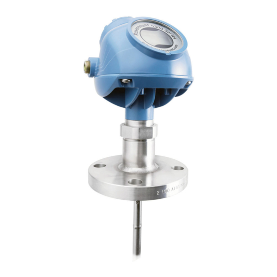
Transmitter overview Reference Manual April 2019 00809-0100-4530 Solids measurement Rosemount 5303, with a flexible single lead probe, is the solution for solids, powders and granules. It measures independently of dust, angled surfaces etc. High-pressure saturated steam applications The Rosemount 5300 Level Transmitter with Dynamic Vapor Compensation will automatically compensate for dielectric changes in high pressure steam applications and maintain the level accuracy. - Page 15 Reference Manual Transmitter overview 00809-0100-4530 April 2019 Figure 2-2: Transmitter Components ® ® A. Cable entry: ½-in. NPT; Optional adapters: M20, eurofast , minifast B. Radar electronics C. Flanged process connections D. Probe E. Dual compartment housing F. Threaded process connections G.
-
Page 16: System Integration
In this case, communication is restricted to digital, since current is fixed to the 4 mA minimum value. ™ The transmitter can be combined with the Emerson Wireless 775 THUM Adapter to ® wirelessly communicate HART data with IEC 62591 (WirelessHART ) technology. - Page 17 Reference Manual Transmitter overview 00809-0100-4530 April 2019 The transmitter can easily be configured using a handheld communicator or a PC with the Rosemount Radar Master software. Rosemount 5300 Level Transmitters can also be ™ configured with the AMS Suite and DeltaV software, and other tools supporting Electronic Device Description Language (EDDL) functionality.
- Page 18 Transmitter overview Reference Manual April 2019 00809-0100-4530 Figure 2-5: F Fieldbus System Architecture OUNDATION A. Handheld communicator B. Host/DCS system (e.g. DeltaV) C. Rosemount 5300 D. Rosemount 5400 E. Rosemount 5600 F. Maintenance G. Display H. H2 - High speed field bus I.
-
Page 19: Probe Selection Guide
Reference Manual Transmitter overview 00809-0100-4530 April 2019 Figure 2-6: HART to Modbus System Architecture A. Rosemount 5300 B. Power C. Handheld communicator D. Modbus, Levelmaster Emulation/RS-485 E. HART modem F. PC 5300 Setup in Rosemount Radar Master G. Control System H. - Page 20 Transmitter overview Reference Manual April 2019 00809-0100-4530 Table 2-1: Probe Selection Guide. G=Good, NR=Not Recommended, AD=Application Dependent (consult factory) (continued) Rigid single Flexible Coaxial Large Rigid twin Flexible lead, single lead coaxial lead twin lead segmented rigid single lead Pressure changes Temperature changes Condensing vapors Bubbling/boiling surfaces...
-
Page 21: Measuring Range
Reference Manual Transmitter overview 00809-0100-4530 April 2019 Table 2-1: Probe Selection Guide. G=Good, NR=Not Recommended, AD=Application Dependent (consult factory) (continued) Rigid single Flexible Coaxial Large Rigid twin Flexible lead, single lead coaxial lead twin lead segmented rigid single lead Liquid or vapor spray might touch probe above surface Disturbing... - Page 22 Transmitter overview Reference Manual April 2019 00809-0100-4530 Figure 2-7: Blind Zones and Areas with Reduced Accuracy A. Upper Reference Point B. Upper Blind Zone C. Reduced Accuracy D. Lower Blind Zone E. 20mA F. Range 0 -100 % G. 4mA H.
-
Page 23: Process Characteristics
Reference Manual Transmitter overview 00809-0100-4530 April 2019 Process characteristics The Rosemount 5300 Level Transmitter has high sensitivity because of its advanced signal processing and high signal to noise ratio. This makes it able to handle various disturbances, however, the following circumstances should be considered before mounting the transmitter. - Page 24 Transmitter overview Reference Manual April 2019 00809-0100-4530 2.7.6 Interface level measurement Rosemount 5302 is the ideal choice for measuring the level of oil, and the interface of oil and water, or other liquids with significant dielectric differences. Rosemount 5301 can also be used for interface measurement in applications where the probe is fully submerged in the liquid.
-
Page 25: Vessel Characteristics
Emulsion layers Sometimes there is an emulsion layer (mix of the products) between the two products which, depending on its characteristics, will affect interface measurements. For assistance with emulsion applications, consult your local Emerson representative. Vessel characteristics 2.8.1 Heating coils, agitators Because the radar signal is transmitted along a probe, the Rosemount 5300 Level Transmitter is generally not affected by objects in the tank. - Page 26 Transmitter overview Reference Manual April 2019 00809-0100-4530 Rosemount 5300 Level Transmitter...
-
Page 27: Chapter 3 Mechanical Installation
Reference Manual Mechanical installation 00809-0100-4530 April 2019 Mechanical installation Safety messages Instructions and procedures in this section may require special precautions to ensure the safety of the personnel performing the operations. Information that potentially raises safety issues is indicated by a warning symbol ( ). -
Page 28: Mounting Considerations
Emerson. Any continued use of product that has been damaged or modified without the written authorization is at the customer’s sole risk and expense. - Page 29 Reference Manual Mechanical installation 00809-0100-4530 April 2019 3.2.1 Recommended mounting position for liquids When finding an appropriate mounting position for the transmitter, the conditions of the tank must be carefully considered. The transmitter should be mounted so that the influence of disturbing objects is reduced to a minimum. For easy access to the transmitter make sure that it is mounted with sufficient service space.
- Page 30 Mechanical installation Reference Manual April 2019 00809-0100-4530 3.2.2 Recommended mounting for solids Figure 3-2: Recommended Mounting for Solids Consider the following guidelines when mounting the transmitter: • Do not mount near inlet pipes in order to avoid product filling on the probe. •...
- Page 31 Table 3-2 Table 3-3. A safety factor of 2 is included for the figures. Consult your local Emerson representative for more information. Table 3-2: Tensile Load for Unanchored 0.16 in. (4 mm) Flexible Single Lead Probe, lb...
- Page 32 Mechanical installation Reference Manual April 2019 00809-0100-4530 Table 3-3: Tensile Load for Unanchored 0.24 in. (6 mm) Flexible Single Lead Probe, lb (kN) Material Probe length 49 ft. (15 m) Probe length 115 ft. (35 m) Tank Ø= 10 ft. (3 Tank Ø= 39 ft.
- Page 33 Reference Manual Mechanical installation 00809-0100-4530 April 2019 Table 3-4: Recommended Minimum Free Space to Tank Wall or Other Objects in the Tank Probe type Condition Minimum clearance Rigid single lead/ Segmented rigid single lead Smooth metal tank wall 4 in. (100 mm) Disturbing objects such as pipes and beams 16 in.
- Page 34 The Trim Near Zone (TNZ) function may be necessary or an Hold Off Distance/Upper Null Zone (UNZ) setup may be required to mask the nozzle. Longer nozzles may be used in certain applications. Consult your local Emerson representative for details.
- Page 35 3 or 4 in. (75 or 100 mm) 2 in. (50 mm) The center rod must be placed more than 0.6 in. (15 mm) away from the pipe wall. Applicable to pipe schedule up to 40s,40. For higher pipe schedule consult your local Emerson representative. Note Metal pipes are preferred, especially in applications with low dielectric constant, to avoid disturbances from objects near the pipe.
- Page 36 Mechanical installation Reference Manual April 2019 00809-0100-4530 Figure 3-6: Mounting Single Probe in Chamber/Still Pipe A. Rigid single/segmented rigid single B. Flexible single Inlet pipe diameter N < Ø Effective measuring range L ≥12 in. (300 mm). Related information Dimensional drawings Rosemount 9901 Chamber Rosemount 9901 allows external mounting of process level instrumentation.
- Page 37 Reference Manual Mechanical installation 00809-0100-4530 April 2019 Figure 3-7: Side-and-Side and Side-and-Bottom Chambers A. Side-and-side dimension B. Side-and-bottom dimension C. Center-to-center When mounting in a Rosemount 9901 chamber, see Table 3-7 for information on probe length determination. Table 3-7: Probe Length Determination for Rosemount 9901 Chambers Chamber Probe length Side-and-side chamber...
- Page 38 Mechanical installation Reference Manual April 2019 00809-0100-4530 Probe type in chamber considerations When installing a Rosemount 5300 in a chamber, the single lead probe is recommended. Other probe types are more susceptible to build-up and are not recommended. exception is applications with liquefied gas > 40 bar, where a coaxial probe should be used. The probe must not touch the chamber wall, should extend the full height of the chamber, but not touch the bottom of the chamber.
- Page 39 Reference Manual Mechanical installation 00809-0100-4530 April 2019 proprietary chamber flanges, are available. See Proprietary flanges to identify the proprietary flanges. • Table 3-14 for guidelines on which disc size to use. • Table 3-8 for guidelines on the required probe length. Table 3-8: Required Probe Length in Chambers Chamber manufacturer Probe length...
- Page 40 Mechanical installation Reference Manual April 2019 00809-0100-4530 Figure 3-9: Insulated Chamber Insulated tanks for more information. 3.2.7 Installation in non-metallic tanks and open-air applications Avoid major sources of electrical disturbance in proximity of the installation, e.g. electrical motors, stirrers, servo mechanisms. Figure 3-10: Avoid Electromagnetic Disturbances For clean liquids, use a coaxial probe to reduce effect of potential electrical disturbances.
- Page 41 Reference Manual Mechanical installation 00809-0100-4530 April 2019 For optimal single lead probe performance in non-metallic tanks, the probe must be mounted with a metal flange, or screwed in to a metal sheet (d > 14 in./350 mm) if a threaded version is used. Figure 3-12: Mounting in Non-Metallic Tanks A.
- Page 42 Mechanical installation Reference Manual April 2019 00809-0100-4530 Table 3-9: Minimum Distance between Single Probes Product Minimum distance between probes Oil (DC = 2.1) 5.2 ft. (1.6 m) Water (DC = 80) 3.3 ft. (1.0 m) 3.2.10 Insulated tanks When the Rosemount 5300 is installed in high temperature applications, consider the maximum ambient temperature.
- Page 43 Reference Manual Mechanical installation 00809-0100-4530 April 2019 Figure 3-15: ESD System in a Separator A. High-high unit B. Low-low unit High-high unit The alarm levels must be located near the bottom inlet with considerable margin to the Blind Zones to ensure robust and accurate readings. See Set alarm limits for further information.
-
Page 44: Shorten The Probe
Mechanical installation Reference Manual April 2019 00809-0100-4530 Figure 3-17: Low-Low Unit A. UNZ = 14 in. (350 mm) B. Minimum 20 in. (500 mm) C. 20 mA D. 4 mA E. Warning F. Shutdown 3.2.12 Shipboard installations Transmitters with aluminum housing are not approved for open deck installations. For application conditions and limitations refer to the applicable shipboard approval. - Page 45 Reference Manual Mechanical installation 00809-0100-4530 April 2019 Figure 3-18: Shortening of Flexible Twin/Single Lead Probe A. Spacer B. Screws C. Minimum: 1.6 in. (40 mm) Procedure 1. Mark off the required probe length. Add at least 1.6 in. (40 mm) to the required probe length to be inserted into the weight.
- Page 46 Mechanical installation Reference Manual April 2019 00809-0100-4530 Note If the screws are not tightened according to the required torque, the weight may fall off. This is especially important for solid applications with high tensile loads on the probe. Postrequisites After shortening the probe make sure to update the transmitter configuration to the new probe length.
- Page 47 Reference Manual Mechanical installation 00809-0100-4530 April 2019 Postrequisites After shortening the probe make sure to update the transmitter configuration to the new probe length. Related information Probe length Reference Manual...
- Page 48 Mechanical installation Reference Manual April 2019 00809-0100-4530 3.3.3 Shorten the rigid twin lead probe Prerequisites The spacers are put closer together at the probe end. The maximum amount that can be cut is related to the ordered probe length (L). Figure 3-19: Maximum Shortening of Rigid Twin Lead Probe A.
- Page 49 Reference Manual Mechanical installation 00809-0100-4530 April 2019 Related information Probe length 3.3.4 Shorten the coaxial probe Prerequisites Note The HTHP coaxial probe must not be cut in field. Figure 3-20: Maximum Shortening of Coaxial Probe A. Ordered probe length (L) > 49 in. (1250 mm) B.
- Page 50 Mechanical installation Reference Manual April 2019 00809-0100-4530 2. Insert the centering piece. The centering piece is delivered from factory and should be used to prevent the spacers centering the rod from coming loose. 3. Cut the tube to the desired length. 4.
- Page 51 Reference Manual Mechanical installation 00809-0100-4530 April 2019 Large coaxial probe parts Figure 3-21: Components A. Set screw M4, 2 pcs B. Outer pipe C. Set screw M5 D. Inner probe (one to three pieces depending on probe length) E. Split pin F.
- Page 52 1960 ≤ X ≤ 2055 A new inner probe segement must be ordered, 2100 < L ≤ 4100 contact your local Emerson representative. 2055 < X < 4100 Cutting can be performed. Follow instruction, Shorten the large coaxial probe.
- Page 53 77.2 ≤ X ≤ 80.9 A new inner probe segement must be ordered, 82.7 < L ≤ 161.4 contact your local Emerson representative 80.9 < X < 161.4 Cutting can be performed. Follow instruction, Shorten the large coaxial probe.
- Page 54 Mechanical installation Reference Manual April 2019 00809-0100-4530 b) Unscrew the outer pipe counterclockwise. c) Slide the outer pipe down, approximately 20 cm. 2. Loosen the inner probe. a) Unscrew the set screw. b) Unscrew the inner probe counterclockwise. Rosemount 5300 Level Transmitter...
- Page 55 Reference Manual Mechanical installation 00809-0100-4530 April 2019 3. HP/C probes only: Collect the PTFE sleeve and locking pin for later use. 4. Pull the inner probe all the way through the outer pipe. 5. Mark where to cut the outer pipe. Reference Manual...
- Page 56 Mechanical installation Reference Manual April 2019 00809-0100-4530 6. Cut the outer pipe. 7. Gently remove the split pin at the end of the inner probe. Collect the split pin, centering disc and bushing. Keep all three parts safe for later use.
- Page 57 Reference Manual Mechanical installation 00809-0100-4530 April 2019 9. Cut the inner probe. 10. Drill a hole in the inner probe using the drilling fixture (included in your shipment). a) Place the drilling fixture aligned at the end of the inner probe. b) Drill all the way throught the fixture.
- Page 58 Mechanical installation Reference Manual April 2019 00809-0100-4530 13. Split and bend the legs around the inner probe. 14. Inspect the inner probe. Verify that all centering discs are in good shape and the probe segments are tightened. 15. Slide the inner probe through the outer pipe. 16.
- Page 59 Reference Manual Mechanical installation 00809-0100-4530 April 2019 17. HP/C probes only: Mount the PTFE sleeve while keeping the locking pin in a horizontal position. 18. Tighten the inner probe. 19. Tighten the set screw. Reference Manual...
-
Page 60: Centering Disc For Pipe Installations
Mechanical installation Reference Manual April 2019 00809-0100-4530 20. Tighten the outer pipe. 21. Tighten the two set screws. 22. Verify a gap of about 1 mm above the outer pipe. Postrequisites After shortening the probe make sure to update the transmitter configuration to the new probe length. - Page 61 Reference Manual Mechanical installation 00809-0100-4530 April 2019 Figure 3-23: Prevent the Probe from Contacting the Wall For the segmented rigid single lead probe, up to five PTFE centering discs can be mounted along the probe, but keep a minimum distance of two segments between the discs. Additionally, a disc in SST or PTFE (part number 03300-1655-xxxx) can be attached to the end of the probe.
- Page 62 Mechanical installation Reference Manual April 2019 00809-0100-4530 Table 3-14: Centering Disc Size Recommendation for Different Pipe Schedules Pipe size Pipe schedule 5s, 5 and 10s,10 40s, 40 and 80s, 80 2-in. 2-in. 2-in. 3-in. 3-in. 3-in. 2-in. 4-in. 4-in. 4-in. 4-in.
- Page 63 Reference Manual Mechanical installation 00809-0100-4530 April 2019 Figure 3-25: Clearance Distance between the Probe End and the Chamber Bottom A. A clearance distance of 1 in. (25 mm) between the probe end and the chamber bottom is recommended. 3.4.1 Mount a centering disc on flexible single/twin lead probe Prerequisites Note When using centering discs made of PTFE, note that the maximum temperature is 482 °F...
- Page 64 Mechanical installation Reference Manual April 2019 00809-0100-4530 13 mm 2. Secure the bolt by folding the tab washer. 3.4.2 Mount a centering disc on rigid single lead probe (8 mm) Note Centering discs shall not be used with PTFE covered probes. Procedure 1.
- Page 65 Reference Manual Mechanical installation 00809-0100-4530 April 2019 2. Mount the bushing, centering disc, and washer at the probe end. Note Do not mount the washer (A) if the centering disc material is PTFE, Alloy C-276, Duplex 2205, or Alloy 400. 3.
- Page 66 Mechanical installation Reference Manual April 2019 00809-0100-4530 3.4.3 Mount a centering disc on rigid single lead probe (13 Procedure 1. Drill two holes using the drilling fixture (included in your shipment). 2. Mount the bushings and centering disc at the probe end. 3.
-
Page 67: Mount Device On Tank
Reference Manual Mechanical installation 00809-0100-4530 April 2019 5. Secure the split pins. Mount device on tank Mount the transmitter with flange on a nozzle on top of the tank. The transmitter can also ® be mounted on a threaded or Tri-Clamp connection. - Page 68 Mechanical installation Reference Manual April 2019 00809-0100-4530 A. PTFE covered probe with protective plate 2. Lower the transmitter and probe with flange into the tank. 3. Tighten bolts and nuts with sufficient torque for the flange and gasket choice. 4. Loosen the nut that connects the transmitter head to the probe slightly. Rosemount 5300 Level Transmitter...
- Page 69 Reference Manual Mechanical installation 00809-0100-4530 April 2019 55 mm 5. Rotate the transmitter housing so the cable entries/display face the desired direction. 6. Tighten the nut. Torque 30 ft-lb (40 Nm) 55 mm Postrequisites Connect the wiring. Reference Manual...
- Page 70 Mechanical installation Reference Manual April 2019 00809-0100-4530 3.5.2 Tank connection with loose flange (plate design) The transmitter is delivered with head, flange and probe assembled into one unit. If, for some reason, these parts have been disassembled, mount the transmitter as described below.
- Page 71 Reference Manual Mechanical installation 00809-0100-4530 April 2019 5. Mount the transmitter head. Torque 30 ft-lb (40 Nm) 60 mm Postrequisites Connect the wiring. 3.5.3 Threaded tank connection Prerequisites Note PTFE covered probes must be handled carefully to prevent damage to the coating. Procedure 1.
- Page 72 Mechanical installation Reference Manual April 2019 00809-0100-4530 3. Lower the transmitter and probe into the tank. 4. Loosen the nut that connects the transmitter head to the probe slightly. 60 mm 5. Screw the adapter into the process connection. 52 mm / 60 mm Rosemount 5300 Level Transmitter...
- Page 73 Reference Manual Mechanical installation 00809-0100-4530 April 2019 6. Rotate the transmitter housing so the cable entries/display face the desired direction. 7. Tighten the nut. Torque 30 ft-lb (40 Nm) 60 mm Postrequisites Connect the wiring. 3.5.4 Bracket mounting Procedure 1. Mount the bracket to the pipe/wall. On pipe: A.
- Page 74 Mechanical installation Reference Manual April 2019 00809-0100-4530 On wall: 2. Mount the transmitter with probe to the bracket. ® 3.5.5 Tank connection with Tri-Clamp Prerequisites Note PTFE covered probes must be handled carefully to prevent damage to the coating. Procedure 1.
- Page 75 Reference Manual Mechanical installation 00809-0100-4530 April 2019 4. Loosen the nut that connects the transmitter head to the probe slightly. 60 mm 5. Rotate the transmitter housing so the cable entries/display face the desired direction. 6. Tighten the nut. Torque 30 ft-lb (40 Nm) 60 mm Reference Manual...
- Page 76 Mechanical installation Reference Manual April 2019 00809-0100-4530 Postrequisites Connect the wiring. 3.5.6 Segmented probe Segmented probe parts Figure 3-26: Segmented Probe Parts 15.2 (385) 31.5 (800) A. Safety ring B. Screw C. Top segment D. Split pin E. PTFE washer (optional) F.
- Page 77 Reference Manual Mechanical installation 00809-0100-4530 April 2019 Verifying probe length Segmented probe ordered with model code 4S Before installation, verify the probe length (L) on the label. If the probe length needs to be adjusted, see Adjust the probe length. Figure 3-27: Label A.
- Page 78 Mechanical installation Reference Manual April 2019 00809-0100-4530 2. Pre-assemble the safety ring. 3. Optional: If ordered, mount the centering disc on the bottom segment of the probe. Rosemount 5300 Level Transmitter...
- Page 79 Reference Manual Mechanical installation 00809-0100-4530 April 2019 4. Insert the support tool. 5. Optional: If ordered, mount the centering disc. • Maximum five pcs/probe • Minimum two segments between each centering disc Reference Manual...
- Page 80 Mechanical installation Reference Manual April 2019 00809-0100-4530 6. Mount a middle segment (hand tight). 7. Secure the split pin. Rosemount 5300 Level Transmitter...
- Page 81 Reference Manual Mechanical installation 00809-0100-4530 April 2019 8. Insert the second support tool. 9. Remove the first support tool and lower the probe into the tank. Reference Manual...
- Page 82 Mechanical installation Reference Manual April 2019 00809-0100-4530 10. Repeat Step 5-Step 9 until all segments are mounted. Make sure to finish with the top segment of the probe. 11. Seal and protect threads. Use anti-seize paste or PTFE tape according to your site procedures.
- Page 83 Reference Manual Mechanical installation 00809-0100-4530 April 2019 A. Flange/Tri-Clamp B. Threaded C. Gasket D. Sealant on threads (NPT) E. Gasket (BSPP (G)) 13. Tighten the stop screw and slide the safety ring into the groove. Reference Manual...
- Page 84 Mechanical installation Reference Manual April 2019 00809-0100-4530 14. Remove the support tool. 15. Mount the device on the tank. Rosemount 5300 Level Transmitter...
- Page 85 Reference Manual Mechanical installation 00809-0100-4530 April 2019 A. Flange B. Tri-Clamp C. Threaded 16. Rotate the housing to the desired direction. 17. Tighten the nut. Torque 30 ft-lb (40 Nm) 60 mm 18. Continue with the grounding step. Adjust the probe length Procedure 1.
- Page 86 Mechanical installation Reference Manual April 2019 00809-0100-4530 L, desired probe length: 2. Determine n, the number of middle segments needed for the desired probe length. Table 3-16. n, number of middle segments: 3. Calculate Y, the length of the bottom segment. See Table 3-16.
- Page 87 Reference Manual Mechanical installation 00809-0100-4530 April 2019 7. Optional: If a bottom centering disc is ordered, then drill two holes on the bottom segment using the drilling fixture. Table 3-16: Determination of Probe Segments for Standard Seal Desired probe length (L) Number of Length of bottom segment middle...
-
Page 88: Anchor The Probe
Mechanical installation Reference Manual April 2019 00809-0100-4530 Table 3-17: Determination of Probe Segments for HTHP/HP/C Seal Desired probe length (L) Number of Length of bottom segment middle segments (n) 17.3 ≤ L ≤ 48.8 440 ≤ L ≤ 1240 0 pc Y = L -17.3 Y = L - 440 48.8 <... - Page 89 Reference Manual Mechanical installation 00809-0100-4530 April 2019 The length of the loop will add to the Blind Zone. The location of the chuck will determine the beginning of the Blind Zone. The Probe Length should be configured as the distance from the Upper Reference Point to the top of the chuck.
- Page 90 Mechanical installation Reference Manual April 2019 00809-0100-4530 Figure 3-30: Flexible Twin/Single Lead Probe with Weight and Magnet A. Magnet Rigid single lead probe The rigid single lead probe can be guided by a tube welded on the tank bottom. Tubes are customer supplied.
- Page 91 Reference Manual Mechanical installation 00809-0100-4530 April 2019 Figure 3-32: Rigid Twin Lead Probe Secured to the Tank Wall A. Ø 0.3 in. (8 mm) Coaxial probe The coaxial probe can be secured to the tank wall by fixtures fastened to the tank wall. Fixtures are customer supplied.
- Page 92 Mechanical installation Reference Manual April 2019 00809-0100-4530 Figure 3-34: Coaxial Probe with Tube A. Drain Solids applications Pull the probe rope through a suitable anchoring point, e.g. a welded eye and fasten it with two clamps. It is recommended the probe is slack in order to prevent high tensile loads. The sag should be at least 1.5 in./10 ft.
-
Page 93: Chapter 4 Electrical Installation
Reference Manual Electrical installation 00809-0100-4530 April 2019 Electrical installation Safety messages Instructions and procedures in this section may require special precautions to ensure the safety of the personnel performing the operations. Information that potentially raises safety issues is indicated by a warning symbol ( ). -
Page 94: Cable/Conduit Entries
Electrical installation Reference Manual April 2019 00809-0100-4530 Cable/conduit entries ® The electronics housing has two entries for ½ - 14 NPT. Optional M20×1.5, minifast ® eurofast adapters are also available. The connections are made in accordance with local or plant electrical codes. Make sure that unused ports are properly sealed to prevent moisture or other contamination from entering the terminal block compartment of the electronics housing. -
Page 95: Cable Selection
Reference Manual Electrical installation 00809-0100-4530 April 2019 • trimmed close and insulated from touching the transmitter housing. • continuously connected throughout the segment. • connected to a good earth ground at the power supply end. Figure 4-2: Cable Shield A. Insulate shield B. -
Page 96: Hazardous Areas
Electrical installation Reference Manual April 2019 00809-0100-4530 Hazardous areas When the Rosemount 5300 Level Transmitter is installed in a hazardous area, local regulations and specifications in applicable certificates must be observed. ® 4-20 mA/HART communication 4.6.1 Power requirements Terminals in the transmitter housing provide connections for signal cables. The Rosemount 5300 Level Transmitter is loop-powered and operates with the following power supplies: Table 4-1: External Power Supply for HART... - Page 97 Reference Manual Electrical installation 00809-0100-4530 April 2019 Table 4-2: Minimum Input Voltage (U ) at Different Currents Hazardous approval Current 3.75 mA 21.75 mA Minimum input voltage (U Non-hazardous installations, intrinsically safe 16 Vdc 11 Vdc installations and Non-sparking installations Explosion-proof/flameproof installations 20 Vdc 15.5 Vdc...
- Page 98 Electrical installation Reference Manual April 2019 00809-0100-4530 Figure 4-6: Explosion-Proof /Flameproof (Ex d) Installations A. Loop Resistance (Ohms) B. External Power Supply Voltage (Vdc) C. Operating region Note For the Ex d case, the diagram is only valid if the load resistance is at the + side and if the - side is grounded, otherwise the maximum load resistance is limited to 435 Ω.
-
Page 99: Hart
Reference Manual Electrical installation 00809-0100-4530 April 2019 For flameproof/explosion-proof applications the resistance between the negative terminal on the transmitter and the power supply must not exceed 435 Ω. Note For flameproof/explosion-proof installations, make sure the transmitter is grounded to the internal ground terminal inside the terminal compartment in accordance with national and local electrical codes. - Page 100 Electrical installation Reference Manual April 2019 00809-0100-4530 Table 4-3: Connection Terminals (continued) Connector label Description Comment Modbus RS-485 B connection Connect to RTU (RX/TX+) Modbus RS-485 A connection (RX/TX-) POWER + Positive power input terminal Apply +8 Vdc to +30 Vdc (max. rating) POWER - Negative power input terminal...
- Page 101 Reference Manual Electrical installation 00809-0100-4530 April 2019 4.7.8 Wiring diagram ® Figure 4-9: Wiring Diagram for RS-485 with Modbus A. “A” line B. “B” line C. 120 Ω D. RS-485 Bus E. Power supply F. HART - G. HART + H.
- Page 102 Electrical installation Reference Manual April 2019 00809-0100-4530 Note The HART to Modbus Converter (HMC) equipped transmitter contains intrinsically safe circuits that require the housing to be grounded in accordance with national and local electrical codes. Failure to do so may impair the protection provided by the equipment. Figure 4-10: Multidrop Connection of 5300 Level Transmitters A.
- Page 103 Reference Manual Electrical installation 00809-0100-4530 April 2019 Figure 4-11: Alternative Multidrop Connection of 5300 Level Transmitters A. “A” line B. “B” line C. 120Ω D. RS-485 bus E. Modbus Master F. Power supply G. Internal ground screw H. External ground screw Star topology For a star topology connection of the Rosemount 5300 Level Transmitter, the transmitter with the longest cable run needs to be fitted with a 120-Ω...
- Page 104 Electrical installation Reference Manual April 2019 00809-0100-4530 Figure 4-12: Star Topology Connection of Rosemount 5300 Level Transmitters A. For star topology connection, connect the 120 Ω termination resistor to the transmitter with the longest cable run. ® 4.7.10 External HART devices (slaves) ®...
-
Page 105: Foundation ™ Fieldbus
Reference Manual Electrical installation 00809-0100-4530 April 2019 Figure 4-13: The HMC Module Supports up to Four External Devices (Slaves) A. RS-485 bus B. Power supply C. Up to four external devices D. External HART device 2 E. External HART device 1 ™... - Page 106 Electrical installation Reference Manual April 2019 00809-0100-4530 4.8.2 Connecting fieldbus devices Figure 4-14: Rosemount 5300 Level Transmitter Field Wiring A. Integrated power conditioner and filter B. Power supply ™ C. F Fieldbus configuration tool OUNDATION D. (The power supply, filter, first terminator, and configuration tool are typically located in the control room.) E.
-
Page 107: Connect Wiring And Power Up
Reference Manual Electrical installation 00809-0100-4530 April 2019 4.8.3 Wiring diagram Figure 4-15: Wiring Diagram for F Fieldbus OUNDATION A. Handheld communicator B. Approved IS barrier (for Intrinsically Safe installations only) C. F Fieldbus modem OUNDATION D. Power supply Note Rosemount 5300 Level Transmitters with flameproof/explosion-proof output have a built- in barrier;... - Page 108 Electrical installation Reference Manual April 2019 00809-0100-4530 3. Remove the plastic plugs. 4. Pull the cable through the cable gland/conduit. Adapters are required if M20 glands are used. 5. Connect the cable wires (see Figure 4-7, Figure 4-15, and Figure 4-9).
- Page 109 Reference Manual Electrical installation 00809-0100-4530 April 2019 8. Tighten the cable gland. Note Apply PTFE tape or other sealant to the threads. Note Make sure to arrange the wiring with a drip loop. Mount the cover making sure the cover is secure to meet explosion-proof requirements.
-
Page 110: Optional Devices
Electrical installation Reference Manual April 2019 00809-0100-4530 11. Connect the power supply. 4.10 Optional devices ™ ® ™ 4.10.1 Rosemount 333 HART Tri-Loop The Rosemount 5300 Level Transmitter outputs a HART signal with four process variables. By using the Rosemount 333 HART Tri-Loop, up to three additional analog 4-20 mA outputs are provided. - Page 111 Reference Manual Electrical installation 00809-0100-4530 April 2019 Refer to the Rosemount 333 HART Tri-Loop Reference Manual for further information on how to install and configure the Rosemount 333. 4.10.2 Rosemount 751 Field Signal Indicator Figure 4-17: Wiring Diagram for a Rosemount 5300 Transmitter with Rosemount 751 Field Signal Indicator A.
- Page 112 Electrical installation Reference Manual April 2019 00809-0100-4530 Rosemount 5300 Level Transmitter...
-
Page 113: Chapter 5 Configuration
Reference Manual Configuration 00809-0100-4530 April 2019 Configuration Safety messages Instructions and procedures in this section may require special precautions to ensure the safety of the personnel performing the operations. Information that potentially raises safety issues is indicated by a warning symbol ( ). - Page 114 Configuration Reference Manual April 2019 00809-0100-4530 5.2.1 Basic configuration The basic configuration includes parameters for a standard configuration which is sufficient in most cases. The basic configuration comprises the following items: • Measurement units • Tank configuration - Tank geometry - Environment - Volume •...
-
Page 115: Host System Integration
Verify that the latest Device Driver (DD/DTM ) is loaded on your systems to ensure proper communication. See Table 5-1. • Download the latest Device Driver from Emerson.com/DeviceInstallKits. Table 5-1: Rosemount 5300 Device Revisions and Files Firmware version Find Device Driver ® HART... - Page 116 Configuration Reference Manual April 2019 00809-0100-4530 5.3.2 Set alarm limits The alarm limits that are set in the host system need to be adjusted for the expected maximum product level rate and configured Damping Value. When setting the high alarm limit, a safety margin (see Figure 5-1) should be subtracted from the desired high alarm limit.
- Page 117 Reference Manual Configuration 00809-0100-4530 April 2019 Table 5-2: Safety Margin in Inches and Millimeters Level Rate in/min (mm/ Damping Value min) 2 s (default) 10 s 20 s 50 s Level Rate > 6.40 (160) 0.25 × Level Rate 0.60 × Level Rate 0.90 ×...
- Page 118 Configuration Reference Manual April 2019 00809-0100-4530 Desired high level alarm limit = 8500 mm High alarm limit = Desired high alarm limit - Safety margin = 8500 - 85 = 8415 mm Figure 5-2: Example - Determine High Alarm Limit A.
-
Page 119: Establish Hart ® Communication For Transmitter With Hart To Modbus ® Converter
Reference Manual Configuration 00809-0100-4530 April 2019 ® Establish HART communication for ® transmitter with HART to Modbus Converter The Rosemount 5300 Level Transmitter can be configured using the Rosemount Radar Master PC software or a handheld communicator. Configuration is done by sending HART commands through the HART to Modbus Converter (HMC) to the 5300 Level Transmitter electronics. - Page 120 Configuration Reference Manual April 2019 00809-0100-4530 f) Select OK. 4. Connect the power wires (or cycle power) to the transmitter. 5. Wait 20 seconds, and then search for and connect to device. a) Select Device → Search. b) Make sure HART address 1 is being scanned (also see Establish communication when multiple 5300/5400 Modbus units are on the bus).
- Page 121 Reference Manual Configuration 00809-0100-4530 April 2019 After a while the Search Device window presents a list of found transmitters. d) Select the device from the list and select OK to connect. 6. After completing the configuration, disconnect the RS-485 Converter, connect the Modbus communication wires and cycle power to the transmitter.
-
Page 122: Basic Configuration Using Rosemount Radar Master
Configuration Reference Manual April 2019 00809-0100-4530 Note Measurement data is not updated to the Modbus Master when a configuration tool is connected. Basic configuration using Rosemount Radar Master The Rosemount Radar Master (RRM) is a user-friendly software tool that allows the user to configure the Rosemount 5300 Level Transmitter. - Page 123 Reference Manual Configuration 00809-0100-4530 April 2019 ® 5.5.3 Installing the RRM software for HART communication To install the Rosemount Radar Master: Procedure 1. Insert the installation CD into your CD-ROM drive. 2. If the installation program is not automatically started, choose Run from the Windows Start bar.
- Page 124 Configuration Reference Manual April 2019 00809-0100-4530 A. RRM communicates with the transmitter B. No communication with the transmitter 5.5.4 Specify the COM port If communication is not established, open the Communication Preferences window and check that the correct COM Port is selected: Procedure 1.
- Page 125 Reference Manual Configuration 00809-0100-4530 April 2019 5.5.5 Set the COM port buffers For Windows 2000/XP/7 the COM port Receive Buffer and Transmit Buffer need to be set to 1. To set the COM port buffers: Procedure 1. In the MS Windows Control Panel, open the System option. 2.
- Page 126 Configuration Reference Manual April 2019 00809-0100-4530 If only Rosemount Radar Master is connected to the bus: • Device address = Fixed • Device Type = Link Master Device • Usage = NI-FBUS If other host systems are connected to the bus: •...
- Page 127 Reference Manual Configuration 00809-0100-4530 April 2019 8. Select the desired transmitter and select OK to connect. 9. In the RRM Status Bar, verify that RRM communicates with the transmitter. A. RRM communicates with the transmitter B. No communication with the transmitter 5.5.7 Specifying measurement units Measurement units for data presentation in RRM can be specified when the RRM program...
- Page 128 Configuration Reference Manual April 2019 00809-0100-4530 Figure 5-5: Device Config Window Table 5-4: Setup Functions in RRM Icon Description Wizard The Wizard is a tool that guides you through the basic configuration procedure of a Rosemount 5300 Level Transmitter. General Configuration of general settings such as communication parameters, device tag, and measurement units.
- Page 129 Reference Manual Configuration 00809-0100-4530 April 2019 5.5.9 Guided setup The following description shows how to use the Guided Setup in Rosemount Radar Master. The Guided Setup is useful if you are unfamiliar with the Rosemount 5300 Level Transmitter. Procedure 1. Start the Guided Setup. a) Start Rosemount Radar Master.
- Page 130 Configuration Reference Manual April 2019 00809-0100-4530 4. (Optional) In the Device Tag window, enter tag, message, descriptor, and date. The information is not required for the operation of the transmitter and can be left out if desired. 5. In the Digital Units window, select the digital units of measurement for the device. Rosemount 5300 Level Transmitter...
- Page 131 Reference Manual Configuration 00809-0100-4530 April 2019 6. In the Probe window, check configuration of Probe Type. The following Probe Types are available: • Rigid twin • Flexible twin • Coaxial, coaxial HP/C, coaxial HTHP • Coaxial Large, Coaxial Large HP/C •...
- Page 132 Configuration Reference Manual April 2019 00809-0100-4530 c) If using pipe, chamber or nozzle, then select the Pipe/Chamber/Nozzle Inner Diameter. d) If using nozzle, then enter the Nozzle Height. 9. In the Environment window, specify tank environment. a) Select the Measurement Mode. See Measurement mode for further information.
- Page 133 Reference Manual Configuration 00809-0100-4530 April 2019 11. If an ideal tank shape is selected, then enter the Diameter and Length (not for spherical tanks). See Standard tank shapes for further information. 12. If Strapping Table is selected, starting at the bottom of the tank, for each new point, enter the total volume up to the specified level value.
- Page 134 Configuration Reference Manual April 2019 00809-0100-4530 This is the last window in the Configuration Wizard concluding the basic configuration. The current configuration can be changed at any time using the setup windows (General, Tank, Output etc., see Using the setup functions).
- Page 135 Reference Manual Configuration 00809-0100-4530 April 2019 2. Choose the tank material if recommended. 3. Proceed to Restart the device if no configuration is needed. Trim Near Zone is described further in Trim near zone function. Probe End Projection is described further in Probe end projection.
- Page 136 Configuration Reference Manual April 2019 00809-0100-4530 If any difference, the Calibration Distance parameter will be adjusted. A minor adjustment using Calibration Distance is normal. There may, for example be a deviation between the actual tank height and the configured value. Figure 5-6: Calibration Distance A.
- Page 137 Reference Manual Configuration 00809-0100-4530 April 2019 2. Follow the on-screen instructions. Note The offset (Calibration Distance parameter) is automatically set after completing the Verify Level method. An offset greater than 4 in. (100 mm) indicates a problem with the level measurement. Re-check configuration parameters. If these are correct, then view an echo plot and evaluate thresholds.
- Page 138 Configuration Reference Manual April 2019 00809-0100-4530 The Archive Device function will create an information package for support purposes. The package includes a complete backup of the device, several logs, and echo curves. View live values from device View live values from device to verify that the transmitter works correctly. Procedure 1.
-
Page 139: Basic Configuration Using Ams Device Manager And Handheld Communicator
Reference Manual Configuration 00809-0100-4530 April 2019 Basic configuration using AMS Device Manager and handheld communicator Basic configuration parameters for information on the various configuration parameters. 5.6.1 Connect to device using AMS Device Manager Procedure 1. Start AMS Device Manager. 2. Select View → Device Connection View. 3. -
Page 140: Basic Configuration Using Deltav
Configuration Reference Manual April 2019 00809-0100-4530 5.6.2 Connect to device using a handheld communicator Procedure Turn on the handheld communicator and connect to the device. 5.6.3 Configure device ® HART Procedure 1. Select Configure → Guided Setup. 2. Select Level Measurement Setup and follow the instructions. 3. - Page 141 Reference Manual Configuration 00809-0100-4530 April 2019 The Fieldbus Device Properties window lets you enter device tag and description. This information is not required for the operation of the transmitter and can be left out if desired. 4. Check that the general information complies with the ordering information. General information such as device type (Rosemount 5300), manufacturer, device ID are presented.
- Page 142 Configuration Reference Manual April 2019 00809-0100-4530 7. Check configuration of Probe Type. The following Probe Types are available: • Rigid twin • Flexible twin • Coaxial, coaxial HP/C, coaxial HTHP • Coaxial large, Coaxial large HP/C • Rigid single, rigid single HTHP/HP/C, rigid single PTFE •...
- Page 143 Reference Manual Configuration 00809-0100-4530 April 2019 13. If using nozzle, then enter the Nozzle Height. 14. Select the Environment tab. 15. Select the Measurement Mode. See Measurement mode for further information. 16. Enter the Product Dielectric Range/Upper Product Dielectric. See Product dielectric range Upper product dielectric constant...
-
Page 144: Oundation Fieldbus Overview
Configuration Reference Manual April 2019 00809-0100-4530 • Horizontal cylinder • Vertical bullet • Horizontal bullet 20. If an ideal tank shape is selected, then enter the Tank Diameter and Tank Length (not for spherical tanks). See Standard tank shapes for further information. 21. - Page 145 Reference Manual Configuration 00809-0100-4530 April 2019 configured to be written periodically, the device can stop its normal operation after it reaches its limit or fail to accept new values. 5.8.1 Assigning device tag and node address A Rosemount 5300 Level Transmitter is shipped with a blank tag and a temporary address (unless specifically ordered with both) to allow a host to automatically assign an address and a tag.
- Page 146 Configuration Reference Manual April 2019 00809-0100-4530 Advanced configuration transducer block The advanced configuration transducer block contains functions such as amplitude threshold settings for filtering of disturbing echoes and noise, simulation of measurement values, and strapping table for volume measurements. Level transducer block The level transducer block contains transmitter information including diagnostics and the ability to configure, set to factory defaults and restarting the transmitter.
-
Page 147: Modbus ® Communication Protocol Configuration
Thermo Electron Autopilot Modbus RTU, Levelmaster Levelmaster protocol should be used when using the Emerson Digital Level Sensor (DLS) User Program or Application Module together with the device. Use Modbus RTU in other cases. Modbus ASCII is not commonly used, since it doubles the amount of bytes for the same message as the Modbus RTU. - Page 148 Configuration Reference Manual April 2019 00809-0100-4530 It is also possible to enter a user-defined Modbus message in the Modbus String area. See Rosemount 5300 with HART to Modbus Converter for more details regarding each Modbus protocol. 6. Select Modbus protocol and type the desired Modbus address. 7.
- Page 149 Reference Manual Configuration 00809-0100-4530 April 2019 Procedure 1. Select: Overview → Device Information → Identification. 2. Enter desired string into the Message area. Rosemount 5300 with HART to Modbus Converter for details regarding each Modbus protocol and what strings to use. ®...
- Page 150 Configuration Reference Manual April 2019 00809-0100-4530 These three letters are used for safety and will eliminate the risk of changing the configuration data by mistake. A indicates that the following number is the new address (address 44). Leading zeroes are not needed. B4800 B indicates that the following number is the new baud rate (1200, 2400, 4800, 9600, 19200).
- Page 151 Reference Manual Configuration 00809-0100-4530 April 2019 Table 5-9: Levelmaster Communication Parameters (continued) Parameter Value Parity None Stop Bits To configure the Rosemount 5300 Level Transmitter to communicate with the host in this example, the following text string is written to the Modbus message area: HMC M2 A2 B9600 D7 PN S1.
- Page 152 Configuration Reference Manual April 2019 00809-0100-4530 To reset the communication parameters to default Modbus ASCII settings, use the following Modbus message: HMC M1 Modbus ASCII parameter configuration You want to use address 246 for the Rosemount 5300 Level Transmitter and the host uses the following parameters: Table 5-11: Parameters Used by the Host (In Case of Modbus ASCII, Example) Parameter...
-
Page 153: Configure The Alarm Output For The Modbus ® Transmitter
Reference Manual Configuration 00809-0100-4530 April 2019 ® 5.10 Configure the alarm output for the Modbus transmitter The output from the Modbus transmitter in case of an error (such as a field device malfunction) can be configured. Prerequisites If the Modbus communication setup has been changed, but the transmitter has not yet started to use the new configuration, then you need to disconnect the HART modem and wait up to 60 seconds for the change to take effect. - Page 154 Configuration Reference Manual April 2019 00809-0100-4530 7. After changing the Alarm Output configuration, disconnect the HART modem and wait up to 60 seconds for the change to take effect. In case the MA/MB terminals are used for connection to the HMC, disconnect the RS-485 Converter, cycle power to the transmitter, and wait up to 60 seconds for the change to take effect.
- Page 155 Reference Manual Configuration 00809-0100-4530 April 2019 5.10.1 Verify alarm output To verify the alarm output, use Rosemount Radar Master to simulate a device failure: Procedure 1. Establish HART communication with the transmitter through Rosemount Radar Master. 2. Select Tools → Simulation Mode. 3.
-
Page 156: Hart ® Multi-Drop Configuration
Configuration Reference Manual April 2019 00809-0100-4530 ® 5.12 HART multi-drop configuration The Rosemount 5300 Series Transmitter can be run in multidrop mode. In the multidrop mode each transmitter has a unique HART address. Figure 5-9: Multidrop Connection 5.12.1 Change the poll address using Rosemount Radar Master To set the desired address for multidrop operation: Procedure 1. - Page 157 Reference Manual Configuration 00809-0100-4530 April 2019 5.12.2 Change the poll address using a handheld communicator To set the desired address for multidrop operation: Procedure 1. Select Configure → Manual Setup → Device Setup → HART → Comm Settings. 2. Set Poll addr to the desired address for multidrop operation. •...
- Page 158 Configuration Reference Manual April 2019 00809-0100-4530 Rosemount 5300 Level Transmitter...
-
Page 159: Chapter 6 Operation
Emerson. Any continued use of product that has been damaged or modified without the written authorization is at the customer’s sole risk and expense. -
Page 160: Using The Display Panel
Operation Reference Manual April 2019 00809-0100-4530 Using the display panel ™ The Rosemount 5300 Level Transmitter uses an optional display panel for presentation of measurement data. When the transmitter is switched on, the display panel presents information such as transmitter model, measurement frequency, software version, ®... -
Page 161: Specify Display Panel Variables
Reference Manual Operation 00809-0100-4530 April 2019 Table 6-1: LCD Parameters and Presentation on Display (continued) Parameter Presentation on display Description Analog output current ANOUT 4 -20 mA current Percent range %RANGE Level value in percent of total measurement range Interface level IFLVL Level of the lower product Interface distance... - Page 162 Operation Reference Manual April 2019 00809-0100-4530 2. Select the LCD tab. 3. Select the variables to be shown on the display panel. a) Select the Store button to save the LCD settings in the transmitter database. 4. Select the Units tab. 5.
- Page 163 Reference Manual Operation 00809-0100-4530 April 2019 6.3.2 Specify display panel variables using AMS Device Manager Specify variables and corresponding measurement units to be presented on the display panel (LCD) screen: Procedure ® 1. HART : Select Configure → Manual Setup → Device Setup. ™...
- Page 164 Operation Reference Manual April 2019 00809-0100-4530 e) Select Send, and follow the instructions. 2. Specify measurment units: a) HART: Select Configure → Manual Setup → Device Setup. Fieldbus: Select Configure → Manual Setup. OUNDATION b) HART: Select Units. Fieldbus: Select LCD Units. OUNDATION c) Specify desired measurement units.
-
Page 165: View Measurement Data
Reference Manual Operation 00809-0100-4530 April 2019 View measurement data Measurement values can be viewed using Rosemount Radar Master, AMS Device Manager, handheld communicator, or other communicator. 6.4.1 View measurement data in Rosemount Radar Master To view measurement data in Rosemount Radar Master: Procedure 1. - Page 166 Operation Reference Manual April 2019 00809-0100-4530 Figure 6-3: Presentation of Analog Output Value in Rosemount Radar Master 6.4.2 View measurement data in AMS Device Manager and handheld communicator Current measurement data of the primary variables are presented on the Overview screen.
- Page 167 Reference Manual Operation 00809-0100-4530 April 2019 Figure 6-4: Presentation of Measurement Data in DeltaV for the Rosemount 5300 A. Level values B. Interface level values Reference Manual...
- Page 168 Operation Reference Manual April 2019 00809-0100-4530 Rosemount 5300 Level Transmitter...
-
Page 169: Service And Troubleshooting
Reference Manual Service and troubleshooting 00809-0100-4530 April 2019 Service and troubleshooting Safety messages Instructions and procedures in this section may require special precautions to ensure the safety of the personnel performing the operations. Information that potentially raises safety issues is indicated by a warning symbol ( ). - Page 170 Emerson. Any continued use of product that has been damaged or modified without the written authorization is at the customer’s sole risk and expense.
-
Page 171: Diagnostic Messages
Table 7-1: Device status Message Description Action Running Boot Software The application software could not be Contact Emerson Service Department. started. Device Warning A device warning is active. See Warning Messages for details. Device Error A device error is active. - Page 172 Table 7-2: Error Messages Message Description Action RAM error An error in the gauge data memory Contact Emerson service department. (RAM) has been detected during the startup tests. Note This automatically resets the gauge. FPROM error An error in the gauge program memory Contact Emerson service department.
- Page 173 Reference Manual Service and troubleshooting 00809-0100-4530 April 2019 7.2.3 Warnings Table 7-3 shows a list of diagnostic messages that may be displayed on the Integral Display, on the handheld communicator, or in Rosemount Radar Master. Warnings are less serious than errors and in most cases do not result in Analog Output alarms. In Rosemount Radar Master, warnings are indicated in the Diagnostics window.
- Page 174 Check Warning messages. If MicroWave sampled tank signal. Module (MWM) Warning is active, this might indicate a transmitter error. Contact Emerson Service Department. DeltaF not at setpoint The DeltaF is not correctly regulated. Check Warning Messages. If MicroWave Module (MWM) Warning is active, this might indicate a transmitter error.
- Page 175 Reference Manual Service and troubleshooting 00809-0100-4530 April 2019 Table 7-4: Measurement Status (continued) Message Description Action Sim mode 0 active The simulation mode is active. The given Turn off the simulation mode. measurements are simulated. Advanced Simulation Mode The advanced simulation mode is active. To turn off the Advanced Simulation active mode, set Holding Register 3600=0 (see...
- Page 176 Service and troubleshooting Reference Manual April 2019 00809-0100-4530 Table 7-5: Interface Status (continued) Message Description Action Can't handle max possible With the current configuration, the Accept the limitation or change the tank interface thickness maximum measurement range is too environment and device configuration. short to guarantee that the interface echo can always be found.
-
Page 177: Lcd Error Messages
Reference Manual Service and troubleshooting 00809-0100-4530 April 2019 Note Analog output status messages may not appear on the integral display while the Rosemount 5300 Level Transmitter runs in HART 7 multidrop mode. Table 7-7: Analog Output Status Message Description Action Not connected Analog output hardware is not connected. -
Page 178: Led Error Messages
Service and troubleshooting Reference Manual April 2019 00809-0100-4530 Table 7-8: Error Messages Displayed on the Rosemount 5300 Display Panel (continued) Error message Description FPROM FAIL An error in the gauge program memory (FPROM) has been detected during the startup tests. Note This resets the gauge automatically. - Page 179 Reference Manual Service and troubleshooting 00809-0100-4530 April 2019 Figure 7-2: Rosemount 5300 Level Transmitter with LED A. Flashing LED In normal operation, the LED flashes once every other second. When an error occurs, the LED flashes a sequence that corresponds to the Code number followed by a five second pause.
-
Page 180: Foundation ™ Fieldbus Error Messages
Service and troubleshooting Reference Manual April 2019 00809-0100-4530 Figure 7-3: Flash Sequence Example A. Seconds ™ Fieldbus error messages OUNDATION 7.5.1 Resource block This section describes error conditions found in the Resource block. Read Table 7-10 through Table 7-12 to determine the appropriate corrective action. Block errors Table 7-10 lists conditions reported in the BLOCK_ERR parameter. - Page 181 Reference Manual Service and troubleshooting 00809-0100-4530 April 2019 Table 7-12: Resource Block DETAILED_STATUS with Recommended Action Messages Condition name RECOMMENDED action LOI Transducer block error • Restart processor • Check display connection • Call service center Sensor Transducer block error •...
- Page 182 Service and troubleshooting Reference Manual April 2019 00809-0100-4530 Table 7-15: AI BLOCK_ERR Conditions Condition Condition name Description number Other Block Configuration Error The selected channel carries a measurement that is incompatible with the engineering units selected in XD_SCALE, the L_TYPE parameter is not configured, or CHANNEL = zero.
-
Page 183: Troubleshooting Guide
Reference Manual Service and troubleshooting 00809-0100-4530 April 2019 Table 7-16: Troubleshooting the AI Block (continued) Symptom Possible causes Recommended actions Mode will not leave OOS Target mode not set Set target mode to something other than OOS. Configuration error BLOCK_ERR will show the configuration error bit set. - Page 184 Service and troubleshooting Reference Manual April 2019 00809-0100-4530 Table 7-17: Troubleshooting Chart Symptom Possible cause Action No level reading • Power disconnected • Check the power supply • Data communication cables • Check the cables for serial data disconnected communication •...
- Page 185 • Nozzle Height the tank. • Upper Product Dielectric Constant • Lower Product Dielectric Constant Integral display does not • Check the display configuration work. • Check loop power • Check Display connection • Contact Emerson Service Department Reference Manual...
- Page 186 • Call Service Center A malfunctioning display panel may only be replaced by service personnel at the Emerson service department. A display must not be replaced when the transmitter is in operation. If the Rosemount 5300 Level Transmitter has been exposed to temperatures outside the specified limits, the device may stop its normal operation.
- Page 187 Reference Manual Service and troubleshooting 00809-0100-4530 April 2019 ® ® 7.6.1 Troubleshooting the HART to Modbus Converter Table 7-18: Troubleshooting the HART to Modbus converter Symptom Recommended actions No communication on RS-485 bus (MA, MB) • Check that the cables are connected. •...
- Page 188 Service and troubleshooting Reference Manual April 2019 00809-0100-4530 Table 7-18: Troubleshooting the HART to Modbus converter (continued) Symptom Recommended actions No communication with Levelmaster • See "No communication on RS-485 bus". protocol • Make sure the “Modbus communication protocol configuration” is done properly, see Modbus communication protocol configuration.
-
Page 189: Diagnostics
Reference Manual Service and troubleshooting 00809-0100-4530 April 2019 Diagnostics The following information about the device can be retrieved: • Device status, see Device status. • Device errors, see Errors. • Device warnings, see Warnings. • Measurement status, see Measurement status. •... - Page 190 Service and troubleshooting Reference Manual April 2019 00809-0100-4530 2. To view active alerts select Service Tools → Alerts. 7.7.3 View device status using a handheld communicator To view the device status and active alerts usinga a handheld commnicator: Procedure 1. To view device status select Overview. 2.
- Page 191 Reference Manual Service and troubleshooting 00809-0100-4530 April 2019 7.7.4 View device status in DeltaV ™ To view the device status window in DeltaV Procedure 1. In the DeltaV Explorer, select the desired transmitter icon, and the TRANSDUCER1100 block icon. 2. Select Status. 3.
-
Page 192: Level And Distance Calibration
Service and troubleshooting Reference Manual April 2019 00809-0100-4530 Level and distance calibration Level and distance calibration may be necessary when using a nozzle or pipe or if there are disturbances in the near zone caused by a physical object. Non-metallic (e.g. plastic) vessels and installation geometry may introduce an offset for the zero reference point. - Page 193 Reference Manual Service and troubleshooting 00809-0100-4530 April 2019 Figure 7-6: Distance Calibration A. Upper Reference Point B. Distance 7.8.2 Calibrate level Procedure 1. Measure the actual product level. 2. Adjust the Tank Height so the product level measured by the transmitter corresponds to the actual product level.
-
Page 194: Service And Troubleshooting Tools
Service and troubleshooting Reference Manual April 2019 00809-0100-4530 Service and troubleshooting tools 7.9.1 Analyzing the measurement signal Rosemount Radar Master and other tools using enhanced EDDL has powerful functions for advanced troubleshooting. Using the Echo Curve plot function, an instant view of the tank signal is shown. - Page 195 Reference Manual Service and troubleshooting 00809-0100-4530 April 2019 Note No reference peak will be included in the echo curve of a large coaxial probe. An internal reference point is used for the large coaxial probe. Product surface peak This peak indicates the product level and is caused by a reflection from the product surface.
- Page 196 Service and troubleshooting Reference Manual April 2019 00809-0100-4530 Figure 7-9: The Echo Curve Function Is a Useful Tool for Signal Analysis A. Device Config B. Tools The Echo Curve Analyzer window appears with the View/Record Mode tab (or the Configuration Mode tab) selected. The configuration mode tab The Configuration Mode tab lets you adjust the different amplitude thresholds.
- Page 197 Reference Manual Service and troubleshooting 00809-0100-4530 April 2019 Figure 7-10: Echo Curve Analyzer Plot in Configuration Mode A. Measurement Output B. Set Threshold The current level Measurement Output from the device is presented with an arrow at the top of the plot. Normally, the measurement output points directly at the surface echo peak, but if, for instance, the tank is empty, and there is no surface echo peak detected, the Measurement Output is still presented indicating the distance to the tank bottom.
- Page 198 Service and troubleshooting Reference Manual April 2019 00809-0100-4530 The view/record mode tab The View/Record Mode tab presents a plot of the current tank conditions. Each radar echo is displayed as a peak in the signal plot. When clicking the Echo Curve icon under Device Config/Tools, the Echo Curve Analyzer window appears with the View/Record Mode tab selected: Figure 7-11: An Echo Curve Plot in View/Record Mode A.
- Page 199 Reference Manual Service and troubleshooting 00809-0100-4530 April 2019 Use the echo curve analyzer with a handheld communicator Using a handheld communicator that supports the Electronic Device Description Language (EDDL) with enhancements allows you to view the Echo Curve, create an Amplitude Threshold Curve (ATC) and specify amplitude thresholds such as the Surface Threshold, Interface Threshold, and Reference Threshold.
- Page 200 Service and troubleshooting Reference Manual April 2019 00809-0100-4530 needed. But if the transmitter still does not track for example the product surface, it may be necessary to manually adjust the thresholds. Figure 7-12: Threshold Principle A. The echo peak is below the threshold (dotted line) and is suppressed by the device. B.
- Page 201 Reference Manual Service and troubleshooting 00809-0100-4530 April 2019 Full tank threshold Note By default, the Full Tank Threshold Offset value is 0 (function is not used). Do not use this function unless you are qualified. The Full Tank threshold is related to the Reference Threshold, and can be used for detecting that the tank is full.
- Page 202 Service and troubleshooting Reference Manual April 2019 00809-0100-4530 A. Amplitude (mV) B. Distance C. Surface Threshold D. Surface echo E. About ⅓ of surface echo amplitude • Make sure to include a 500 mV margin between the Surface Threshold and the surface echo amplitude over the entire measuring range.
- Page 203 D. Surface echo E. Disturbance F. At least 500 mV margin ™ Contact your local Emerson representative if the transmitter is still having difficulties to track the product surface after applying the guidelines. Guidelines for setting the interface threshold •...
- Page 204 Service and troubleshooting Reference Manual April 2019 00809-0100-4530 Figure 7-13: Typical Surface Echo Amplitude for Coaxial/Large Coaxial Probes 18000 16000 DC 80 14000 12000 DC 20 10000 DC 10 8000 DC 5 6000 DC 3 4000 DC 2.0 2000 DC 1.5 3.3 (1) 6.6 (2) 9.8 (3)
- Page 205 Reference Manual Service and troubleshooting 00809-0100-4530 April 2019 Figure 7-14: Typical Surface Echo Amplitude for Single Lead Probes 8000 7000 DC 80 6000 5000 4000 3000 2000 1000 DC 1.5 16 (5) 33 (10) 49 (15) 66 (20) 82 (25) 98 (30) 115 (35) A.
- Page 206 Service and troubleshooting Reference Manual April 2019 00809-0100-4530 Figure 7-15: Typical Surface Echo Amplitude for Twin Flex Probe 10000 DC 80 9000 8000 7000 6000 5000 4000 3000 2000 DC 1.5 1000 16 (5) 33 (10) 49 (15) 66 (20) 82 (25) 98 (30) 115 (35)
- Page 207 Reference Manual Service and troubleshooting 00809-0100-4530 April 2019 Figure 7-16: Typical Surface Threshold Values 3000 2500 2000 1500 1000 A. Amplitude (mV) B. Dielectric constant of upper product Adjust thresholds using Rosemount Radar Master Normally, the amplitude thresholds are automatically set by the Rosemount 5300 Transmitter, and no manual settings are needed.
- Page 208 Service and troubleshooting Reference Manual April 2019 00809-0100-4530 Figure 7-17: Threshold Settings in RRM Automatic threshold settings are enabled by default. In the Advanced Configuration window the Interface, Reference, Probe End and Full Tank thresholds can also be set manually. Adjust thresholds using a handheld communicator To adjust the amplitude thresholds: Prerequisites...
- Page 209 Reference Manual Service and troubleshooting 00809-0100-4530 April 2019 Automatic surface threshold When this option is selected, the transmitter automatically sets the Surface threshold to a constant value based on the configured Dielectric Constant of the product. Note that by enabling the Automatic Surface threshold setting, the Amplitude Threshold Curve (ATC) is replaced by a constant threshold value.
- Page 210 Service and troubleshooting Reference Manual April 2019 00809-0100-4530 Figure 7-19: Surface Threshold Is Too Low A. Amplitude B. Distance C. Disturbing echo misinterpreted as product surface D. Actual product surface By adjusting the Surface Threshold the product surface is properly detected as illustrated Figure 7-20.
- Page 211 Reference Manual Service and troubleshooting 00809-0100-4530 April 2019 Figure 7-21 illustrates a situation where the Interface Threshold is too high. The signal amplitude peak at the interface between the upper and lower products is not detected in this case. Figure 7-21: Echo Curve Plot Indicating that the Interface Threshold for the Interface Peak Is Too High A.
- Page 212 Service and troubleshooting Reference Manual April 2019 00809-0100-4530 Figure 7-22: After Changing the Interface Threshold the Transmitter Detects the Interface A. Amplitude B. Distance C. Surface Threshold D. After Interface Threshold is adjusted the interface is correctly detected. If the Lower Product Dielectric Constant is known, the corresponding configuration parameter can be changed as an alternative to adjusting the amplitude thresholds.
- Page 213 Reference Manual Service and troubleshooting 00809-0100-4530 April 2019 7.9.5 Logging measurement data By using the Log Device Registers function in the Rosemount Radar Master software, you can log Input and Holding registers over time. It is possible to choose from different pre- defined sets of registers.
- Page 214 Service and troubleshooting Reference Manual April 2019 00809-0100-4530 c) Under Group Registers, select one of the parameters, and then select the right arrow button (>), or select the double arrow button (>>) to add the whole group. 8. Enter the update rate. An update rate of for example 10 seconds means that the plot will be updated every 10 seconds.
- Page 215 Reference Manual Service and troubleshooting 00809-0100-4530 April 2019 3. Type a name of the backup file, and then select Save. Now the transmitter configuration is stored. 7.9.7 Upload a backup configuration to device To upload a backup configuration using Rosemount Radar Master: Procedure Select Device →...
- Page 216 Service and troubleshooting Reference Manual April 2019 00809-0100-4530 7.9.9 Open the configuration report The configuration report shows what configuration changes have been done to the transmitter compared to the factory configuration. The report compares a specified backup file with the default transmitter configuration. Procedure 1.
- Page 217 Reference Manual Service and troubleshooting 00809-0100-4530 April 2019 Figure 7-25: The Reset to Factory Settings Window in Rosemount Radar Master Reset to factory settings using AMS Device Manager This function resets all or a specific part of the holding registers to factory settings. Prerequisites Note It is recommended that a backup of the configuration is done before the factory reset.
- Page 218 Service and troubleshooting Reference Manual April 2019 00809-0100-4530 7.9.11 Use the simulation mode Use the simulation mode with Rosemount Radar Master This function can be used to simulate measurements and alarms. Procedure 1. Select Tools → Simulation Mode. 2. In the Distance (simulated) box, type the desired value. 3.
- Page 219 Reference Manual Service and troubleshooting 00809-0100-4530 April 2019 Figure 7-26: The Simulation Mode Window in Rosemount Radar Master Use the simulation mode with AMS Device Manager This function can be used to simulate measurements and alarms. Procedure 1. HART: Select Service Tools → Simulate → Simulate. Fieldbus: Service Tools →...
- Page 220 Service and troubleshooting Reference Manual April 2019 00809-0100-4530 7.9.12 Enter service mode in Rosemount Radar Master Service functions for advanced users are available in Rosemount Radar Master. All options in the Service menu are enabled when entering the service mode. Procedure 1.
- Page 221 Reference Manual Service and troubleshooting 00809-0100-4530 April 2019 Procedure 1. In Rosemount Radar Master, enter the service mode. a) Select Service → Enter Service Mode. b) Type the password and select Submit. The default password is "admin". 2. Select Service → View Input Registers. 3.
- Page 222 Service and troubleshooting Reference Manual April 2019 00809-0100-4530 Option Description Display values in hexadecimal (Hex) format. 4. In the View Holding Registers window, do one of the following: • To search for registers by name, select the Names checkbox, and then in the list, select the desired register group.
- Page 223 Reference Manual Service and troubleshooting 00809-0100-4530 April 2019 7.9.16 Write protection Write protect a transmitter using Rosemount Radar Master The transmitter can be protected from unintentional configuration changes by a password protected function. The default password is 12345. It is recommended that this password is not changed to facilitate service and maintenance of the transmitter.
-
Page 224: Application Challenges
Service and troubleshooting Reference Manual April 2019 00809-0100-4530 7.10 Application challenges 7.10.1 Handling disturbances at top of tank In addition to using the ATC, the Rosemount 5300 Level Transmitter supports alternative methods to filter out disturbances at the top of the tank, such as the Trim Near Zone and the Hold Off Distance/Upper Null Zone functions, which can be used to handle disturbances from narrow nozzles or nozzles with rough edges. - Page 225 Reference Manual Service and troubleshooting 00809-0100-4530 April 2019 Figure 7-28: Echo Curve Before and After Trim Near Zone A. Reference Peak B. Trim Near Zone C. 0-3.3 ft (0-1 m) Perform trim near zone using Rosemount Radar Master The Trim Near Zone function is used to fine tune performance in the area close to the tank top (Near Zone).
- Page 226 Service and troubleshooting Reference Manual April 2019 00809-0100-4530 Procedure 1. Select Setup → Advanced. 2. Select the Near Zone tab. 3. Select Trim Near Zone and follow the on-screen instructions. 4. When near zone trimming is complete, restart the device. a) Select Tools →...
- Page 227 Reference Manual Service and troubleshooting 00809-0100-4530 April 2019 Reset trim near zone using Rosemount Radar Master To reset the Trim Near Zone function to factory setttings: Procedure 1. Select Setup → Advanced. 2. Select the Near Zone tab. 3. Select Trim Near Zone. 4.
- Page 228 Service and troubleshooting Reference Manual April 2019 00809-0100-4530 Figure 7-29: Hold Off Distance/UNZ A. Upper Reference Point B. Hold Off Distance/UNZ C. Disturbance D. Surface peak E. Surface Threshold Set the hold off distance/upper null zone using Rosemount Radar Master Prerequisites Note By adjusting the Hold Off Distance/UNZ, the measuring range is reduced.
- Page 229 Reference Manual Service and troubleshooting 00809-0100-4530 April 2019 Figure 7-30: Identifying the Hold Off Distance/UNZ in the Echo Curve Plot A. Amplitude, mV B. Distance, m C. Hold Off Distance/UNZ D. Disturbance E. Surface peak F. Surface Threshold 2. Set the Hold Off Distance/UNZ to the desired value. a) Select Setup →...
- Page 230 Service and troubleshooting Reference Manual April 2019 00809-0100-4530 Figure 7-31: Identifying the Hold Off Distance/UNZ in the Echo Curve Plot A. Amplitude, mV B. Distance, m C. Hold Off Distance/UNZ D. Disturbance E. Surface peak F. Surface Threshold 2. Set the Hold Off Distance/UNZ to the desired value. ®...
- Page 231 Reference Manual Service and troubleshooting 00809-0100-4530 April 2019 Figure 7-32: Disturbing Echoes Can Be Filtered out by Creating an Amplitude Threshold A. Amplitude, mV B. Distance, m C. Disturbing object D. Measurement signal E. Amplitude Threshold Curve Signal quality metrics Build up on the probe and different surface conditions are factors that can affect signal and noise levels.
- Page 232 Service and troubleshooting Reference Manual April 2019 00809-0100-4530 7.10.3 Double bounce handling A double bounce echo occurs when a radar signal bounces back and forth between the product surface and the tank roof before it is detected by the transmitter. Double bounces are most likely to appear in metal water tanks.
- Page 233 Reference Manual Service and troubleshooting 00809-0100-4530 April 2019 • The configured dielectic constants are included in the evaluation of the echo peak amplitude and should therefore also be set correctly. Related information Upper product dielectric constant 7.10.4 Interface Level with Submerged Probe The measurement mode Interface Level with Submerged Probe is used to handle interface measurements when the product level is not visible, for example in a full chamber pipe as illustrated in...
-
Page 234: Upgrade The Hart ® To Modbus ® Converter Firmware Using Rosemount Radar Master
Service and troubleshooting Reference Manual April 2019 00809-0100-4530 Procedure 1. Select Setup → Tank. 2. Select the Environment tab. 3. Under Measurement Mode, select the Interface Level with submerged probe checkbox. 4. Select Store. Note Adjust Interface Threshold if the interface level pulse is not detected. Note that in submerged mode the interface is picked up by the surface threshold. - Page 235 Reference Manual Service and troubleshooting 00809-0100-4530 April 2019 • Parity: According to configuration in HMC (default None) • Handshake: RTS/CTS • Response Timeout: 1000 ms • Retries: 3 f) Select OK. 3. Search for and connect to device. a) Select Device → Search to open the Search Device window. If the HMC is configured for Modbus ASCII or Levelmaster communication, cycle the power to the transmitter and then open the Search Device window.
- Page 236 Service and troubleshooting Reference Manual April 2019 00809-0100-4530 c) Select Yes. Note An error message might be displayed when performing the Reset to Factory Settings operation. The operation has been successful if the checksum error has been cleared. 10. Select Tools → Restart Device. 11.
-
Page 237: Replace The Transmitter Head
Reference Manual Service and troubleshooting 00809-0100-4530 April 2019 b) Cycle the power to the HMC to exit the Modbus RTU communication mode. 7.12 Replace the transmitter head Prerequisites Note If the transmitter head must be removed from the probe, make sure that the process seal is carefully protected from dust and water. -
Page 238: Changing A Probe
Service and troubleshooting Reference Manual April 2019 00809-0100-4530 5. If the transmitter head is not mounted directly, attach the protection plug to the process seal to protect the exposed parts from dust and water. If a protection plug is not available, then cover the process seal with a plastic bag. 6. - Page 239 Reference Manual Service and troubleshooting 00809-0100-4530 April 2019 Table 7-19: Compatibility between Firmware Version and Probe Type Firmware Probe type version Standard HP/HTHP HP/HTHP/C with HTHP with Large coaxial without R2 R2 marking both R3 and HP/C marking only VC marking Earlier than 1.A4 1.A4...
- Page 240 Service and troubleshooting Reference Manual April 2019 00809-0100-4530 3. Check the software revision number (firmware version). a) In Rosemount Radar Master, select Device → Properties. Figure 7-36: Software Revision Number Rosemount 5300 Level Transmitter...
- Page 241 Reference Manual Service and troubleshooting 00809-0100-4530 April 2019 7.13.3 Replace the probe Figure 7-37: Probe Replacement A. Flange version B. Transmitter head C. Nut D. Process seal E. Probe F. Threaded version Procedure 1. Loosen the nut. Remove the transmitter head from the old probe. Make sure to protect the transmitter head bottom from dust and water.
-
Page 242: Service Support
Run verify level 7.14 Service support To expedite the return process outside of the United States, contact the nearest Emerson representative. Within the United States, call the Emerson Instrument and Valve Response Center using the 1-800-654-RSMT (7768) toll-free number. This center, available 24 hours a day, will assist you with any needed information or materials. - Page 243 Reference Manual Service and troubleshooting 00809-0100-4530 April 2019 Emerson Instrument and Valve Response Center representatives will explain the additional information and procedures necessary to return goods exposed to hazardous substances. Reference Manual...
- Page 244 Service and troubleshooting Reference Manual April 2019 00809-0100-4530 Rosemount 5300 Level Transmitter...
-
Page 245: Safety Instrumented Systems (4-20 Ma Only)
Emerson. Any continued use of product that has been damaged or modified without the written authorization is at the customer’s sole risk and expense. -
Page 246: Terms And Definitions
Safety Instrumented Systems (4-20 mA only) Reference Manual April 2019 00809-0100-4530 Terms and definitions Table 8-1: Terms and Definitions Term Definition Dangerous Undetected Failure In Time per billion hours FMEDA Failure Modes, Effects and Diagnostic Analysis ® HART Highway Addressable Remote Transducer Hardware Fault Tolerance Average Probability of Failure on Demand Safe Failure Fraction... -
Page 247: Safety-Certified Identification
Reference Manual Safety Instrumented Systems (4-20 mA only) 00809-0100-4530 April 2019 Safety-certified identification All Rosemount 5300 Level Transmitter must be identified as safety-certified before installing into SIS systems. Table 8-2 lists the versions of the Rosemount 5300 Level Transmitter that have been considered for the hardware assessment, to which this section applies. -
Page 248: Installation In Sis Applications
Safety Instrumented Systems (4-20 mA only) Reference Manual April 2019 00809-0100-4530 Figure 8-1: Device Properties Window A. Serial No B. Software/Firmware C. Safety Device (QS option) Installation in SIS applications The device should be installed and configured as a level sensing device per manufacturer’s instructions. -
Page 249: Configuring In Sis Applications
Reference Manual Safety Instrumented Systems (4-20 mA only) 00809-0100-4530 April 2019 It is assumed that the personnel installing, configuring, and operating the system have the knowledge equal or greater than that of a qualified Instrument Technician familiar with safety-related systems, process control applications, and general instrument use. Note The Rosemount 5300 Level Transmitter is not safety-rated during maintenance work, configuration changes, multidrop, loop test, or other activity that affects the safety... - Page 250 Safety Instrumented Systems (4-20 mA only) Reference Manual April 2019 00809-0100-4530 Figure 8-2: Alarm Levels and Operation Values 3.75 mA 4 mA 20 mA 21.75 mA 3.9 mA 20.8 mA 3.6 mA 4 mA 20 mA 22.5 mA 3.8 mA 20.5 mA A.
-
Page 251: Perform Proof Test For Sis Applications
Reference Manual Safety Instrumented Systems (4-20 mA only) 00809-0100-4530 April 2019 Perform proof test for SIS applications 8.7.1 Overview The following proof tests are recommended. If an error is found in the safety function, the measuring system must be switched out of service and the process held in a safe state by means of other measures. - Page 252 Safety Instrumented Systems (4-20 mA only) Reference Manual April 2019 00809-0100-4530 Tools required • HART host/communicator • Current meter 8.7.2 Prepare for proof-testing Prepare for proof-testing using Rosemount Radar Master Note that prior to these tests, inspect the echo curve to ensure that no disturbing echoes affecting the measurement performance are present.
- Page 253 Reference Manual Safety Instrumented Systems (4-20 mA only) 00809-0100-4530 April 2019 e) Click Stop to end loop test. 4. Using Loop Test, enter current value (mA) representing low alarm current. Verify that analog output current is correct using the reference meter. This step tests for possible quiescent current related failures.
- Page 254 Safety Instrumented Systems (4-20 mA only) Reference Manual April 2019 00809-0100-4530 Figure 8-3: Range Values A. Upper Reference Point B. Upper Blind Zone C. Reduced Accuracy D. Maximum Measuring Range E. Lower Blind Zone F. 20mA G. Range 0 -100 % H.
- Page 255 Reference Manual Safety Instrumented Systems (4-20 mA only) 00809-0100-4530 April 2019 a) Select Configure → Manual Setup → Device Setup → Security. b) Click Write Protect and follow the instructions. 3. Using Loop Test, enter current value (mA) representing high alarm current. Verify that analog output current is correct using the reference meter.
- Page 256 Safety Instrumented Systems (4-20 mA only) Reference Manual April 2019 00809-0100-4530 8.7.4 Suggested comprehensive, fully remote proof-test Suggested comprehensive, fully remote proof-test with Rosemount Radar Master The suggested proof-test described below will detect 85% of possible DU failures in the Rosemount 5300 Level Transmitters.
- Page 257 Reference Manual Safety Instrumented Systems (4-20 mA only) 00809-0100-4530 April 2019 Suggested comprehensive, fully remote proof-test with AMS Device Manager and handheld communicator The suggested proof-test described below will detect 85% of possible DU failures in the Rosemount 5300 Level Transmitters. Procedure 1.
- Page 258 Safety Instrumented Systems (4-20 mA only) Reference Manual April 2019 00809-0100-4530 8.7.5 Suggested partial proof-test Suggested partial proof-test with Rosemount Radar Master The suggested proof-test described below will detect 55% of possible DU failures in the Rosemount 5300 Level Transmitters. Procedure 1.
- Page 259 Reference Manual Safety Instrumented Systems (4-20 mA only) 00809-0100-4530 April 2019 Suggested partial proof-test with AMS Device Manager and handheld communicator The suggested proof-test described below will detect 55% of possible DU failures in the Rosemount 5300 Level Transmitters. Procedure 1.
- Page 260 Safety Instrumented Systems (4-20 mA only) Reference Manual April 2019 00809-0100-4530 8.7.6 Suggested comprehensive proof-test using reference reflector (High Level Supervision) Suggested comprehensive proof-test using reference reflector (High Level Supervision) with Rosemount Radar Master The suggested proof-test described below will detect 94% of possible DU failures in the Rosemount 5300 Level Transmitters.
- Page 261 Reference Manual Safety Instrumented Systems (4-20 mA only) 00809-0100-4530 April 2019 b) Select the Level Supervision tab. c) Select Start/Stop Test Mode. d) Verify that the output from the device corresponds to the alarm limit in the host system. e) End test mode by clicking Start/Stop Test Mode. The device will automatically exit the test mode after 30 minutes (default).
- Page 262 Safety Instrumented Systems (4-20 mA only) Reference Manual April 2019 00809-0100-4530 c) Enter current value representing low alarm current. d) Verify that analog output current is correct. e) Click Abort to end loop test. 5. Enable write protection. a) Select Configure → Manual Setup → Device Setup → Security. b) Click Write Protect and follow the instructions.
- Page 263 Reference Manual Safety Instrumented Systems (4-20 mA only) 00809-0100-4530 April 2019 3. Using Loop Test, enter current value (mA) representing high alarm current. Verify that analog output current is correct using the reference meter. a) Select Setup → Output → Analog Out 1 and click Loop test. b) Enter current value representing high alarm current.
- Page 264 Safety Instrumented Systems (4-20 mA only) Reference Manual April 2019 00809-0100-4530 Suggested comprehensive, fully remote proof-test using reference reflector (High Level Supervision) with AMS Device Manager and handheld communicator The suggested proof-test described below will detect 86% of possible DU failures in the Rosemount 5300 Level Transmitters.
- Page 265 Reference Manual Safety Instrumented Systems (4-20 mA only) 00809-0100-4530 April 2019 d) End test mode by clicking Start/Stop Test Mode. The device will automatically exit the test mode after 30 minutes (default). 7. Remove the bypass and otherwise restore normal operation. For more information on the High Level Supervision, refer to Rosemount 5300 Level Transmitter High Level Supervision Manual...
- Page 266 Safety Instrumented Systems (4-20 mA only) Reference Manual April 2019 00809-0100-4530 Suggested proof-test using reference reflector (High Level Supervision) with AMS Device Manager and handheld communicator The suggested proof-test described below will detect 82% of possible DU failures in the Rosemount 5300 Level Transmitters.
-
Page 267: Inspection
Reference Manual Safety Instrumented Systems (4-20 mA only) 00809-0100-4530 April 2019 b) Select the Level Supervision tab. c) Select Start/Stop Test Mode. d) Verify that the output from the device corresponds to the alarm limit in the host system. e) End test mode by clicking Start/Stop Test Mode. The device will automatically exit the test mode after 30 minutes (default). -
Page 268: Specifications
If the device needs to be reset to factory settings, please contact your local Emerson representative to get the factory pre-configuration file to be uploaded to the device or use the backup file created upon receiving the transmitter. This will ensure the proper settings for your safety device are configured and your QS or QT certificate is still valid. - Page 269 Reference Manual Safety Instrumented Systems (4-20 mA only) 00809-0100-4530 April 2019 Spare parts Additional spare parts are available in Spare parts and accessories. Reference Manual...
- Page 270 Safety Instrumented Systems (4-20 mA only) Reference Manual April 2019 00809-0100-4530 Rosemount 5300 Level Transmitter...
-
Page 271: Appendix A Specifications And Reference Data
Reference Manual Specifications and reference data 00809-0100-4530 April 2019 Specifications and reference data Performance specifications A.1.1 General Reference conditions Single Standard probe, 77 °F (25 °C) in water (DC=80) and ambient pressure in a 4-in. pipe using Trim Near Zone function. Reference accuracy ±... - Page 272 Coaxial 500 cP Not recommended Consult your local Emerson representative in the case of agitation/turbulence and high viscous products. Be cautious in HTHP viscous or crystallizing media applications where temperature at instrument connection is significantly lower than process temperature with risk of coating in the upper part of probe that may reduce the measurement signal.
- Page 273 Reference Manual Specifications and reference data 00809-0100-4530 April 2019 below, the values are a guideline for clean liquids. For more information, ask your local Emerson representative. Note For Remote Housing, see Table A-4 for the maximum recommended measuring range for different Remote Housing lengths, installation types, Dielectric Constants, and probe types.
- Page 274 Specifications and reference data Reference Manual April 2019 00809-0100-4530 Table A-3: Minimum Dielectric Constant Probe type Minimum dielectric constant HTHP (1)(2) Rigid single lead/ (1)(2) segmented rigid single (1.25 if installed in a metallic (1.4 if installed in a metallic bypass or stilling well) lead bypass or stilling well) Flexible single lead...
- Page 275 Reference Manual Specifications and reference data 00809-0100-4530 April 2019 Table A-4: Remote Housing Measuring Range, ft. (m) (continued) Rigid Rigid Flexible Coaxial/ Rigid twin Flexible single 8 single single Large twin coaxial 13 mm/ segmented rigid single Tank installations 1.4 9 (2.75) 9 (2.75) 9 (2.75)
- Page 276 Specifications and reference data Reference Manual April 2019 00809-0100-4530 Figure A-1: Maximum Upper Product Thickness for the Flexible Single Lead Probe 115 (35) 98 (30) 82 (25) 66 (20) 49 (15) 33 (10) 16 (5) A. Maximum upper product thickness, ft. (m) B.
- Page 277 Reference Manual Specifications and reference data 00809-0100-4530 April 2019 The following conditions will impact the Blind Zones: • If the single lead probes or twin probes are installed in a nozzle, the nozzle height shall be added to the specified Upper Blind Zone. •...
- Page 278 Specifications and reference data Reference Manual April 2019 00809-0100-4530 Figure A-4: Accuracy Over Measuring Range for Single Lead Probes (Rigid/Segmented Rigid/Flexible) ± ± ± ± 0.12 in. 1.18 in. 0.12 in. 1.18 in. (3 mm) (30 mm) (3 mm) (30 mm) 3.5 in.
- Page 279 Reference Manual Specifications and reference data 00809-0100-4530 April 2019 Figure A-6: Accuracy Over Measuring Range for Coaxial Probe ± ± ± ± 0.12 in. 1.18 in. 0.12 in. 1.18 in. (3 mm) (30 mm) (3 mm) (30 mm) 2 in. (5 cm) 3.5 in.
-
Page 280: Functional Specifications
High Alarm current. After that measurement is re-established and the 4-20mA output settles at the actual level value. ™ If a different start-up behavior is preferred, contact your local Emerson representatives. Rosemount 5300 Level Transmitter... - Page 281 Reference Manual Specifications and reference data 00809-0100-4530 April 2019 Figure A-8: Start-Up Sequence A. Current, mA B. Time, s C. High Alarm current D. Actual level value E. Low Alarm current ® A.2.3 4-20 mA HART (output option code H) Output Two-wire, 4-20 mA.
- Page 282 00809-0100-4530 ™ Emerson Wireless 775 THUM Adapter The optional Emerson Wireless 775 THUM Adapter can be mounted directly on the transmitter or by using a remote mounting kit. ® IEC 62591 (WirelessHART ) enables access to multivariable data and diagnostics, and adds wireless to almost any measurement point.
- Page 283 Reference Manual Specifications and reference data 00809-0100-4530 April 2019 Table A-6: Minimum Input Voltage (U ) at Different Currents Hazardous approval Current 3.75 mA 21.75 mA Minimum input voltage (U Non-hazardous installations, intrinsically safe 16 Vdc 11 Vdc installations and Non-sparking installations Explosion-proof/flameproof installations 20 Vdc 15.5 Vdc...
- Page 284 Specifications and reference data Reference Manual April 2019 00809-0100-4530 Blocks and execution time Block Execution time 1 Resource 3 Transducer 6 Analog Input (AI) 10 ms 1 Proportional/Integrate/Derivate (PID) 15 ms 1 Signal Characterizer (SGCR) 10 ms 1 Integrator (INT) 10 ms 1 Arithmetic (ARTH) 10 ms...
- Page 285 Reference Manual Specifications and reference data 00809-0100-4530 April 2019 External power supply The input voltage U for Modbus is 8-30 Vdc (max. rating). Wiring diagram ® Figure A-10: Wiring Diagram for RS-485 with Modbus A. “A” line B. “B” line C.
- Page 286 Specifications and reference data Reference Manual April 2019 00809-0100-4530 A.2.6 Display and configuration Integral display (option code M1) The integral digital display can toggle between: level, distance, volume, internal temperature, interface distance, interface level, peak amplitudes, interface thickness, percentage of range, analog current out. Note The display cannot be used for configuration purposes.
- Page 287 Reference Manual Specifications and reference data 00809-0100-4530 April 2019 Output variables Table A-8: Output Variables Variable 5301 5302 5303 PV, SV, TV, QV ✓ ✓ ✓ ✓ Level Distance to Level (Ullage) ✓ ✓ ✓ ✓ ✓ ✓ ✓ ✓ Level Rate ✓...
- Page 288 Specifications and reference data Reference Manual April 2019 00809-0100-4530 Diagnostics Suite (option code D01 or DA1) Signal Quality Metrics Diagnostics package that monitors the relations between surface, noise and threshold. The function can be used to detect abnormal conditions in the process such as probe contamination or sudden loss of signal strength.
- Page 289 Reference Manual Specifications and reference data 00809-0100-4530 April 2019 data is compared to the current measurement to verify the integrity of the measurement electronics and upper part of the probe. During the test, the transmitter will output a level corresponding to the reflector position, which can be used to verify the integrity of the transmitter output.
- Page 290 Specifications and reference data Reference Manual April 2019 00809-0100-4530 Table A-9: Temperature Ranges for Standard Tank Seals with Different O-ring Material O-ring material Temperature °F (°C) in air Minimum Maximum ® Viton Fluoroelastomer 5 (-15) 302 (150) Ethylene Propylene (EPDM) -40 (-40) 266 (130) ®...
- Page 291 Reference Manual Specifications and reference data 00809-0100-4530 April 2019 Figure A-12: Process Temperature and Pressure - Max Rating 5000 (345) 580 (40) 2940 (203) 232 (16) 1000 (69) -14 (-1) -14 (-1) -40 * (-40) (150) (-60) (38) (93) (204) (316) (400) 5000 (345)
- Page 292 Specifications and reference data Reference Manual April 2019 00809-0100-4530 Figure A-13: Ambient Temperature vs. Process Temperature 185 (85) 131 (55) 100 (38) 50 (10) 392 (200) 752 (400) -40 (-40) 600 (316) 200 (93) 400 (204) -320 -17 (-27) (-196) (427) -40 (-40) A.
- Page 293 Reference Manual Specifications and reference data 00809-0100-4530 April 2019 Table A-10: Ambient Temperature Limits (continued) Description Operating limit Storage limit Option code BR5 with integral -67 °F to 158 °F (-55 °C to 70 -76 °F to 185 °F (-60 °C to 85 °C) display °C) Integral display may not be readable and device display updates will be slower at temperatures...
- Page 294 Specifications and reference data Reference Manual April 2019 00809-0100-4530 Duplex 2205 (EN 1.4462) according to EN 1092-1 material group 16E0: (14) • Standard: Max. 580 psig (40 Bar), -22 °F (-30 °C) up to max 302 °F (150 °C) (14) •...
- Page 295 Reference Manual Specifications and reference data 00809-0100-4530 April 2019 Figure A-15: Protective Plate A. Alloy probe and protective plate B. PTFE covered probe and protective plate C. Protective plate Flange rating according to SST backing flange ASME B16.5 Table 2-2.3, EN 1092-1 material group 13E0, and JIS B2220 material group 2.3.
- Page 296 Specifications and reference data Reference Manual April 2019 00809-0100-4530 Table A-13: Process Connection with Plate Design Standard Bolting material Gasket Flange material Hub material Standard/HP/ HP/HTHP/C HTHP/C ASME Stainless steel Soft (1a) with min. Spiral wound Stainless steel SB574 Gr. N10276 SA193 B8M Cl.2 thickness 1.6 mm gasket with...
- Page 297 Reference Manual Specifications and reference data 00809-0100-4530 April 2019 Rosemount 5302 with the large coaxial probe provides the ability to continuously keep track of both level and interface level in fully submerged applications. The product level and interface level mode must be selected. Figure A-16: Interface Level Measurement A.
- Page 298 Sometimes there is an emulsion layer (mix of the products) between the two products which can affect interface measurements. For guidelines on emulsion situations, consult your local Emerson representative. For additional information, see the Guided Wave Radar Interface Measurement Technical Note.
- Page 299 Reference Manual Specifications and reference data 00809-0100-4530 April 2019 Figure A-17: Minimum Distance X and Minimum Measuring Span A. Level: 100% B. Minimum measuring span: 12 in. (300 mm) C. Level: 0% • If a Rosemount 5300 Level Transmitter is ordered from Rosemount together with a Rosemount 9901 Chamber, these space requirements are met by using the option code G1or G2 for the chamber.
-
Page 300: Physical Specifications
Emerson is not in a position to evaluate or guarantee the compatibility of the process fluid or other process parameters with the product, options, configuration or materials of construction selected. - Page 301 Reference Manual Specifications and reference data 00809-0100-4530 April 2019 Factory sealed Weight • Aluminum transmitter head: 4.4 lb (2 kg) • SST transmitter head: 10.8 lb (4.9 kg) A.3.4 Remote housing mounting Kit that includes a flexible armored extension cable and a bracket for wall or pipe mounting.
- Page 302 Specifications and reference data Reference Manual April 2019 00809-0100-4530 A.3.8 Pressure Equipment Directive (PED) Complies with 2014/68/EU article 4.3 A.3.9 Probes Probe versions Coaxial, Large Coaxial, Rigid Twin and Rigid Single Lead, Segmented Rigid Single Lead, Flexible Twin and Flexible Single Lead. Probes can be ordered in different materials and options for extreme temperatures and pressure.
- Page 303 Reference Manual Specifications and reference data 00809-0100-4530 April 2019 However, there are some restrictions for the standard and HP/C coaxial probes: Probes over 4.1 ft. (1.25 m) can be cut up to 2 ft. (0.6 m). Shorter probes can be cut to the minimum length of 1.3 ft.
- Page 304 Specifications and reference data Reference Manual April 2019 00809-0100-4530 Sideway capacity • Rigid single lead/Segmented rigid single lead: 4.4 ft. lbf, 0.44 lb at 9.8 ft. (6 Nm, 0.2 kg at 3 m) • Rigid twin lead: 2.2 ft. lbf, 0.22 lb at 9.8 ft. (3 Nm, 0.1 kg at 3 m) •...
- Page 305 Reference Manual Specifications and reference data 00809-0100-4530 April 2019 Table A-20: HP Probe (Operating Temperature and Pressure code P) Material of construction code Material exposed to tank atmosphere 316L (EN 1.4404), 316 , Ceramic (Al2O3), Graphite, PFA, PTFE, and Alloy 625 2 and H Alloy C-276 (UNS N10276), Ceramic (Al2O3), Graphite, PFA, PTFE, and Alloy 625...
- Page 306 Specifications and reference data Reference Manual April 2019 00809-0100-4530 Table A-23: End Weight Item Weight Standard weight for flexible single lead probe 0.88 lb (0.40 kg) (0.16-in./4 mm) Short weight (W2) for flexible single lead probe 0.88 lb (0.40 kg) (0.16-in./4 mm) Heavy weight (W3) for flexible single lead probe 2.43 lb (1.10 kg)
-
Page 307: Dimensional Drawings
Reference Manual Specifications and reference data 00809-0100-4530 April 2019 Dimensional drawings Figure A-20: Rigid Single Lead Probe with Flange Connection 7.1 (180) 5.2 (133) 3.4 (87) 3.6 (92) 7.4 (188.5) 10.1 (257.5) 15.6 (397.5) 15.6 (397.5) A. ½ - 14 NPT; optional adapters: M20x1.5, eurofast and minifast B. -
Page 308: April
Specifications and reference data Reference Manual April 2019 00809-0100-4530 ® Figure A-21: Rigid Single Lead Probe with Tri-Clamp Connection 7.1 (180) 5.2 (133) 3.4 (87) 3.6 (92) 7.4 (188.5) 10.1 (257.5) 10.1 (257.5) A. ½ - 14 NPT; optional adapters: M20x1.5, eurofast and minifast B. - Page 309 Reference Manual Specifications and reference data 00809-0100-4530 April 2019 Figure A-22: Rigid Single Lead with Threaded Connection 7.1 (180) 5.2 (133) 3.4 (87) 3.6 (92) 7.4 (188.5) 10.1 (257.5) 2.4 (62) 7.1 (180) 3.4 (87) 3.6 (92) 10.1 (257.5) 15.6 (397.5) 1.1 (27) A.
- Page 310 Specifications and reference data Reference Manual April 2019 00809-0100-4530 Figure A-23: Segmented Rigid Single Lead Probe with Flange Connection 7.1 (180) 5.2 (133) 3.4 (87) 3.6 (92) 7.4 (188.5) 10.1 (257.5) 15.6 (397.5) 0. 6 (15) 15.2 (385) 2.2 (55) 15.2 (385) 31.5 (800) Ø...
- Page 311 Reference Manual Specifications and reference data 00809-0100-4530 April 2019 Figure A-24: Segmented Rigid Single Lead Probe with Threaded Connection 7.1 (180) 5.2 (133) 3.4 (87) 3.6 (92) 7.4 (188.5) 10.1 (257.5) 0. 6 (15) 2.4 (62) 15.2 (385) 31.5 (800) 15.
- Page 312 Specifications and reference data Reference Manual April 2019 00809-0100-4530 Figure A-25: Single Rigid Vapor Probe for 2-in. Chambers 7.1 (180) 5.2 (133) 3.4 (87) 3.6 (92) 16 (397) 9 (226) (109) 1.1 (27) Ø 0.5 (13) Ø 0. 3 (8) A.
- Page 313 Reference Manual Specifications and reference data 00809-0100-4530 April 2019 Figure A-26: Flexible Single Lead Probe with Flange Connection 7. 1 (180) 5. 2 (133) 3.4 (87) 3.6 (92) 7. 4 (188.5) 10.1 (257.5) 15.6 (397.5) 15.6 (397.5) 5.5 (140) 5. 5 (140) 2 (50) 1 (26) Ø...
- Page 314 Specifications and reference data Reference Manual April 2019 00809-0100-4530 Figure A-27: Flexible Single Lead Probe with Tri-Clamp Connection 7.1 (180) 5.2 (133) 3.4 (87) 3.6 (92) 2 (50) 7.4 (188.5) Ø 1.5 (37.5) 10.1 (257.5) 5. 5 (140) Ø 1.5 (37.5) 1 (26) 5.5 (140) Ø...
- Page 315 Reference Manual Specifications and reference data 00809-0100-4530 April 2019 Figure A-28: Flexible Single Lead with Threaded Connection 7. 1 (180) 5. 2 (133) 7. 1 (180) 3.4 (87) 3.6 (92) 3.4 (87) 3.6 (92) 7. 4 (188.5) 10.1 (257.5) 10.1 (257.5) 2.4 (62) 1.1 (27) 5.
- Page 316 Specifications and reference data Reference Manual April 2019 00809-0100-4530 Figure A-29: Coaxial probe with Flange Connection 7.1 (180) 5.2 (133) 3.4 (87) 3.6 (92) 7.4 (188.5) 10.1 (257.1) Ø 1.1 (28) 15.6 (397.5) 15.6 (397. 5) Ø 1.5 (38) Ø 1.5 (38) A.
- Page 317 Reference Manual Specifications and reference data 00809-0100-4530 April 2019 Figure A-30: Coaxial Probe with Threaded Connection 7.1 (180) 5.2 (133) 7.1 (180) 3.4 (87) 3.6 (92) 3. 4 (87) 3. 6 (92) 10.1 10.1 (188.5) (257.1) (257.1) 15. 6 (397.5) 2.4 (62) 1.1 (27) Ø...
- Page 318 Specifications and reference data Reference Manual April 2019 00809-0100-4530 Figure A-31: Large Coaxial Probe with Flange Connection 7.1 (180) 5.2 (133) 3.4 (87) 3.6 (92) 7.4 (188.5) 10.1 (257.1) 2.4 (60) 2.4 (60) Ø 1.7 (42) 15.6 (397.5) A. ½ - 14 NPT; optional adapters: M20x1.5, eurofast and minifast B.
- Page 319 Reference Manual Specifications and reference data 00809-0100-4530 April 2019 Figure A-32: Large Coaxial Probe with Threaded Connection 7.1 (180) 5.2 (133) 7.1 (180) 3.4 (87) 3.6 (92) 3.4 (87) 3.6 (92) 10.1 (188.5) (257.1) 10.1 10.1 (257.1) (257.1) 1.1 (27) 2.4 (60) 2.4 (60) Ø...
- Page 320 Specifications and reference data Reference Manual April 2019 00809-0100-4530 Figure A-33: Integrated Still Pipe Vapor Probe for 3-in. Chambers and above 7.1 (180) 5.2 (133) 3. 4 (87) 3.6 (92) 7.4 (188.5) 16 (397) Ø 1.1 (28) Ø 1. 6 (42) Min.
- Page 321 Reference Manual Specifications and reference data 00809-0100-4530 April 2019 Figure A-34: Rigid Twin Lead Probe 7.1 (180) 7.1 (180) 5.2 (133) 3.4 (87) 3.6 (92) 3.4 (87) 3.6 (92) 7.4 (188. 5) 10. 2 (259.5) 10. 2 (259.5) 1.8 (45) 1.
- Page 322 Specifications and reference data Reference Manual April 2019 00809-0100-4530 Figure A-35: Flexible Twin Lead Probe 7.1 (180) 7.1 (180) 5.2 (133) 3.4 (87) 3.6 (92) 3.4 (87) 3.6 (92) 7.4 (188. 5) 10. 2 (259.5) 10. 2 (259.5) 1.8 (45) 1.
- Page 323 Reference Manual Specifications and reference data 00809-0100-4530 April 2019 Figure A-36: Mounting Bracket (Option Code BR) 5. 2 (133) 0.87 (22) 0.35 (9) 2.76 (70) 2.24 (57) A. Pipe mounting (vertical pipe) B. Pipe mounting (horizontal pipe) C. Wall mounting D.
-
Page 324: Proprietary Flanges
Specifications and reference data Reference Manual April 2019 00809-0100-4530 Figure A-37: Remote Housing (Option Code B1, B2, B3) 5.2 (133) 7 (180) (87) (92) 7.4 (188.5) 2.2 (57) 5.2 (133) 0.3 (7) (70) 0.8 (20) A. 3, 6, 9 ft. (1, 2, or 3 m) B. -
Page 325: Flushing Connection Rings
Reference Manual Specifications and reference data 00809-0100-4530 April 2019 : Flange thickness without gasket surface : Gasket surface thickness G: Gasket surface diameter # Bolts: Number of bolts K: Bolt hole circle diameter Dimensions are in inches (millimeters). Note Dimensions may be used to aid in the identification of installed flanges. It is not intended for manufacturing use. -
Page 326: Ordering Information
Specifications and reference data Reference Manual April 2019 00809-0100-4530 Table A-25: Pressure and Temperature Rating for Flushing Ring up to Class 2500 (continued) Flushing connection rings DN50 2.40 (61.0) 4.00 (102.0) ¼ in. NPT DN80 3.60 (91.4) 5.43 (138.0) ¼ in. NPT Ordering Information A.7.1 Rosemount 5301 and 5302 Level and/or Interface in... - Page 327 Reference Manual Specifications and reference data 00809-0100-4530 April 2019 Table A-26: Rosemount 5301 and 5302 Level and/or Interface in Liquids Ordering Information (continued) Operating temperature and pressure (see Process temperature and pressure Probe type rating) ★ Standard: 1A, 2A, 3A, 3B, 3C, 4A, 4B, 4S, 5A, and 5B - 15 to 580 psig @ 302 °F (-1 to 40 bar @ 150 °C)
- Page 328 Specifications and reference data Reference Manual April 2019 00809-0100-4530 Table A-26: Rosemount 5301 and 5302 Level and/or Interface in Liquids Ordering Information (continued) Probe type Process connections Probe lengths ★ Coaxial, perforated. For level and Flange / 1-in. , 1½-in., 2- in. Min: 1 ft.
- Page 329 Reference Manual Specifications and reference data 00809-0100-4530 April 2019 Table A-26: Rosemount 5301 and 5302 Level and/or Interface in Liquids Ordering Information (continued) (15) Total probe length (feet/m) ★ 0-164 ft. or 0-50 m (15) Total probe length (in./cm) ★ 0-11 in.
- Page 330 Specifications and reference data Reference Manual April 2019 00809-0100-4530 Table A-26: Rosemount 5301 and 5302 Level and/or Interface in Liquids Ordering Information (continued) 6-in. Class 150, RF (Raised Face Type) 1, 2, 3, 7, 8, H S, H, P, C EN 1092-1 flanges Material of construction Operating temperature...
- Page 331 Reference Manual Specifications and reference data 00809-0100-4530 April 2019 Table A-26: Rosemount 5301 and 5302 Level and/or Interface in Liquids Ordering Information (continued) ★ 50A, 10K, RF (Raised Face Type) 1, 2, 3, 7, 8 S, H, P, C ★ 80A, 10K, RF (Raised Face Type) 1, 2, 3, 7, 8 S, H, P, C...
- Page 332 Specifications and reference data Reference Manual April 2019 00809-0100-4530 Table A-26: Rosemount 5301 and 5302 Level and/or Interface in Liquids Ordering Information (continued) ★ Fisher - proprietary 316/316L (for 249B, 1, 7, 8 S, H, P, C 259B chambers) Torque Tube Flange ★...
- Page 333 Hydrostatic testing (19) ★ Hydrostatic testing Factory configuration ★ Factory configuration (Configuration Data Sheet required with order, available at Emerson.com/ Rosemount) Alarm limit configuration ★ Namur alarm and saturation levels, high alarm ★ Namur alarm and saturation levels, low alarm (20) ★...
- Page 334 Specifications and reference data Reference Manual April 2019 00809-0100-4530 Table A-26: Rosemount 5301 and 5302 Level and/or Interface in Liquids Ordering Information (continued) Country certification ★ Canadian Registration Number (CRN) (23) ★ ASME B31.1 (24) Indian Boiler Regulation (For witnessed Form III-C from factory, order certificate Q47 on separate line Item) (25)(26) ★...
- Page 335 Reference Manual Specifications and reference data 00809-0100-4530 April 2019 Table A-26: Rosemount 5301 and 5302 Level and/or Interface in Liquids Ordering Information (continued) Cold temperature (31)(32)(3 -67 °F (-55 °C) cold temperature 3)(34)(35) Verification reflectors (high level supervision) (36) Verification reflector for 3- to 6-in. pipe/chamber (High Level Supervision). See Verification reflector (option code HL1, HL2, or HL3) for details.
- Page 336 Specifications and reference data Reference Manual April 2019 00809-0100-4530 Table A-26: Rosemount 5301 and 5302 Level and/or Interface in Liquids Ordering Information (continued) Consolidate to chamber (see Rosemount 9901 Chamber) (41) Consolidate to Chamber Engineered solutions (see Engineered solutions) Rxxxx Engineered Solutions beyond standard model codes.
- Page 337 Reference Manual Specifications and reference data 00809-0100-4530 April 2019 (35) For ambient temperatures between -67 °F (-55 °C) and -40 °F (-40 °C), the ambient temperature effect is ± 0.012 in. (0.3 mm) /°K or ± 45 ppm/°K of measured value, whichever is greatest. Other performance specifications apply to ambient temperatures between –40 °F (–40 °C) and 185 °F (85 °C).
- Page 338 Specifications and reference data Reference Manual April 2019 00809-0100-4530 Table A-27: Rosemount 5303 Level for Solids Ordering Information (continued) Material of construction : process connection / probe Probe type ★ 316/316L/ EN 1.4404 Sealing, O-ring material (consult factory for other O-ring materials) ★...
- Page 339 Reference Manual Specifications and reference data 00809-0100-4530 April 2019 Table A-27: Rosemount 5303 Level for Solids Ordering Information (continued) ★ DN100, PN16, Type A flat face ★ DN100, PN40, Type A flat face DN50, PN40, Type E spigot face DN50, PN16, Type C tongue face DN50, PN40, Type C tongue face DN80, PN16, Type E spigot face DN80, PN40, Type E spigot face...
- Page 340 Specifications and reference data Reference Manual April 2019 00809-0100-4530 Table A-27: Rosemount 5303 Level for Solids Ordering Information (continued) ★ China Flameproof ★ USA Explosion-proof ★ Canadian Explosion-proof ★ IECEx Flameproof ★ ATEX Intrinsic Safety (10) ★ ATEX FISCO Intrinsic Safety ★...
- Page 341 Hydrostatic testing (12) ★ Hydrostatic testing Factory configuration ★ Factory configuration (Configuration Data Sheet required with order, available at Emerson.com/ Rosemount) Alarm limit configuration ★ Namur alarm and saturation levels, high alarm ★ Namur alarm and saturation levels, low alarm ★...
- Page 342 Specifications and reference data Reference Manual April 2019 00809-0100-4530 Table A-27: Rosemount 5303 Level for Solids Ordering Information (continued) Transient protection ★ Transient Protection Terminal Block. Selectable with HART 4-20 mA output (output code H). Already included in all F Fieldbus variations.
-
Page 343: Spare Parts And Accessories
Reference Manual Specifications and reference data 00809-0100-4530 April 2019 Spare parts and accessories Table A-28: Rosemount 5300 Series Spare Parts List - Transmitter Head Model Product description 5301 Guided Wave Radar Liquid Level or Interface Transmitter (interface available for fully submerged probe) 5302 Guided Wave Radar Liquid Level and Interface Transmitter... - Page 344 Specifications and reference data Reference Manual April 2019 00809-0100-4530 Table A-28: Rosemount 5300 Series Spare Parts List - Transmitter Head (continued) Total probe length (in./cm) Not Applicable Process Connection - size / type Not Applicable Hazardous locations certifications No Hazardous Locations Certifications ATEX Flameproof INMETRO Flameproof China Flameproof...
- Page 345 4–20 mA with digital signal based on HART 7 protocol Factory configuration Factory configuration (Configuration Data Sheet required with order, available at Emerson.com/Rosemount) Alarm limit configuration Namur alarm and saturation levels, high alarm Namur alarm and saturation levels, low alarm...
- Page 346 Specifications and reference data Reference Manual April 2019 00809-0100-4530 Table A-28: Rosemount 5300 Series Spare Parts List - Transmitter Head (continued) Overfill prevention (11) WHG Overfill Approval Extended product warranty (12) 3-year limited warranty (12) 5-year limited warranty Remote housing mounting 1 m/3.2 ft.
- Page 347 Reference Manual Specifications and reference data 00809-0100-4530 April 2019 Table A-29: Rosemount 5300 Series Spare Parts List - Probe (continued) High Temperature / High Pressure: 3A, 3B, 3V, 4A, 4B, 4S, 4U, 5A, and 5B 5000 psi @ 100 °F and 2940 psi @ 752 °F (345 bar @ 38 °C and 203 bar @ 400 °C) High Pressure: 3A, 3B, 3C, 4A, 4B, 4S, 5A,...
- Page 348 Specifications and reference data Reference Manual April 2019 00809-0100-4530 Table A-29: Rosemount 5300 Series Spare Parts List - Probe (continued) Flexible Twin Lead with Flange / 1½-in., 2-in. Min: 3 ft. 4 in. (1 m) Max: weight Thread 164 ft. (50 m) Coaxial (for level Flange / 1-in.
- Page 349 Reference Manual Specifications and reference data 00809-0100-4530 April 2019 Table A-29: Rosemount 5300 Series Spare Parts List - Probe (continued) (14) Total probe length (in./cm) 0-11 in. or 0-99 cm Process connection - size / type (consult factory for other process connections) ASME flanges Material of construction Operating temperature and...
- Page 350 Specifications and reference data Reference Manual April 2019 00809-0100-4530 Table A-29: Rosemount 5300 Series Spare Parts List - Probe (continued) 4-in. Class 150, RF (Raised 1, 2, 3, 7, 8, H, D S, H, P, C Face Type) 4-in. Class 300, RF (Raised 1, 2, 3, 7, 8, H, D S, H, P, C Face Type)
- Page 351 Reference Manual Specifications and reference data 00809-0100-4530 April 2019 Table A-29: Rosemount 5300 Series Spare Parts List - Probe (continued) DN80, PN63, Type A flat 1, 2, 3 H, P, C face DN80, PN100, Type A flat H, P, C face DN80, PN160, Type B2 H, P, C...
- Page 352 Specifications and reference data Reference Manual April 2019 00809-0100-4530 Table A-29: Rosemount 5300 Series Spare Parts List - Probe (continued) 50A, 20K, RF (Raised Face 1, 2, 3, 7, 8 S, H, P, C Type) 80A, 10K, RF (Raised Face 1, 2, 3, 7, 8 S, H, P, C Type)
- Page 353 Reference Manual Specifications and reference data 00809-0100-4530 April 2019 Table A-29: Rosemount 5300 Series Spare Parts List - Probe (continued) Fisher - proprietary 1, 7, 8 S, H, P, C 316/316L (for 249B, 259B chambers) Torque Tube Flange Fisher - proprietary 1, 7, 8 S, H, P, C 316/316L (for 249C...
- Page 354 Specifications and reference data Reference Manual April 2019 00809-0100-4530 Table A-29: Rosemount 5300 Series Spare Parts List - Probe (continued) Installation options (23) Long stud 9.8 in (250 mm) for flexible single lead probe to prevent contact with wall/ nozzle. Standard stud length is 3.9 in (100 mm) for probes 5A and 5B; 5.9 in. (150 mm) for probes 6A and 6B.
- Page 355 Reference Manual Specifications and reference data 00809-0100-4530 April 2019 Table A-29: Rosemount 5300 Series Spare Parts List - Probe (continued) Consolidate to chamber (see Rosemount 9901 Chamber) Consolidate to Chamber Engineered solutions (see Engineered solutions) Rxxxx Engineered Solutions beyond standard model codes. (Consult factory for details) Process seal rating.
- Page 356 Specifications and reference data Reference Manual April 2019 00809-0100-4530 Table A-30: Accessories Ordering Information (continued) 03300-7001-0003 Weight kit flexible 4 mm single lead 03300-7001-0004 Weight kit flexible 6 mm single lead (1)(2) Centering discs for rigid single lead probe (d=0.3"/8 mm) Outer diameter ★...
- Page 357 Reference Manual Specifications and reference data 00809-0100-4530 April 2019 Table A-30: Accessories Ordering Information (continued) 03300-1655-1010 Kit, 8-in. Centering disc, PTFE 7.40 in. (188 mm) Centering discs for mounting between segments (probe type 4S only) Outer diameter 03300-1656-1002 2-in. Centering Disc (1 pc), PTFE, Segmented Rigid Single 1.8 in.
- Page 358 Specifications and reference data Reference Manual April 2019 00809-0100-4530 Table A-30: Accessories Ordering Information (continued) 03300-1812-0093 Fisher 249C ™ 03300-1812-0091 Masoneilan Flushing connection rings 2 in. ANSI, ¼ in. NPT connection DP0002-2111-S6 DP0002-3111-S6 3 in. ANSI, ¼ in. NPT connection 4 in.
-
Page 359: Appendix B Product Certifications
A copy of the EU Declaration of Conformity can be found at the end of the Quick Start Guide. The most recent revision of the EU Declaration of Conformity can be found at Emerson.com/Rosemount. Safety Instrumented Systems (SIS) SIL 3 Capable: IEC 61508 certified for use in safety instrumented systems up to SIL 3 (Minimum requirement of single use (1oo1) for SIL 2 and redundant use (1oo2) for SIL 3). - Page 360 Product certifications Reference Manual April 2019 00809-0100-4530 Special Conditions for Safe Use (X): 1. WARNING – Potential Electrostatic Charging Hazard – The enclosure contains non- metallic material. To prevent the risk for electrostatic sparking the plastic surface should only be cleaned with a damp cloth. 2.
-
Page 361: Canada
Reference Manual Product certifications 00809-0100-4530 April 2019 Special Conditions for Safe Use (X): 1. WARNING – Potential Electrostatic Charging Hazard – The enclosure contains non- metallic material. To prevent the risk for electrostatic sparking the plastic surface should only be cleaned with a damp cloth. 2. -
Page 362: Europe
Product certifications Reference Manual April 2019 00809-0100-4530 Standards CSA C22.2 No.0-M91, CSA C22.2 No.25-1966, CSA C22.2 No.30-M1986, CSA C22.2 No.94-M91, CSA C22.2 No.142-M1987, CSA C22.2 157-92, CAN/CSA C22.2 No. 60529:05, ANSI/ISA 12.27.01-2003 Markings CL I, DIV 1, GP A, B, C, D, T4 see installation drawing 9240030-937; Non- Incendive Class III, DIV 1, Haz-loc CL I DIV 2, GP A, B, C, D, Maximum Ambient Temperature +60 °C, T4, Type 4X/IP66/IP67, Maximum Working Pressure 5000 psi, Dual Seal. - Page 363 Reference Manual Product certifications 00809-0100-4530 April 2019 II 1D Ex ia IIIC T69 °C/T79 °C Da, (-50 °C ≤ Ta ≤ +60 °C /+70 °C) Special Conditions for Safe Use (X): 1. The intrinsically safe circuits do not withstand the 500V AC test as specified in EN 60079-11:2012 clause 6.3.13.
-
Page 364: International
Product certifications Reference Manual April 2019 00809-0100-4530 3. Parts of the sensor probes, for type 5300 are non-conducting material covering meatal surfaces. The area of the non-conducting part exceeds the maximum permissible areas for Group III according to EN 60079-0.2012 clause 7.4:3. Therefore, when the probe is used in a potentially explosive atmosphere group III, EPL Da, appropriate measures must be taken to prevent electrostatic discharge. - Page 365 Reference Manual Product certifications 00809-0100-4530 April 2019 Special Conditions for Safe Use (X): 1. Potential ignition hazards by impact or friction need to be considered according to IEC 60079-0:2011 clause 8.3 (for EPL Ga and EPL Gb) and clause 8.4 (for EPL Da and EPL Db), when the transmitter enclosure and antenna exposed to the exterior atmosphere of the tank, is made with light metals containing aluminum or titanium.
- Page 366 Product certifications Reference Manual April 2019 00809-0100-4530 B.8.3 IG IECEx FISCO Certificate IECEx NEM 06.0001X Standards IEC 60079-0:2011, IEC 60079-1:2014-06, IEC 60079-11:2011; IEC 60079-26:2014, IEC 60079-31:2013 Markings Ex ia IIC T4 Ga (-55 °C ≤ Ta ≤ +60 °C) Ex ia/ib IIC T4 Ga/Gb (-55 °C ≤ Ta ≤ +60 °C) Ex ia IIIC T69 °C Da (-50 °C ≤...
-
Page 367: Brazil
Reference Manual Product certifications 00809-0100-4530 April 2019 Special Conditions for Safe Use (X): 1. The transmitter circuits does not withstand 500V AC dielectric strength test according to EN 60079-11 clause 6.3.13 due to earth connected transient suppressing devices. Appropriate measures have to be considered by installation. Safety parameters HART 42.4 V 23 mA 7.25 nF... -
Page 368: China
Product certifications Reference Manual April 2019 00809-0100-4530 B.9.3 IB INMETRO FISCO Certificate UL-BR 17.0188X Standards ABNT NBR IEC 60079-0:2013, ABNT NBR IEC 60079-11:2013, ABNT NBR IEC 60079-26:2016, ABNT NBR IEC 60079-31:2014 Markings Ex ia IIC T4 Ga (- 55 °C ≤ T ≤... -
Page 369: Technical Regulations Customs Union (Eac)
Reference Manual Product certifications 00809-0100-4530 April 2019 Entity parameters 30 V 300 mA 1.5 W 4.95 nF 0 mH Fieldbus B.10.3 IC China FISCO Certificate GYJ16.1095X Standards GB 3836.1/2/4/20-2000, GB 12476.4/5-2013, GB 12476.1-2010 Markings Ex ia IIC T4 Ga (-50 °C ≤ Ta ≤ +60 °C) Ex ia/ib IIC T4 Ga/Gb (-50 °C ≤... -
Page 370: Japan
Product certifications Reference Manual April 2019 00809-0100-4530 Markings Ga/Gb Ex db ia IIC T4….T1 X, (-40 °C ≤ Ta ≤ +60 °C/+70 °C) Ex ta IIIC T69 °C/T79 °C Da X (-40 °C ≤ Ta ≤ +60 °C/+70 °C) Special Conditions for Safe Use (X): 1. -
Page 371: India
Reference Manual Product certifications 00809-0100-4530 April 2019 Special Conditions for Safe Use (X): 1. See certificate for Specific Conditions. B.13.2 EP Flameproof Fieldbus Certificate KTL 12-KB4BO-0179X Ex d ia IIC T4 Markings Special Conditions for Safe Use (X): 1. See certificate for Specific Conditions. B.14 India B.14.1... -
Page 372: Combinations
Product certifications Reference Manual April 2019 00809-0100-4530 B.17 Combinations Combination of E1, E5 and E6 Combination of E1, E5 and E7 Combination of E1, E6 and E7 Combination of E5, E6 and E7 Combination of I1, I5 and I6 Combination of I1, I5 and I7 Combination of I1, I6 and I7 Combination of I5, I6 and I7 Combination of IA, IE and IF... - Page 373 Reference Manual Product certifications 00809-0100-4530 April 2019 Intended Use DNV GL rules for classification – Ships, offshore units, and high speed and light craft Table B-1: Application Location classes Temperature Humidity Vibration Enclosure Note Housing material A, Aluminum, is not to be used on open decks. B.18.4 SLL Lloyds Register (LR) Type Approval Certificate...
-
Page 374: Pattern Approval
Product certifications Reference Manual April 2019 00809-0100-4530 B.18.8 Suitable for intended use Compliant with NAMUR NE 95, version 22.01.2013 “Basic Principles of Homologation” B.19 Pattern Approval GOST Belarus Certificate RB-03 07 2765 10 GOST Kazakhstan Certificate KZ.02.02.06457-2018 GOST Russia Certificate SE.C.29.010.A GOST Uzbekistan Certificate... - Page 375 Reference Manual Product certifications 00809-0100-4530 April 2019 Table B-3: Thread Adapter Thread Sizes Male thread Identification mark M20 x 1.5 – 6g ½- 14 NPT ½ - 14 NPT ¾ - 14 NPT ¾- 14 NPT Female thread Identification mark M20 x 1.5 –...
-
Page 376: Installation Drawings
Product certifications Reference Manual April 2019 00809-0100-4530 B.21 Installation drawings Figure B-1: 9240030-936 - System Control Drawing for Hazardous Location Installation of Intrinsically Safe FM Approved Apparatus Rosemount 5300 Level Transmitter... - Page 377 Reference Manual Product certifications 00809-0100-4530 April 2019 Figure B-2: 9240030-937 - Installation Drawing for Hazardous Location Installation of Intrinsically Safe CSA Approved Apparatus Reference Manual...
- Page 378 Product certifications Reference Manual April 2019 00809-0100-4530 Figure B-3: D9240030-938 - Installation Drawing for Hazardous Location Installation of Intrinsically Safe ATEX and IECEx Approved Apparatus Rosemount 5300 Level Transmitter...
- Page 379 Reference Manual Product certifications 00809-0100-4530 April 2019 Figure B-4: 9240031-957 - Installation Drawing Exn Reference Manual...
- Page 380 Product certifications Reference Manual April 2019 00809-0100-4530 Rosemount 5300 Level Transmitter...
-
Page 381: Appendix C Configuration Parameters
Reference Manual Configuration parameters 00809-0100-4530 April 2019 Configuration parameters Menu tree This section provides the menu tree structure with various configuration parameters for AMS Device Manager and handheld communicator: Reference Manual... - Page 382 Configuration parameters Reference Manual April 2019 00809-0100-4530 Figure C-1: Menu Tree for Field Communicator – HART 5 (DD 0303) Rosemount 5300 Level Transmitter...
- Page 383 Reference Manual Configuration parameters 00809-0100-4530 April 2019 Figure C-2: Menu Tree for AMS Device Manager and Handheld Communicator – HART 5 (DD 0305) and HART 7 (DD 0404) Reference Manual...
- Page 384 Configuration parameters Reference Manual April 2019 00809-0100-4530 Figure C-3: Menu Tree for AMS Device Manager and Handheld Communicator – ™ Fieldbus (DD 0404) OUNDATION Overview Device Status Simulation Active Mode Primary Purpose Variables Guided Setup Device Information Identification Revisions Security Upgrade Device Configure Guided Setup...
-
Page 385: Basic Configuration Parameters
Reference Manual Configuration parameters 00809-0100-4530 April 2019 Basic configuration parameters This section describes basic configuration parameters for a Rosemount 5300 Level Transmitter. Basic configuration is only needed for the Rosemount 5300 Level Transmitters which are not pre-configured at the factory. Factory configuration is normally specified in the Configuration Data Sheet. - Page 386 Configuration parameters Reference Manual April 2019 00809-0100-4530 Upper reference point The Upper Reference Point is located at the underside of the threaded adapter, ® transmitter flange, or Tri-Clamp , as illustrated in Figure C-5. Figure C-5: Upper Reference Point A. NPT B.
- Page 387 Reference Manual Configuration parameters 00809-0100-4530 April 2019 Table C-1: Mounting Types (continued) Option Description Pipe/chamber Select this option if the device is mounted on a chamber/ bridle or in a pipe. When selecting this alternative, enter the corresponding Inner Diameter as well. Nozzle Select this if the device is installed on a nozzle.
- Page 388 Configuration parameters Reference Manual April 2019 00809-0100-4530 Hold off distance/upper null zone (UNZ) The Hold Off Distance/UNZ is equal to zero in the default configuration. This parameter should only be changed if there are measurement problems in the upper part of the tank. Such problems may occur if there are disturbing objects, such as a narrow nozzle with rough walls, close to the probe.
- Page 389 Reference Manual Configuration parameters 00809-0100-4530 April 2019 Product dielectric range Note Applicable to “Liquid Product Level” and “Solid Product Level” measurement modes. Enter the range of the dielectric constant (DC) for the product in the tank. The selected range of dielectric constant is used for setting the automatically calculated amplitude thresholds.
- Page 390 Configuration parameters Reference Manual April 2019 00809-0100-4530 Procedure 1. Select Setup → Tank. 2. Select the Environment tab. 3. Select the Upper Product Dielectric Constant Calculator button. C.2.4 Volume configuration For volume calculations, you can choose one of the standard tank shapes or the strapping option.
- Page 391 Reference Manual Configuration parameters 00809-0100-4530 April 2019 Figure C-6: Strapping Points A. Actual tank bottom may look like this. B. Using only three strapping points results in a level-to-volume profile that is more angular than the actual shape. C. Using six of the points at the bottom of the tank yields a level-to-volume profile that is similar to the actual tank bottom.
- Page 392 Configuration parameters Reference Manual April 2019 00809-0100-4530 Standard tank shapes Figure C-7: Standard Tank Shapes A. Diameter B. Height C. Vertical cylinder D. Horizontal cylinder E. Vertical bullet F. Horizontal bullet G. Sphere Vertical cylinder Vertical cylinder tanks are specified by diameter, height, and volume offset. Horizontal cylinder Horizontal cylinders are specified by diameter, height, and volume offset.
- Page 393 Reference Manual Configuration parameters 00809-0100-4530 April 2019 Horizontal bullet Horizontal bullets are specified by diameter, height, and volume offset. The volume calculation model for this tank type assumes that the radius of the bullet end is equal to the diameter/2. Sphere Spherical tanks are specified by diameter and volume offset.
- Page 394 Configuration parameters Reference Manual April 2019 00809-0100-4530 Figure C-8: Example of Range Value Settings A. Upper Reference Point B. Upper Blind Zone C. Reduced accuracy D. Lower Blind Zone E. 20 mA, Upper Range Value = 100% F. Range 0 -100 % G.
- Page 395 Reference Manual Configuration parameters 00809-0100-4530 April 2019 Table C-3: Alarm Modes Option Description High The output current is set to the high alarm limit. The output current is set to the low alarm limit Freeze current The output current is set to the last valid value at the time when the error occurs.
- Page 396 Configuration parameters Reference Manual April 2019 00809-0100-4530 Rosemount 5300 Level Transmitter...
-
Page 397: Appendix D Advanced Configuration
Reference Manual Advanced configuration 00809-0100-4530 April 2019 Advanced configuration Safety messages Instructions and procedures in this section may require special precautions to ensure the safety of the personnel performing the operations. Information that potentially raises safety issues is indicated by a warning symbol ( ). -
Page 398: Probe End Projection
Advanced configuration Reference Manual April 2019 00809-0100-4530 Figure D-1: Specify Upper Reference Point Using Distance Offset Parameter A. Upper Reference Point B. Tank Height C. Distance Offset D. Transmitter Reference Point E. Product Level Procedure 1. Adjust the Tank Height to the distance from the tank bottom to the desired Upper Reference Point. - Page 399 Reference Manual Advanced configuration 00809-0100-4530 April 2019 • Use the probe end echo as reference when the surface echo is close to the probe end to enhance accuracy of the surface echo position. By using the Probe End Projection function, the device is capable of measuring the product level even if the surface echo is lost.
- Page 400 Advanced configuration Reference Manual April 2019 00809-0100-4530 Figure D-2: The Probe End Projection Function The product Level is given by the relation between Probe End displacement Δ, the Dielectric Constant of the product, and distance D. A. Surface pulse is missing due to low product reflectivity B.
- Page 401 Reference Manual Advanced configuration 00809-0100-4530 April 2019 defined probe end echo (i.e. ensure that the probe end/centering disc/weight is either always in contact with the tank wall or never in contact with the tank wall). Probe End Projection can be configured using a guide. When the tank is empty, the guided setup will be able to accurately calibrate probe end offset and probe end pulse polarity.
-
Page 402: Adjust The Echo Tracking Settings
Advanced configuration Reference Manual April 2019 00809-0100-4530 Reset DC estimation Resets DC estimation to the configured initial value, forcing the device to start over estimating the product DC. Use static product DC Check this setting if you do not want the device to estimate the product DC. This will force the device to use the configured initial product DC. -
Page 403: Dielectric Constant Settings
Reference Manual Advanced configuration 00809-0100-4530 April 2019 D.4.1 Use automatic echo tracking settings When this check-box is selected, the transmitter automatically sets the echo tracking parameters to a constant value based on the configured tank environment and measurement mode. D.4.2 Echo time out This parameter defines the time in seconds before the device should start to search for a surface echo outside the Close Distance window after it was lost. - Page 404 Advanced configuration Reference Manual April 2019 00809-0100-4530 Procedure 1. In Rosemount Radar Master, select Setup → Tank. 2. Select the Environment tab. 3. Select the Advanced button for more options. 4. In the Vapor Dielectric Constant box, the desired value. You may also use the Vapor Dielectric Calculator or the Vapor Dielectric Chart to find the correct value.
-
Page 405: Dynamic Vapor Compensation
Reference Manual Advanced configuration 00809-0100-4530 April 2019 Dynamic Vapor Compensation Rosemount 5300 Level Transmitter is based on the Time Domain Reflectometry (TDR) technology where low power nanosecond microwave pulses are guided down a probe submerged in the process media. When a radar pulse reaches a media with a different dielectric constant, part of the energy is reflected to the transmitter. - Page 406 Advanced configuration Reference Manual April 2019 00809-0100-4530 The standard version of a Rosemount 5300 Level Transmitter can be configured for static compensation of vapor by manually entering the dielectric constant of vapor, see Adjust the vapor dielectric constant. For applications with a varying pressure and/or temperature, certain models of the Rosemount 5300 have a built-in function (Dynamic Vapor Compensation) that automatically compensates for varying vapor dielectric constants.
- Page 407 Reference Manual Advanced configuration 00809-0100-4530 April 2019 D.6.2 Review installation guidelines The following installation guidelines should be considered when mounting the transmitter: • Only probe type 3V or 4U must be used. Check the “VC” and “R3” marking on the seal. Figure D-7: “VC”...
- Page 408 Advanced configuration Reference Manual April 2019 00809-0100-4530 Table D-1: Minimum Distance X Reference reflector type Minimum distance X Length Option code Short, 14 in. (350 mm) 22 in. (560 mm) Long, 20 in. (500 mm) 28 in. (710 mm) Check model code on the transmitter label. Figure D-8: Minimum Distance X and Minimum Measuring Span A.
- Page 409 Reference Manual Advanced configuration 00809-0100-4530 April 2019 mm) longer or shorter than the reference reflector, to ensure that there are no disturbances from welds close to the reference reflector end. For a spool piece with the 3V probe, this is not a requirement. Figure D-9: Spool Piece Requirement for the 4U Probe A.
- Page 410 Advanced configuration Reference Manual April 2019 00809-0100-4530 Perform calibration using Rosemount Radar Master Prerequisites • The surface level must be at least 20 in. (0.5 m) below the end of the reference reflector. (It is recommended to empty the chamber.) Figure D-10: Surface Level A.
- Page 411 Reference Manual Advanced configuration 00809-0100-4530 April 2019 b) Select the Geometry tab. c) In the Mounting Type list, select Pipe/Chamber. d) In the Inner Diameter, Pipe/Chamber/Nozzle list, select the corresponding inner diameter. e) Select Store. 4. Select Setup → Advanced. 5.
- Page 412 Advanced configuration Reference Manual April 2019 00809-0100-4530 • When using remote housing, make sure it is fully assembled before calibrating the Vapor Compensation function. Procedure 1. Verify the basic configuration for device has been performed. 2. Make sure the correct probe type is selected. ®...
- Page 413 Reference Manual Advanced configuration 00809-0100-4530 April 2019 Fieldbus: In the Use `Vapor Compensation´ list, select Yes, and then OUNDATION select Next. 8. Select the Calibrate Vapor Compensation button and follow the on-screen instructions. Note When the Dynamic Vapor Compensation function has been calibrated, ensure to keep the Probe Type, Mounting Type, Inner Diameter, Reference Reflector Type, and remote connection (if used) set as they were during calibration.
-
Page 414: Signal Quality Metrics
Advanced configuration Reference Manual April 2019 00809-0100-4530 Figure D-11: Echo Curve Showing Echo Peak from Reference Reflector (Plot from 2-inch Chamber with Short Reference Reflector) Signal Quality Metrics Signal Quality Metrics indicates the surface signal integrity compared to the noise. It can be used to schedule maintenance to clean the probe or detect and monitor turbulence, boiling, foam and emulsions. - Page 415 Reference Manual Advanced configuration 00809-0100-4530 April 2019 to 10, where 0 indicates a low margin, and 10 indicates a high margin. It indicates how much margin there is until the noise peak is indicated as the surface level. Note The signal amplitude and the noise margin depend on probe type and application conditions, as well as the condition of the probe.
- Page 416 Advanced configuration Reference Manual April 2019 00809-0100-4530 D.7.2 View signal quality metrics To view Signal Quality Metrics in Rosemount Radar Master: Procedure 1. Select Tools → Device Display. 2. Select the Signal Quality Metrics tab. Figure D-14: View Signal Quality Metrics Values D.7.3 Configure transmitter variables for signal quality metrics Signal Quality Metrics can be assigned to Transmitter Variables (SV, TV, or QV).
-
Page 417: Switch Alarm Limits (Hart ® Only)
Reference Manual Advanced configuration 00809-0100-4530 April 2019 Figure D-15: Configure Transmitter Variables for Signal Quality Metrics ® Switch alarm limits (HART only) D.8.1 Switch alarm limits using AMS Device Manager The alarm limits can be set to either Rosemount or NAMUR NE43 values. Prerequisites Requires firmware version 2.L3 or later. -
Page 418: Detecting Thin Interface Layers
Advanced configuration Reference Manual April 2019 00809-0100-4530 Procedure 1. Select Configure → Manual Setup → Device Setup. 2. Select Analog Output. The current alarm limit option is presented. 3. Select Alarm Level. 4. Select the desired alarm limits option. 5. Select Send and follow the instructions. Detecting thin interface layers The Rosemount 5300 software uses an algorithm to enhance detection of thin interface layers. - Page 419 Reference Manual Advanced configuration 00809-0100-4530 April 2019 Procedure 1. Select Setup → Tank. 2. Select the Environment tab. 3. Under Advanced select/deselect the Thin Layer Detection checkbox to enable/ disable the thin layer detection. 4. Select Store. D.9.2 Enable/disable thin layer detection using AMS Device Manager The thin layer detection is initially enabled.
- Page 420 Advanced configuration Reference Manual April 2019 00809-0100-4530 • Probe types: Single lead or Coaxial/Large coaxial (standard/HP/C). Note When the thin layer detection is disabled, the minimum detectable upper product thickness is increased, typically 5.1 in. (13 cm). Procedure ® : Select Configure → Manual Setup → Level Setup → Environment. 1.
-
Page 421: Appendix E Remote Mounting
Reference Manual Remote mounting 00809-0100-4530 April 2019 Remote mounting Remote housing, new units Remote Housing can be used to place the head apart from the probe if it is in a hot or vibrating place. With Remote Housing, you can place the transmitter head in a better position to be able to read the display, for example. -
Page 422: Install Remote Housing
Remote mounting Reference Manual April 2019 00809-0100-4530 Install remote housing Procedure 1. Carefully remove the transmitter. 2. If installing a new unit, mount the probe on tank. A. Gasket 3. Mount the remote connection on the probe. Torque 30 ft-lb (40 Nm) 4. - Page 423 Reference Manual Remote mounting 00809-0100-4530 April 2019 A. Horizontal pipe B. Vertical pipe 5. Fasten the housing support. 6. Mount the transmitter head. Torque 30 ft-lb (40 Nm) Reference Manual...
-
Page 424: Remote Housing Configuration In Rosemount Radar Master
Remote mounting Reference Manual April 2019 00809-0100-4530 Remote housing configuration in Rosemount Radar Master When using remote housing, the remote connection length should be configured. If the Remote Housing is ordered with a transmitter, it is configured in the factory. Prerequisites Note When disconnecting a remote housing cable from a probe in low temperatures, -22 °F (-30... -
Page 425: Appendix F Level Transducer Block
Reference Manual Level Transducer Block 00809-0100-4530 April 2019 Level Transducer Block Overview ™ This section contains information on the Rosemount 5300 Level Transducer Block (TB). Descriptions of all Transducer Block parameters, errors, and diagnostics are listed. Figure F-1: Transducer Block Diagram A. -
Page 426: Parameters And Descriptions
Level Transducer Block Reference Manual April 2019 00809-0100-4530 Table F-1: Channel Assignments (continued) Channel Name Channel Number Process variable Signal Strength CHANNEL_RADAR_SIGNAL_ST RENGTH Volume CHANNEL_RADAR_VOLUME Internal Temperature CHANNEL_RADAR_INTERNAL_ TEMPERATURE Upper Product Volume CHANNEL_UPPER_PRODUCT_V OLUME Lower Product Volume CHANNEL_LOWER_ PRODUCT_VOLUME Interface Distance CHANNEL_INTERFACE_ DISTANCE Upper Product Thickness... - Page 427 Reference Manual Level Transducer Block 00809-0100-4530 April 2019 Table F-2: Level Transducer Block Parameters and Descriptions (continued) Parameter Index Number Description MODE_BLK The actual, target, permitted, and normal modes of the block. Target: The mode to “go to” Actual: The mode the “block is currently in”...
- Page 428 Contact Emerson Service Department for more information PROBE_IMPEDANCE This parameter is used for User Defined probes only. Contact Emerson Service Department for more information This parameter is used for User Defined probes only. Contact Emerson Service Department for more information PROPAGATION_FACTOR This parameter is used for User Defined probes only.
- Page 429 Reference Manual Level Transducer Block 00809-0100-4530 April 2019 Table F-2: Level Transducer Block Parameters and Descriptions (continued) Parameter Index Number Description UPPER_PRODUCT_DC Enter the Upper Product Dielectric Constant (DC) as dielectric accurate as possible. This value affects the accuracy of the interface level measurement LOWER_PRODUCT_DC_RANGE Enter the range of the dielectric constant (DC) for the lower product in the tank.
- Page 430 Level Transducer Block Reference Manual April 2019 00809-0100-4530 Table F-2: Level Transducer Block Parameters and Descriptions (continued) Parameter Index Number Description DIAGN_DEVICE_MODEL Type of 5300. LF or HF STATS_ATTEMPTS The total number of messages sent to the transducer A/D board STATS_FAILURES The total number of failed A/D board message attempts...
- Page 431 Reference Manual Level Transducer Block 00809-0100-4530 April 2019 Table F-3: Probe Type VALUE PROBE_TYPE User defined Rigid Twin Flexible Twin Coaxial Rigid Single 0.3 in. (8 mm) Flexible Single Coaxial HTHP Coaxial HP/C Rigid Single HTHP/HP 0.3 in. (8 mm) Flexible Single HTHP Rigid Single PTFE Flexible Single PTFE...
- Page 432 Level Transducer Block Reference Manual April 2019 00809-0100-4530 Table F-6: Presentation Bit Number Value of ENV_PRESENTATION Description 0x10000000 Do Not Use Full Tank State 0x00000002 Use 3300 Full and Empty Detect Areas 0x00000004 Disable PEP PE Sign Change Logic 0x00000100 Show Negative Level as Zero 0x00000400 Probe End Projection...
-
Page 433: Supported Units
Reference Manual Level Transducer Block 00809-0100-4530 April 2019 Table F-7: LCD Parameters (continued) Bit Number Value of LCD_PARAMETERS Description 0x00020000 Surface Noise Margin 0x00040000 Vapor DC Table F-8: Product Dielectrical Range VALUE ENV_DIELECTR_CONST 1.4 - 1.9 (e.g. liquified gas, plastics) 1.9-2.5 (e.g. - Page 434 Level Transducer Block Reference Manual April 2019 00809-0100-4530 Table F-11: Level Rate Units Display Description 1061 meter / second 1063 meter / hour 1067 ft/s feet / second 1069 in/m inch / minute Table F-12: Temperature Units Display Description 1001 °C Degree Celsius 1002...
-
Page 435: Diagnostics Device Errors
Reference Manual Level Transducer Block 00809-0100-4530 April 2019 Diagnostics device errors In addition to the BLOCK_ERR and XD_ERROR parameters, more detailed information on the measurement status can be obtained via DIAGN_DEV_ALERT. Table F-17 lists the potential errors and the possible corrective actions for the given values. The corrective actions are in order of increasing system level compromises. - Page 436 Level Transducer Block Reference Manual April 2019 00809-0100-4530 Table F-17: Device Errors Diagnostics (continued) Bit Number Value of DIAGN_DEV_ALERT Description Corrective action 0x00020000 Simulation Mode Use Simulation Method under advanced configuration tool to get the device out of Simulation Mode 0x00040000 Volume Range Warning Verify Strapping Table...
-
Page 437: Appendix G Register Transducer Block
Transducer Block (see Level Transducer Block) it should be handled with care and ONLY to ™ be changed by trained and certified service personnel, or as guided by Emerson support personnel. Register access transducer block parameters Table G-1: Register Access Transducer Block Parameters... - Page 438 Register Transducer Block Reference Manual April 2019 00809-0100-4530 Table G-1: Register Access Transducer Block Parameters (continued) Parameter Index Number Description TRANSDUCER_DIRECTORY 9 Directory that specifies the number and starting indices of the transducers in the transducer block. TRANSDUCER_TYPE Identifies the transducer. XD_ERROR A transducer block alarm subcode.
- Page 439 Reference Manual Register Transducer Block 00809-0100-4530 April 2019 Table G-1: Register Access Transducer Block Parameters (continued) Parameter Index Number Description INP_REG_8_FLOAT If the register contains a float value, it should be displayed here INP_REG_8_INT_DEC If the register contains a DWORD value, and dec is chosen, it should be displayed here INP_REG_9_TYPE Register type...
- Page 440 Register Transducer Block Reference Manual April 2019 00809-0100-4530 Table G-1: Register Access Transducer Block Parameters (continued) Parameter Index Number Description DB_REG_7_INT_DEC If the register contains a DWORD value, and dec is chosen, it should be displayed here DB_REG_8_TYPE Register type DB_REG_8_FLOAT If the register contains a float value, it should be displayed here DB_REG_8_INT_DEC...
-
Page 441: Appendix H Advanced Configuration Transducer Block
Reference Manual Advanced Configuration Transducer Block 00809-0100-4530 April 2019 Advanced Configuration Transducer Block Overview The Advanced Configuration Transducer Block contains functions for the advanced ™ configuration of the Rosemount 5300 Level Transmitter. It includes functions, such as amplitude threshold settings for filtering of disturbing echoes and noise, simulation of measurement values, Empty Tank Handling for optimizing measurements close to the tank bottom, and strapping table for volume measurements. - Page 442 Advanced Configuration Transducer Block Reference Manual April 2019 00809-0100-4530 Table H-1: Advanced Configuration Transducer Block Parameters (continued) Parameter Index Number Description XD_ERROR A transducer block alarm subcode. COLLECTION_DIRECTORY AMPLITUDE_THRESHOLD_ ATC: filters out weak disturbance echoes and noise. CURVE SIMULATION_MODE Simulation of measurement values. SET_CONSTANT_THRESH A constant amplitude threshold can be used to filter out noise.
- Page 443 Start Code unless you have received a valid one. Use Enter Start Codes method to change it. ™ UNIT_CODE Unit code 1 -4 can be sent to your local Emerson representative in order to receive new Start Codes for upgrading your device. ENV_SET_START_CODE...
- Page 444 Advanced Configuration Transducer Block Reference Manual April 2019 00809-0100-4530 Table H-1: Advanced Configuration Transducer Block Parameters (continued) Parameter Index Number Description MAX_SIGNAL_QUALITY TIME_SINCE_LAST_RESET SURFACE_NOISE_MARGIN Surface/Noise Margin MIN_SURFACE_NOISE_MA Minimum Surface/Noise Margin RGIN MAX_SURFACE_NOISE_M Maximum Surface/Noise Margin ARGIN VAPOR_COMP_STATUS Vapor Compensation Status DEVICE_COMMAND DEVICE_COMMAND_STAT RADAR_INTERNAL_TEMPE...
-
Page 445: Appendix I Resource Transducer Block
Reference Manual Resource Transducer Block 00809-0100-4530 April 2019 Resource Transducer Block Overview ™ This section contains information on the Rosemount 5300 Level Transmitter Resource Block. Descriptions of all Resource Block Parameters, errors, and diagnostics are included. Also the modes, alarm detection, status handling, and troubleshooting are discussed. Definition The resource block defines the physical resources of the device. - Page 446 Resource Transducer Block Reference Manual April 2019 00809-0100-4530 Table I-1: Resource Transducer Block Parameters (continued) Parameter Index number Description BLOCK_ERR This parameter reflects the error status associated with the hardware or software components associated with a block. It is a bit string, so that multiple errors may be shown.
- Page 447 Reference Manual Resource Transducer Block 00809-0100-4530 April 2019 Table I-1: Resource Transducer Block Parameters (continued) Parameter Index number Description FAILED_ENABLE Enabled FAILED_ALM alarm conditions. Corresponds bit for bit to the FAILED_ACTIVE. A bit on means that the corresponding alarm condition is enabled and will be detected. A bit off means the corresponding alarm condition is disabled and will not be detected.
- Page 448 Resource Transducer Block Reference Manual April 2019 00809-0100-4530 Table I-1: Resource Transducer Block Parameters (continued) Parameter Index number Description MAX_NOTIFY Maximum number of unconfirmed notify messages possible. MEMORY_SIZE Available configuration memory in the empty resource. To be checked before attempting a download. MESSAGE_DATE Date associated with the MESSAGE_TEXT parameter.
- Page 449 Reference Manual Resource Transducer Block 00809-0100-4530 April 2019 Table I-1: Resource Transducer Block Parameters (continued) Parameter Index number Description RESTART Allows a manual restart to be initiated. Several degrees of restart are possible. They are the following: • 1 Run – nominal state when not restarting •...
-
Page 450: Alerts
Resource Transducer Block Reference Manual April 2019 00809-0100-4530 Table I-1: Resource Transducer Block Parameters (continued) Parameter Index number Description TAG_DESC The user description of the intended application of the block. TEST_RW Read/write test parameter - used only for conformance testing. UPDATE_EVT This alert is generated by any change to the static data. - Page 451 Reference Manual Resource Transducer Block 00809-0100-4530 April 2019 7. Electronics Failure / Output Board 8. Software Incompatibility ErrorFAILED_MASK This parameter will mask any of the failed conditions listed in FAILED_ENABLED. A bit on means that the condition is masked out from alarming and will not be reported. FAILED_PRI Designates the alerting priority of the FAILED_ALM, see Alarm...
-
Page 452: Alarm Priority
Resource Transducer Block Reference Manual April 2019 00809-0100-4530 MAINT_ACTIVE The MAINT_ACTIVE parameter displays which of the alarms is active. Only the condition with the highest priority will be displayed. This priority is not the same as the MAINT_PRI parameter described above. This priority is hard coded within the device and is not user configurable. -
Page 453: Process Alarms
Reference Manual Resource Transducer Block 00809-0100-4530 April 2019 Table I-2: Alarm Levels of Priority Priority number Priority description The alarm condition is not used. An alarm condition with a priority of 1 is recognized by the system, but is not reported to the operator. An alarm condition with a priority of 2 is reported to the operator. - Page 454 Resource Transducer Block Reference Manual April 2019 00809-0100-4530 Table I-3: RB.RECOMMENDED_ACTION (continued) Alarm type Failed/Maint/Advise Active Recommended action text event string Advisory Non-Volatile Writes Non-volatile writes have Deferred been deferred, leave the device powered until the advisory goes away. Electronics Warning - Check device installation Transducer Block and configuration...
- Page 455 Reference Manual Resource Transducer Block 00809-0100-4530 April 2019 Table I-3: RB.RECOMMENDED_ACTION (continued) Alarm type Failed/Maint/Advise Active Recommended action text event string Failed Level / Interface • Analyze echo curve for Measurement Failure reason and check device configuration. • Check device physical installation (for instance probe contamination).
- Page 456 Resource Transducer Block Reference Manual April 2019 00809-0100-4530 Table I-3: RB.RECOMMENDED_ACTION (continued) Alarm type Failed/Maint/Advise Active Recommended action text event string Electronics Failure - Output Replace the transmitter. Board Software Incompatible Error Replace the device. Rosemount 5300 Level Transmitter...
-
Page 457: Appendix J Analog-Input Block
Reference Manual Analog-Input Block 00809-0100-4530 April 2019 Analog-Input Block Analog Input block Figure J-1: Analog-Input Block A. OUT_D = Discrete output that signals a selected alarm condition B. OUT = The block output value and status The Analog Input (AI) function block processes field device measurements and makes them available to other function blocks. - Page 458 Analog-Input Block Reference Manual April 2019 00809-0100-4530 Figure J-2: Analog Input Function Block Schematic A. Analog Measurement B. Access Analog Measurement C. CHANNEL D. SIMULATE E. Convert F. OUT_SCALE; XD_SCALE G. FIELD_VAL H. L_TYPE I. IO_OPTS J. PV_FTIME K. MODE L.
- Page 459 Reference Manual Analog-Input Block 00809-0100-4530 April 2019 Table J-1: Definitions of Analog Input Function Block System Parameters Parameter Index Number Units Description ACK_OPTION None Used to set auto acknowledgment of alarms. ALARM_HYS Percent The amount the alarm value must return within the alarm limit before the associated active alarm condition clears.
- Page 460 Analog-Input Block Reference Manual April 2019 00809-0100-4530 Table J-1: Definitions of Analog Input Function Block System Parameters (continued) Parameter Index Number Units Description L_TYPE None Linearization type. Determines whether the field value is used directly (Direct) or is converted linearly (Indirect). LO_ALM None The LO alarm data, which includes a value of the alarm, a timestamp...
-
Page 461: Simulation
Reference Manual Analog-Input Block 00809-0100-4530 April 2019 Table J-1: Definitions of Analog Input Function Block System Parameters (continued) Parameter Index Number Units Description VAR_SCAN Seconds The time over which the VAR_INDEX is evaluated. XD_SCALE None The high and low scale values, engineering units code, and number of digits to the right of the decimal point associated with the channel input value. -
Page 462: Signal Conversion
Analog-Input Block Reference Manual April 2019 00809-0100-4530 Figure J-3: Analog Input Function Block Timing Diagram A. FIELD_VAL B. PV_FTIME C. 63% of Change D. PV E. OUT (mode in auto) F. OUT (mode in man) G. Time (seconds) Signal conversion You can set the signal conversion type with the Linearization Type (L_TYPE) parameter. -
Page 463: Block Errors
Reference Manual Analog-Input Block 00809-0100-4530 April 2019 ** OUT_SCALE values Indirect square root Indirect Square Root signal conversion takes the square root of the value computed with the indirect signal conversion and scales it to the range and units of the PV and OUT FIELD_VAL parameters. -
Page 464: Modes
Analog-Input Block Reference Manual April 2019 00809-0100-4530 Table J-2: BLOCK_ERR Conditions (continued) ConditionNumber Condition Name and Description Readback Check Failed Device Needs Maintenance Now Power Up Out of Service: The actual mode is out of service. Modes The AI Function Block supports three modes of operation as defined by the MODE_BLK parameter: Manual (Man) The block output (OUT) may be set manually. -
Page 465: Advanced Features
Reference Manual Analog-Input Block 00809-0100-4530 April 2019 Table J-3: Alarm Level Priority Priority Number Priority Description The priority of an alarm condition changes to 0 after the condition that caused the alarm is corrected. An alarm condition with a priority of 1 is recognized by the system, but is not reported to the operator. -
Page 466: Configure The Ai Block
Analog-Input Block Reference Manual April 2019 00809-0100-4530 OUT_D Discrete output of the AI function block based on the detection of process alarm condition(s). This parameter may be linked to other function blocks that require a discrete input based on the detected alarm condition. - Page 467 Reference Manual Analog-Input Block 00809-0100-4530 April 2019 L_TYPE The L_TYPE parameter defines the relationship of the transmitter measurement (level, distance, level rate, signal strength, volume, and average temperature) to the desired output of the AI block. The relationship can be direct or indirect root. Direct Select direct when the desired output will be the same as the transmitter measurement (level, distance, level rate, signal strength, volume, and...
- Page 468 Analog-Input Block Reference Manual April 2019 00809-0100-4530 J.9.1 Application example 1 Radar level transmitter, level value A level transmitter is measuring the level in a 33 ft. (10 m) high tank. Figure J-4: Situation Diagram A. 100% B. 33 ft. (10 m) C.
- Page 469 Reference Manual Analog-Input Block 00809-0100-4530 April 2019 Figure J-5: Analog Input Function Block Diagram for a Typical Level Transmitter A. Level measurement B. AI function block C. OUT_D D. OUT E. To another function block J.9.2 Application example 2 Radar level gauge, level value in percent (%) The maximum level in the tank is 46 ft.
- Page 470 Analog-Input Block Reference Manual April 2019 00809-0100-4530 Table J-6: Analog Input Function Block Configuration for a Level Transmitter Where Level Output is Scaled between 0-100% Parameter Configured values L_TYPE Indirect XD_SCALE 0 to 14 m OUT_SCALE 0 to 100% CHANNEL CH1: Level Figure J-7: Function Block Diagram for a Level Transmitter Where Level Output is Scaled between 0-100%...
- Page 471 Reference Manual Analog-Input Block 00809-0100-4530 April 2019 Figure J-8: Situation Diagram A. 100% B. 10 ft. (3 m) C. 33 ft. (10 m) D. 0% Solution Table J-7 lists the appropriate configuration settings, and Figure J-9 illustrates the correct function block configuration. Table J-7: Analog Input Function Block Configuration for a Level and Interface Transmitter AI function block product level...
- Page 472 Analog-Input Block Reference Manual April 2019 00809-0100-4530 Figure J-9: Analog Input Function Block Diagram for a Level and Interface Transmitter A. Level measurement B. AI function block (product level) C. OUT_D D. OUT E. To another function block F. Interface level measurement G.
-
Page 473: Appendix K Rosemount 5300 With Hart To Modbus Converter
® ® Reference Manual Rosemount 5300 with HART to Modbus Converter 00809-0100-4530 April 2019 ® Rosemount 5300 with HART ® Modbus Converter Safety messages Instructions and procedures in this section may require special precautions to ensure the safety of the personnel performing the operations. Information that potentially raises safety issues is indicated by a warning symbol ( ). -
Page 474: Introduction
® ® Rosemount 5300 with HART to Modbus Converter Reference Manual April 2019 00809-0100-4530 WARNING Failure to follow safe installation and servicing guidelines could result in death or serious injury. • Make sure the transmitter is installed by qualified personnel and in accordance with applicable code of practice. -
Page 475: Workflow For Commissioning A Transmitter With Modbus Protocol
® ® Reference Manual Rosemount 5300 with HART to Modbus Converter 00809-0100-4530 April 2019 Figure K-1: System Overview A. Rosemount 5300 enclosure B. Rosemount 5300 electronics C. HART signals D. HART to Modbus Converter E. Modbus and Levelmaster communication F. HART signals G. -
Page 476: Common Modbus ® Host Configuration
® ® Rosemount 5300 with HART to Modbus Converter Reference Manual April 2019 00809-0100-4530 7. Verify output values as reported by the transmitter. ® Common Modbus host configuration When using Modbus RTU or Modbus ASCII, the registers to receive status and variables must be configured in the host system. - Page 477 ® ® Reference Manual Rosemount 5300 with HART to Modbus Converter 00809-0100-4530 April 2019 Table K-2: Output Variables for the Configurable Floating Point Format (Default Code Register Name Register Number Note Slave 1 Status Conf 1300 Bit information in bitfield. Bit 0: Invalid Measurement Slave 1 Bit 1: Invalid Measurement Slave 1 Non PV.
- Page 478 ® ® Rosemount 5300 with HART to Modbus Converter Reference Manual April 2019 00809-0100-4530 Table K-3: Output Variables for Floating Point Format Code 0 Register Name Register Number Note Slave 1 Status 2000 Bit information in bitfield: Bit 0: Invalid Measurement Slave 1 PV.
- Page 479 ® ® Reference Manual Rosemount 5300 with HART to Modbus Converter 00809-0100-4530 April 2019 Table K-4: Output Variables for Floating Point Format Code 2 Register Name Register Number Note Slave 1 Status 2100 Bit information in bitfield: Bit 0: Invalid Measurement Slave 1 PV.
-
Page 480: Specific Modbus ® Host Configuration
® ® Rosemount 5300 with HART to Modbus Converter Reference Manual April 2019 00809-0100-4530 Table K-5: Output Variables for Floating Point Format Code 3 Register Name Register Number Note Slave 1 Status 2200 Bit information in bitfield: Bit 0: Invalid Measurement Slave 1 PV. - Page 481 Rosemount 5300 Level Transmitter Modbus input register 1302 has to be entered in the RTU address as input register 1303. K.5.1 Emerson ROC800 Series Figure K-2: Wiring Diagram for Connecting Rosemount 5300 Modbus to Emerson ROC800 Series A. Rosemount 5300 Modbus B. Power supply C.
- Page 482 The Input Register Base Number needs to be added to the Input Register address of the Rosemount 5300 Level Transmitter. In this case, register 1300 needs to have 1300 entered as the address. K.5.2 Emerson FloBoss 107 Figure K-3: Wiring Diagram for Connecting Rosemount 5300 Modbus to Emerson FloBoss 107 RS-485 POWER + POWER - A.
- Page 483 ® ® Reference Manual Rosemount 5300 with HART to Modbus Converter 00809-0100-4530 April 2019 K.5.3 ABB TotalFlow Figure K-4: Wiring Diagram for Connecting Rosemount 5300 Modbus to ABB TotalFlow COMM 1/2 POWER + 1 VBAT POWER - 2 GND 6 Bus - 8 Bus + A.
- Page 484 ® ® Rosemount 5300 with HART to Modbus Converter Reference Manual April 2019 00809-0100-4530 K.5.4 Thermo Electron Autopilot Figure K-5: Wiring Diagram for Connecting Rosemount 5300 Modbus to Thermo Electron Autopilot CEB TB1 1 RX + 2 RX - POWER + POWER - A.
- Page 485 ® ® Reference Manual Rosemount 5300 with HART to Modbus Converter 00809-0100-4530 April 2019 K.5.5 Bristol ControlWave Micro Figure K-6: Wiring Diagram for Connecting Rosemount 5300 Modbus to Bristol ControlWave Micro Com Port 3 (C3) RS-485 POWER + POWER - TXD- TXD+ A.
- Page 486 ® ® Rosemount 5300 with HART to Modbus Converter Reference Manual April 2019 00809-0100-4530 K.5.6 ScadaPack Figure K-7: Wiring Diagram for Connecting Rosemount 5300 Modbus to SCADAPack RS-485 on COM1 1 +5 V 2 RX- 3 TX- 4 GND POWER + 5 RX+ POWER - 6 TX+...
- Page 487 Reference Manual 00809-0100-4530 April 2019 Reference Manual...
- Page 488 Linkedin.com/company/Emerson-Automation-Solutions © 2019 Emerson. All rights reserved. Twitter.com/Rosemount_News Emerson Terms and Conditions of Sale are available upon request. The Emerson logo is a Facebook.com/Rosemount trademark and service mark of Emerson Electric Co. Rosemount is mark of one of the Youtube.com/user/RosemountMeasurement...
Need help?
Do you have a question about the 5301HxxxxxxxxxxxxxxZZ Series and is the answer not in the manual?
Questions and answers