Emerson Rosemount 5408 Reference Manual
Level transmitters, non-contacting radar
Hide thumbs
Also See for Rosemount 5408:
- Reference manual (274 pages) ,
- All-in-one quick start manual (44 pages) ,
- Quick start manual (37 pages)
Table of Contents
Advertisement
Quick Links
Download this manual
See also:
Reference Manual
Advertisement
Table of Contents

Related Manuals for Emerson Rosemount 5408


Summary of Contents for Emerson Rosemount 5408
- Page 1 PRELIMINARY Reference Manual 00809-0100-4408, Rev AA November 2016 Rosemount™ 5408 and 5408:SIS Level Transmitters Non-Contacting Radar...
- Page 2 PRELIMINARY...
-
Page 3: Table Of Contents
PRELIMINARY Reference Manual Table of Contents 00809-0100-4408, Rev AA November 2016 Contents 1Section 1: Introduction Models covered ............1 Using this manual. - Page 4 PRELIMINARY Table of Contents Reference Manual November 2016 00809-0100-4408, Rev AA 3.4.3 Threaded version ..........25 3.4.4 Bracket mounting .
- Page 5 PRELIMINARY Reference Manual Table of Contents 00809-0100-4408, Rev AA November 2016 6Section 6: Operation LCD display screen messages......... . .69 6.1.1 Startup screen sequence .
- Page 6 PRELIMINARY Table of Contents Reference Manual November 2016 00809-0100-4408, Rev AA Configuration ............110 8.6.1 Prerequisites .
- Page 7 PRELIMINARY Reference Manual Table of Contents 00809-0100-4408, Rev AA November 2016 A.3.5 Flange dimensions ..........127 A.3.6 Antenna versions .
- Page 8 PRELIMINARY Table of Contents Reference Manual November 2016 00809-0100-4408, Rev AA viii Table of Contents...
- Page 9 Read this manual before working with the product. For personal and system safety, and for optimum product performance, make sure you thoroughly understand the contents before installing, using, or maintaining this product. ™ Within the United States, Emerson Process Management has two toll-free assistance numbers. Customer Central: Technical support, quoting, and order-related questions.
- Page 10 Equipment ratings and certifications are no longer valid on any products that have been damaged or modified without the prior written permission of Emerson Process Management. Any continued use of product that has been damaged or modified without the written authorization is at the customer’s sole risk and expense.
- Page 11 The products described in this document are NOT designed for nuclear-qualified applications. Using non-nuclear qualified products in applications that require nuclear-qualified hardware or products may cause inaccurate readings. For information on Rosemount nuclear-qualified products, contact your local Emerson Process Management Sales Representative. Title Page...
- Page 12 PRELIMINARY Title Page Reference Manual November 2016 00809-0100-4408, Rev AA Title Page...
-
Page 13: Models Covered
Rosemount 5408:SIS Level Transmitter Using this manual The sections in this manual provide information on installing, operating, and maintaining the Rosemount 5408 and 5408:SIS Level Transmitters – Non-Contacting Radar. The sections are organized as follows: Section 2: Transmitter Overview provides an introduction to theory of operation, a description of the transmitter, information on typical applications, and process characteristics. -
Page 14: Product Recycling/Disposal
PRELIMINARY Introduction Reference Manual November 2016 00809-0100-4408, Rev AA Product recycling/disposal Recycling of equipment and packaging should be taken into consideration and disposed of in accordance with local and national legislation/regulations. Introduction... -
Page 15: Measurement Principle
PRELIMINARY Reference Manual Transmitter Overview 00809-0100-4408, Rev AA November 2016 Section 2 Transmitter Overview Measurement principle ........... page 3 Process characteristics . -
Page 16: Process Characteristics
PRELIMINARY Transmitter Overview Reference Manual November 2016 00809-0100-4408, Rev AA Process characteristics 2.2.1 Dielectric constant A key parameter for measurement performance is reflectivity. A high dielectric constant of the media provides better reflection and enables a longer measuring range. In addition to the dielectric constant, the measuring range depends on the microwave frequency, antenna size, and the process conditions (see “Measuring range”... -
Page 17: Tank Shape
Application examples The Rosemount 5408 and 5408:SIS are ideal for level measurements on a broad range of liquids and slurries. The transmitter is virtually unaffected by changing density, temperature, pressure, media dielectric, pH, and viscosity. Non-contacting radar level is ideal for harsh conditions such as corrosive and sticky media, or when internal tank obstructions are a limiting factor. - Page 18 Still pipe and chamber installations The Rosemount 5408 is an excellent choice for level measurement in tanks with still pipes. It may also be used in chambers, but guided wave radar is generally the best fit for these applications.
-
Page 19: Components Of The Transmitter
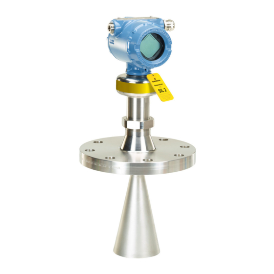
PRELIMINARY Reference Manual Transmitter Overview 00809-0100-4408, Rev AA November 2016 Components of the transmitter Figure 2-2 shows the different components of the transmitter. There are different antenna types and sizes available for various applications. Figure 2-2. Components ±15° Terminal compartment LCD display (optional) Transmitter housing (aluminum or stainless steel) Alignment marker (one per side) -
Page 20: System Integration
Intelligent Device Manager, or any other Device Descriptor (DD) or Field Device Integration (FDI) compatible host system. The Rosemount 5408 and 5408:SIS are compliant to the NAMUR NE 107 Field Diagnostics for standardized device diagnostic information. Figure 2-3. System Architecture... -
Page 21: Safety Messages
PRELIMINARY Reference Manual Mechanical Installation 00809-0100-4408, Rev AA November 2016 Section 3 Mechanical Installation Safety messages ............page 9 Review mounting considerations . -
Page 22: Review Mounting Considerations
PRELIMINARY Mechanical Installation Reference Manual November 2016 00809-0100-4408, Rev AA Review mounting considerations Before installing the transmitter, consider recommendations for mounting position, sufficient free space, nozzle requirements, etc. 3.2.1 Mounting position When finding an appropriate location on the tank for the transmitter, the conditions of the tank must be carefully considered. -
Page 23: Antenna Size
PRELIMINARY Reference Manual Mechanical Installation 00809-0100-4408, Rev AA November 2016 3.2.2 Antenna size Choose as large antenna diameter as possible. A larger receiving area concentrates the radar beam and ensures maximum antenna gain. Increased antenna gain permits greater margin for weak surface echoes. In addition, a larger antenna results in a smaller beam angle and thereby, less interference from any internal structures in the tank. -
Page 24: Beam Width And Beam Angle
PRELIMINARY Mechanical Installation Reference Manual November 2016 00809-0100-4408, Rev AA 3.2.5 Beam width and beam angle The transmitter should be mounted with as few internal structures as possible within the signal beam. Refer to Table 3-1 for beam angle and Table 3-2 for beam width at different distances. -
Page 25: Nozzle Requirements
PRELIMINARY Reference Manual Mechanical Installation 00809-0100-4408, Rev AA November 2016 3.2.6 Nozzle requirements In order to allow the microwaves to propagate undisturbed, the nozzle dimensions should be kept within the specified limits as given in Table 3-3 Table 3-4. Cone antenna For best performance, the cone antenna should extend at least 0.4 in. - Page 26 PRELIMINARY Mechanical Installation Reference Manual November 2016 00809-0100-4408, Rev AA Parabolic antenna Table 3-4 for nozzle height recommendations at different inclination angle. Figure 3-5. Mounting of the Parabolic Antenna Nozzle mounting Flange mounting in manhole cover Table 3-4. Nozzle Requirements for Parabolic Antenna Nozzle size (D) Inclination Maximum nozzle height (H),...
-
Page 27: Free Space Requirements
PRELIMINARY Reference Manual Mechanical Installation 00809-0100-4408, Rev AA November 2016 3.2.7 Free space requirements If the transmitter is mounted close to a wall or other tank obstructions such as heating coils and ladders, noise might appear in the measurement signal. Therefore the following minimum clearance, according to Table 3-5, must be maintained. -
Page 28: Installation In Still Pipe/Chamber
Max. 0.2 in. (5 mm) Max. 1° Level = 100% Pipe diameter (D) Min. 0.25 in. (6 mm) Max. D/10 Min. 6 in. (150 mm) Level = 0% For guidelines on slotted pipes, consult your local Emerson Automation Solutions representative. Mechanical Installation... -
Page 29: Ball Valve Installation
PRELIMINARY Reference Manual Mechanical Installation 00809-0100-4408, Rev AA November 2016 Consider the following chamber requirements: Pipes should be an all-metal material. Pipe should have a constant inside diameter. Inlet pipes should not protrude into the inside of the stand pipe. The inner surface must be smooth and clear of any rough edges. -
Page 30: Review Mounting Preparations
PRELIMINARY Mechanical Installation Reference Manual November 2016 00809-0100-4408, Rev AA Review mounting preparations 3.3.1 Assemble the segmented cone antenna This section applies to the segmented cone antenna (option code S2). Use only one segment; the total antenna length should not exceed 47.2 in. (1200 mm). To determine the antenna length, follow the guidelines in section “Nozzle requirements”... - Page 31 PRELIMINARY Reference Manual Mechanical Installation 00809-0100-4408, Rev AA November 2016 Secure the segment to the antenna. Measure the Antenna Extension Length (L). Update the transmitter configuration to the new Antenna Extension Length (L). Rosemount Radar Master: AMS Device Manager and Field Communicator: Under Configure, select Level Setup >...
-
Page 32: Shorten The Extended Cone Antenna
PRELIMINARY Mechanical Installation Reference Manual November 2016 00809-0100-4408, Rev AA 3.3.2 Shorten the extended cone antenna This section only applies to the extended cone antenna (option code S1). To determine the antenna length, follow the guidelines in section “Nozzle requirements” on page Mark where to cut the antenna. -
Page 33: Mount The Cone Antenna
PRELIMINARY Reference Manual Mechanical Installation 00809-0100-4408, Rev AA November 2016 Mount the cone antenna Figure 3-9. Overview Flanged version Flanged version with air purge ring (see page (see page Threaded version, D Threaded version, D > < (see page (see page Bracket mounting (see... -
Page 34: Flanged Version
PRELIMINARY Mechanical Installation Reference Manual November 2016 00809-0100-4408, Rev AA 3.4.1 Flanged version Lower transmitter with antenna and flange into the nozzle. Gasket Tighten bolts and nuts with sufficient torque for the flange and gasket choice. Align the transmitter head (see page 34). -
Page 35: Flanged Version With Air Purge Ring
PRELIMINARY Reference Manual Mechanical Installation 00809-0100-4408, Rev AA November 2016 3.4.2 Flanged version with air purge ring Place a suitable gasket on the tank flange. Place the purge ring over the gasket. Place a suitable gasket over the purge ring. Lower transmitter with antenna and flange into the nozzle. - Page 36 PRELIMINARY Mechanical Installation Reference Manual November 2016 00809-0100-4408, Rev AA Tighten bolts and nuts with sufficient torque for the flange and gasket choice. 1.0 in. (25.5 mm) Connect the air purging system. Use thread sealant or suitable gasket according to your site procedures. G3/8"...
-
Page 37: Threaded Version
PRELIMINARY Reference Manual Mechanical Installation 00809-0100-4408, Rev AA November 2016 3.4.3 Threaded version Antenna diameter (D) < Thread diameter (d) Flanged tank connection Place a suitable gasket on the tank flange. Place the customer supplied flange over the gasket. Tighten the bolts and nuts with sufficient torque for the flange and gasket choice. Apply anti-seize paste or PTFE tape on threads according to your site procedures. - Page 38 PRELIMINARY Mechanical Installation Reference Manual November 2016 00809-0100-4408, Rev AA Lower transmitter with antenna and flange into the nozzle. Gasket (for 1½-in. and 2-in. BSPP (G) threads only) Align the transmitter head (see page 34). Mechanical Installation...
- Page 39 PRELIMINARY Reference Manual Mechanical Installation 00809-0100-4408, Rev AA November 2016 Threaded tank connection Apply anti-seize paste or PTFE tape on threads according to your site procedures. Gasket may be used as a sealant for adapters with 1½ or 2-in. BSPP (G) threads. Mount the transmitter on tank.
- Page 40 PRELIMINARY Mechanical Installation Reference Manual November 2016 00809-0100-4408, Rev AA Antenna diameter (D) > Thread diameter (d) Unscrew and remove the antenna. H2 mm Note Do not scratch the microwave launcher. The microwave launcher is sensitive to mechanical impacts. Microwave launcher Apply anti-seize paste or PTFE tape on threads according to your site procedures.
- Page 41 PRELIMINARY Reference Manual Mechanical Installation 00809-0100-4408, Rev AA November 2016 Mount the adapter on the customer supplied flange. Gasket (for 1½-in. and 2-in. BSPP (G) threads only) Mount the antenna. Torque 20 in-lb (2 Nm) H2 mm Torque 250 in-lb (28 Nm) 38 mm Note Visually inspect the microwave launcher for damage and dirt.
- Page 42 PRELIMINARY Mechanical Installation Reference Manual November 2016 00809-0100-4408, Rev AA Lower transmitter with antenna and flange into the nozzle. Gasket Tighten the bolts and nuts with sufficient torque for the flange and gasket choice. Screw the adapter until it is properly tightened. Align the transmitter head (see page 34).
-
Page 43: Bracket Mounting
PRELIMINARY Reference Manual Mechanical Installation 00809-0100-4408, Rev AA November 2016 3.4.4 Bracket mounting Mount the bracket to the pipe/wall. On pipe: Horizontal pipe Vertical pipe On wall: Use screws suitable for the purpose Mount the holder to the bracket. Mechanical Installation... - Page 44 PRELIMINARY Mechanical Installation Reference Manual November 2016 00809-0100-4408, Rev AA Unscrew and remove the antenna. H2 mm Note Do not scratch the microwave launcher. The microwave launcher is sensitive to mechanical impacts. Microwave launcher Screw the transmitter into the holder. Mechanical Installation...
- Page 45 PRELIMINARY Reference Manual Mechanical Installation 00809-0100-4408, Rev AA November 2016 Mount the antenna. Torque 20 in-lb (2 Nm) H2 mm Torque 250 in-lb (28 Nm) 38 mm Align the transmitter head (see page 34). Mechanical Installation...
- Page 46 PRELIMINARY Mechanical Installation Reference Manual November 2016 00809-0100-4408, Rev AA 3.4.5 Align transmitter head Open tank Align the marking on sensor module either toward or along the tank wall. Still pipe Align the external ground screw toward the holes of the still pipe. Chamber Align the external ground screw toward the process connections.
- Page 47 PRELIMINARY Reference Manual Mechanical Installation 00809-0100-4408, Rev AA November 2016 Procedure Loosen the nut slightly and turn the transmitter. Verify the transmitter head is properly aligned (see page 52 for direction). Tighten the nut. Torque 355 in-lb (40 Nm) 60 mm Mechanical Installation...
-
Page 48: Overview
PRELIMINARY Mechanical Installation Reference Manual November 2016 00809-0100-4408, Rev AA Mount the parabolic antenna Figure 3-10. Overview Flanged version (see page Threaded version (see page Welded version (see page Mechanical Installation... -
Page 49: Installation
PRELIMINARY Reference Manual Mechanical Installation 00809-0100-4408, Rev AA November 2016 3.5.1 Flanged version Lower the flange and antenna assembly into the nozzle. Gasket Tighten the bolts and nuts with sufficient torque for the flange and gasket choice. Adjust the inclination of the antenna (see page 48). - Page 50 PRELIMINARY Mechanical Installation Reference Manual November 2016 00809-0100-4408, Rev AA 3.5.2 Threaded version Figure 3-11. Components A. Antenna B. Purge plug kit (optional with order) P/N 05400-1200-0001 C. Threaded sleeve D. M20 adapter E. Lock nut G 3½" (optional with order) P/N 05400-1200-0002 F.
- Page 51 PRELIMINARY Reference Manual Mechanical Installation 00809-0100-4408, Rev AA November 2016 Procedure Remove the lock nut (if applicable). Mount the O-ring. Mount the antenna adapter on flange/manhole cover. Ensure the antenna adapter fits tightly to the flange/manhole cover. Ø 3.98 ± 0.02 in. (Ø...
- Page 52 PRELIMINARY Mechanical Installation Reference Manual November 2016 00809-0100-4408, Rev AA Remove the M20 adapter and visually inspect the O-rings for damage and dirt. O-rings Carefully insert the antenna. Secure the antenna. Torque 180 in-lb (20 Nm) 27 mm Tighten the set screw. Torque 5 in-lb (0.5 Nm) H2 mm Mechanical Installation...
- Page 53 PRELIMINARY Reference Manual Mechanical Installation 00809-0100-4408, Rev AA November 2016 Lower the antenna assembly into the tank. Gasket Tighten the bolts and nuts with sufficient torque for the flange and gasket choice. Adjust the inclination of the antenna (see page 48).
- Page 54 PRELIMINARY Mechanical Installation Reference Manual November 2016 00809-0100-4408, Rev AA 3.5.3 Welded version Figure 3-12. Components A. Antenna B. Purge plug kit (optional with order) P/N 05400-1200-0001 C. Threaded sleeve D. M20 adapter E. Weld protection plate F. Flange ball G.
- Page 55 PRELIMINARY Reference Manual Mechanical Installation 00809-0100-4408, Rev AA November 2016 Procedure Mount the protection plates to flange/manhole cover. These plates protects the internal surfaces of the flange ball from dust and sparks during welding. Ø 3.94 ± 0.02 in. (Ø 100 ± 0.5 mm) Max.
- Page 56 PRELIMINARY Mechanical Installation Reference Manual November 2016 00809-0100-4408, Rev AA Weld the flange ball. Remove the protection plates and visually inspect the internal surfaces of the flange ball for damage and dirt. Mount the O-ring. Mechanical Installation...
- Page 57 PRELIMINARY Reference Manual Mechanical Installation 00809-0100-4408, Rev AA November 2016 Mount the ball joint. Insert the ball joint and place the clamp flange with the “7 Nm” marking side up. b. Gradually tighten the M8 screws. Torque 65 in-lb (7 Nm) H6 mm Remove the M20 adapter and visually inspect the O-rings for damage and dirt.
- Page 58 PRELIMINARY Mechanical Installation Reference Manual November 2016 00809-0100-4408, Rev AA Secure the antenna. Torque 180 in-lb (20 Nm) 27 mm Tighten the set screw. Torque 5 in-lb (0.5 Nm) H2 mm Lower the antenna assembly into the tank. Gasket Mechanical Installation...
- Page 59 PRELIMINARY Reference Manual Mechanical Installation 00809-0100-4408, Rev AA November 2016 Tighten the bolts and nuts with sufficient torque for the flange and gasket choice. Adjust the inclination of the antenna (see page 48). Connect the air purging system (see page 51).
- Page 60 PRELIMINARY Mechanical Installation Reference Manual November 2016 00809-0100-4408, Rev AA 3.5.4 Adjust the inclination of the antenna Contents may be under pressure. Do not loosen the M8 screws while in operation. Attempting to do so may release pressurized gases, resulting in serious injury or death. Loosen the M8 screws until the transmitter can rotate smoothly.
- Page 61 PRELIMINARY Reference Manual Mechanical Installation 00809-0100-4408, Rev AA November 2016 Adjust the inclination of the antenna. Gradually tighten the M8 screws. Torque 65 in-lb (7 Nm) H6 mm Remove the circular level. Mechanical Installation...
Need help?
Do you have a question about the Rosemount 5408 and is the answer not in the manual?
Questions and answers