Emerson Rosemount 5402 Reference Manual
Level transmitter, two-wire non-contacting radar
Hide thumbs
Also See for Rosemount 5402:
- Advanced user's manual (201 pages) ,
- Reference manual (314 pages)

Related Manuals for Emerson Rosemount 5402


Summary of Contents for Emerson Rosemount 5402
- Page 1 Reference Manual 00809-0100-4026, Rev KC October 2018 ™ Rosemount 5400 Level Transmitter Two-Wire Non-Contacting Radar...
-
Page 3: Table Of Contents
Reference Manual Contents 00809-0100-4026, Rev KC October 2018 Contents 1Section 1: Introduction Using this manual ..............1 Product recycling/disposal. - Page 4 Contents Reference Manual 00809-0100-4026, Rev KC October 2018 3.4.8 Adjust inclination of parabolic antenna ........63 3.4.9 Rod antenna with threaded connection.
- Page 5 ™ 4.13.3 Emerson Wireless THUM Adapter ......... . 98 5Section 5: Basic Configuration/Start-up Safety messages.
- Page 6 Contents Reference Manual 00809-0100-4026, Rev KC October 2018 5.9.2 Radar level transmitter - level value in percent (%)......144 5.10 Tri-Loop™...
- Page 7 Reference Manual Contents 00809-0100-4026, Rev KC October 2018 7.14.5 Measurement status............183 7.14.6 Volume calculation status .
- Page 8 Contents Reference Manual 00809-0100-4026, Rev KC October 2018 A.1.5 RS-485 with Modbus communication (output option code M) ....209 A.1.6 Display and configuration ........... 210 A.1.7 Diagnostics .
- Page 9 Reference Manual Contents 00809-0100-4026, Rev KC October 2018 B.16 Republic of Korea ............. . . 250 B.17 Combinations .
- Page 10 Contents Reference Manual 00809-0100-4026, Rev KC October 2018 EAppendix E: Level Transducer Block Overview ............... 281 E.1.1 Definition .
- Page 11 North American Response Center: Equipment service needs. 1-800-654-7768 (24 hours a day — includes Canada) For equipment service or support needs outside the United States, contact your local Emerson Automation Solutions representative. NOTICE There are no health hazards from the Rosemount 5400 Level Transmitter. The microwave power density in the tank is only a small fraction of the allowed power density according to international standards.
- Page 12 Title Page Reference Manual 00809-0100-4026, Rev KC October 2018 Failure to follow safe installation and service guidelines could result in death or serious injury. Make sure only qualified personnel perform the installation. Use the equipment only as specified in this manual. Failure to do so may impair the protection ...
- Page 13 Equipment ratings and certifications are no longer valid on any products that have been damaged or modified without the prior written permission of Emerson Automation Solutions. Any continued use of product that has been damaged or modified without the written authorization is at the customer’s sole risk and expense.
- Page 14 Reference Manual Title Page 00809-0100-4026, Rev KC October 2018 Title Page...
-
Page 15: Using This Manual
Reference Manual Introduction 00809-0100-4026, Rev KC October 2018 Section 1 Introduction Using this manual ™ This manual provides installation, configuration and maintenance information for the Rosemount 5400 Level Transmitter. Section 2: Transmitter Overview contains an introduction to theory of operation and a description of the transmitter. -
Page 16: Product Recycling/Disposal
Introduction Reference Manual 00809-0100-4026, Rev KC October 2018 Product recycling/disposal Recycling of equipment and packaging should be taken into consideration and disposed of in accordance with local and national legislation/regulations. Introduction... -
Page 17: Theory Of Operation
Reference Manual Introduction 00809-0100-4026, Rev KC October 2018 Section 2 Transmitter Overview Theory of operation ..............page 3 Application examples . -
Page 18: Application Examples
Introduction Reference Manual 00809-0100-4026, Rev KC October 2018 Application examples Tanks, vessels, and containers with calm surfaces Non-contacting radar can be used in less challenging applications, such as storage and buffer tanks: It is easy to mount, maintenance-free, and highly accurate ... - Page 19 Reference Manual Introduction 00809-0100-4026, Rev KC October 2018 Reactor vessels The innovative design of the Rosemount 5400 makes it an excellent choice for the most difficult applications, such as reactor vessels: Unique circular polarization provides greater mounting flexibility – no tank wall clearance distance is needed Direct measurement –...
-
Page 20: System Architecture
Introduction Reference Manual 00809-0100-4026, Rev KC October 2018 System architecture The Rosemount 5400 is loop-powered, and uses the same two wires for power supply and output signal. ® ™ The output is a 4-20 mA analog signal superimposed with a digital HART Fieldbus or OUNDATION ®... - Page 21 Host/DCS system (e.g. DeltaV) Configuration with RRM (hooked up on Fieldbus segment) Rosemount 5401 H2 - High speed field bus Rosemount 5402 H1 - Low speed field bus Rosemount 5601 Fieldbus modem The RS-485 Modbus version communicates by Modbus RTU, Modbus ASCII, and Level Master Protocols.
-
Page 22: Process Characteristics
Introduction Reference Manual 00809-0100-4026, Rev KC October 2018 Process characteristics Dielectric constant A key parameter for measurement performance is reflectivity. A high dielectric constant of the media provides better reflection and enables a longer measuring range. Foam Rosemount 5400 Series Radar Transmitter measurement in foamy applications depends on the foam properties;... - Page 23 There is often a lot of dust during the fill cycle. The dielectric value of many solids is fairly low. See Table 2-1 on page 9 for common solids characteristics. For solids applications, the high frequency version Rosemount 5402 with 4-in. (101.6 mm) cone or parabolic antenna is available. Table 2-1. Sample Solids Applications Common characteristics...
-
Page 24: Components Of The Transmitter
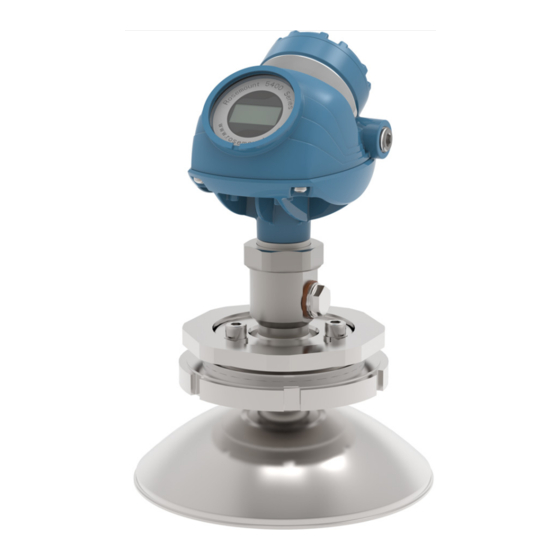
Introduction Reference Manual 00809-0100-4026, Rev KC October 2018 Components of the transmitter The Rosemount 5400 is available with a die-cast aluminum or stainless steel (SST) housing containing advanced electronics for signal processing. The radar electronics produces an electromagnetic pulse that is emitted through the antenna. There are different antenna types and sizes available for various applications. -
Page 25: Antenna Selection Guide/Measuring Range
Alcohols, concentrated acids, organic solvents, oil/water mixtures, and acetone ( = 4.0-10.0). Conductive liquids, e.g. water based solutions, dilute acids, and alkalis ( > 10.0). Table 2-2. Rosemount 5402, Maximum Recommended Measuring Range, ft (m) High-frequency antennas Dielectric constant 2-in. (50.8 mm) - Page 26 Introduction Reference Manual 00809-0100-4026, Rev KC October 2018 Table 2-3. Rosemount 5401, Maximum Recommended Measuring Range, ft (m) Frequency Antennas Dielectric Constant 3-in. Cone (25) (35) (35) 4-in. (12) (15) (25) (35) (35) (12) Cone/Rod 6-in. Cone (13) (20) (25) (25) (35) (35)
- Page 27 Parabolic Cone (preferred) model and antenna to select, depending on application. G = Good AD = Application Dependent (contact your local Emerson Automation Solution representative) NR = Not Recommended Best choice for a Ideal for small tanks Only for solids...
- Page 28 Coating/viscous/crystallizing liquids Solids, granules, powders The obstruction should not be within the radar beam. Preferred choices due to more narrow radar beam: Rosemount 5402, and cone antenna. If tall nozzle, use extended antenna. The active part must protrude beneath the nozzle.
-
Page 29: Safety Messages
Reference Manual Mechanical Installation 00809-0100-4026, Rev KC October 2018 Section 3 Mechanical Installation Safety messages ..............page 15 Installation procedure . - Page 30 Equipment ratings and certifications are no longer valid on any products that have been damaged or modified without the prior written permission of Emerson™ Automation Solutions. Any continued use of product that has been damaged or modified without prior written authorization is at the customer's sole risk and expense.
-
Page 31: Installation Procedure
Reference Manual Mechanical Installation 00809-0100-4026, Rev KC October 2018 Installation procedure Follow these steps for proper installation: Review installation considerations. Mount the transmitter (see page 35). Wire the transmitter (see page 71). Ground the housing (see page 73). Make sure covers and cable/conduit connections are tight. -
Page 32: Mounting Considerations
Mechanical Installation Reference Manual 00809-0100-4026, Rev KC October 2018 Mounting considerations Before installing a Rosemount 5400, consider specific mounting requirements, vessel, and process char- acteristics. 3.3.1 Mounting location For optimal performance, the transmitter should be installed in locations with a clear and unobstructed view of the level surface (A): Filling inlets creating turbulence (B), and stationary metallic objects with horizontal surfaces (C) ... - Page 33 Reference Manual Mechanical Installation 00809-0100-4026, Rev KC October 2018 A metal still-pipe can be used to avoid disturbing objects, turbulence, and foam (G). Figure 3-2. Mounting in Still-Pipe The walls in non-metallic tanks are invisible to the radar signal, so nearby objects outside of the tank ...
-
Page 34: Special Considerations In Solids Applications
Mechanical Installation Reference Manual 00809-0100-4026, Rev KC October 2018 3.3.2 Special considerations in solids applications The transmitter should be mounted as close to the center of the tank as possible, but not in the center of the tank. A general practice is to mount the transmitter at tank radius from the tank wall, see Figure 3-4. -
Page 35: Mounting In Pipes
Reference Manual Mechanical Installation 00809-0100-4026, Rev KC October 2018 3.3.3 Mounting in pipes Still-pipe mounting is recommended for tanks with extremely turbulent surface conditions. All cone antenna sizes for the Rosemount 5400 can be used for still-pipe installations. The 3-in. (75 mm) antenna for the Rosemount 5401 is designed for use in still-pipes only. -
Page 36: Condensation Conditions
Mechanical Installation Reference Manual 00809-0100-4026, Rev KC October 2018 Figure 3-7. Recommended Hole Size for Pipe Installations min. 6 in. (150 mm) max. Ø: D/10. 3.3.4 Condensation conditions Generally, the radar signal is unaffected by condensation and low pressure steam. If affected, the lower microwave frequencies are less affected. -
Page 37: Nozzle Considerations
The flange on the tank should have a flat or raised face. Other tank flanges may be possible, contact your local Emerson Automation Solutions representative for advice. Figure 3-10. Nozzle Considerations for Rosemount 5402 with Process Seal Antenna (K) Bad welding... - Page 38 8 in. (200 mm) for 10-in. pipe sch std Disturbing objects inside the nozzle (M) may impact the measurement, and should be avoided. Figure 3-11. Nozzle Considerations for Rosemount 5402 with Parabolic Antenna (M) Bad welding Rosemount 5401 with cone antenna The antenna should extend 0.4 in.
- Page 39 Still-pipes in metallic materials If used correctly, pipe measurement can be advantageous in many applications. The Rosemount 5402 is the preferred choice for smaller pipe diameters. Use the Rosemount 5401 for larger pipe diameters (6-8 in./150-200 mm), ...
- Page 40 00809-0100-4026, Rev KC October 2018 Ball-valve installation The Rosemount 5400 can be isolated from the process by using a valve. The Rosemount 5402 is the preferred choice for long nozzle measurement. Use the largest possible antenna. Use a full-port ball valve.
-
Page 41: Nozzle Recommendations And Requirements
Cone 8 in. (200 mm) Alloy C-276, Alloy 400 10.2 (260) 7.6 (193) For Rosemount 5402, the values for maximum nozzle height are recommendations. Note that the Rosemount 5402 with cone antenna can be recessed in smooth nozzles up to 6 ft (2m). Mechanical Installation... - Page 42 Process Seal 4 in. (100 mm) 19.7 (500) 4.0 (102) For Rosemount 5402, the values for maximum nozzle height are recommendations. Note that the Rosemount 5402 with process seal antenna can be recessed in smooth nozzles up to 6 ft (2m). Mechanical Installation...
- Page 43 0.6 (15) Pipe sch std, Ø10 in. (250 mm) 0° 8.0 (200) 3° 8.0 (200) 6° 8.0 (200) 9° 8.0 (200) 12° 5.9 (150) 15° 4.3 (110) For Rosemount 5402, the values for maximum nozzle height are recommendations. Mechanical Installation...
- Page 44 For Rosemount 5402, the values for maximum nozzle height are recommendations. The extended cone antennas are available in 5 in. (125 mm) step increments from 10 to 50 in. (250-1250 mm). Contact your local Emerson Automation Solutions representative for more information. Expect long lead times for sizes other than the 20 in. (500 mm) version.
-
Page 45: Service Space
Reference Manual Mechanical Installation 00809-0100-4026, Rev KC October 2018 3.3.7 Service space For easy access to the transmitter, mount it with sufficient service space. There is no requirement on clearance distance from the tank wall, provided it is flat and free of obstructions such as heating coils and ladders. -
Page 46: Beam Width
33 ft (10 m) 49 ft (15 m) 66 ft (20 m) Beamwidth Table 3-6. Beam Width for the Rosemount 5402 Model (in ft [m]) Antenna 4 in. (DN 100) 2 in. (DN 50) cone/ 3 in. (DN 80) cone/... - Page 47 41 (12.5) 26.2 (8.0) 19.7 (6.0) 66 ft (20 m) Figure 3-22. Beam Angle Beam angle Table 3-8. Beam Angle for the Rosemount 5402 Antenna Beam angle 2 in. (50 mm) cone/process seal 19° 3 in. (75 mm) cone/process seal 14°...
-
Page 48: Vessel Characteristics
The Rosemount 5400 can be isolated from the process by using a valve. Use a full-port ball valve. The Rosemount 5402 is the required and the process seal antenna is the preferred choice, since it does not require a spool piece. The cone antenna can also be used. -
Page 49: Mounting
Reference Manual Mechanical Installation 00809-0100-4026, Rev KC October 2018 Mounting Mount the transmitter on a nozzle on top of the tank making sure only qualified personnel perform the installation. The transmitter housing must not be opened. If the transmitter housing must be removed for service, make sure the PTFE sealing is carefully protected against dust and water. -
Page 50: Cone Antenna With Threaded Tank Connection
Mechanical Installation Reference Manual 00809-0100-4026, Rev KC October 2018 3.4.2 Cone antenna with threaded tank connection 1. Seal and protect threads. Use anti-seize paste or PTFE tape according to your site procedures. 2. Lower the device into the tank. 3. Screw the adapter into the process connection. Mechanical Installation... - Page 51 Reference Manual Mechanical Installation 00809-0100-4026, Rev KC October 2018 4. Rotate the transmitter head so the cable entries/display face the desired direction. Torque 30 Lbft (40 Nm) Mechanical Installation...
-
Page 52: Cone Antenna With Threaded Tank Connection And Customer Supplied Flange
Mechanical Installation Reference Manual 00809-0100-4026, Rev KC October 2018 3.4.3 Cone antenna with threaded tank connection and customer supplied flange Antenna diameter (D) ≤ Flange hole diameter (d) 1. Place a gasket on the tank flange. Gasket 2. Place the customer supplied flange over the gasket. 3. - Page 53 Reference Manual Mechanical Installation 00809-0100-4026, Rev KC October 2018 4. Seal and protect threads. Use anti-seize paste or PTFE tape according to your site procedures. 5. Lower the device into the tank. 6. Screw the adapter into the process connection. Mechanical Installation...
- Page 54 Mechanical Installation Reference Manual 00809-0100-4026, Rev KC October 2018 7. Rotate the transmitter head so the cable entries/display face the desired direction. Torque 30 Lbft (40 Nm) Antenna diameter (D) > Flange hole diameter (d) 1. Place the device on a workbench. 2.
- Page 55 Reference Manual Mechanical Installation 00809-0100-4026, Rev KC October 2018 Note Handle the adapter carefully to prevent damage to the PTFE seal. High-frequency version Low-frequency version 3. Insert the six M4 screws and tighten them two to three turns. Note After pre-mounting the screws, make sure to finish the installation procedure immediately. The screws come with pre-applied threadlocker, designed for permanent locking.
- Page 56 Mechanical Installation Reference Manual 00809-0100-4026, Rev KC October 2018 5. Place the customer supplied flange on the tank flange. 6. Tighten the adapter by hand. 7. Flip the flange over. Mechanical Installation...
- Page 57 Reference Manual Mechanical Installation 00809-0100-4026, Rev KC October 2018 8. Fit the antenna onto the adapter and tighten the six M4 screws. 9. Carefully lift the antenna and flange assembly. 10.Place a gasket on the tank flange. Gasket Mechanical Installation...
- Page 58 Mechanical Installation Reference Manual 00809-0100-4026, Rev KC October 2018 11.Lower the antenna and flange assembly into the tank. 12.Tighten the bolts and nuts with sufficient torque for the flange and gasket choice. 13.Screw the adapter until it is properly tightened. Mechanical Installation...
- Page 59 Reference Manual Mechanical Installation 00809-0100-4026, Rev KC October 2018 14.Mount the transmitter head and tighten the nut (torque 30 Lbft, 40 Nm). Mechanical Installation...
-
Page 60: Process Seal Antenna With Flange
Mechanical Installation Reference Manual 00809-0100-4026, Rev KC October 2018 3.4.4 Process seal antenna with flange 1. Place antenna on top of the nozzle and mount flange. 2. Tighten bolts cross-wise. For torque information, see Table 3-10 on page The mounting information applies to the updated Process Seal antenna design, released in February 2012. Antennas manufactured before this date have wetted O-rings and require a different installation procedure. - Page 61 Reference Manual Mechanical Installation 00809-0100-4026, Rev KC October 2018 Table 3-10. Torque Information Torque Process seal flange (Nm) (Lbft) 2 in., 150 lb. 2 in., 300 lb. 3 in., 150 lb. 3 in., 300 lb. 4 in., 150 lb. 4 in., 300 lb. DN 50 PN 40 DN 80 PN 40 DN 100 PN 16...
-
Page 62: Parabolic Antenna With Flange
Mechanical Installation Reference Manual 00809-0100-4026, Rev KC October 2018 3.4.5 Parabolic antenna with flange 1. Mount antenna assembly on tank. Gasket 2. Adjust inclination of antenna. “Adjust inclination of parabolic antenna” on page 63 for further information. Mechanical Installation... - Page 63 Reference Manual Mechanical Installation 00809-0100-4026, Rev KC October 2018 3. Tighten blind plug or install air purging system. Air purging? Use thread sealant or Torque 180 in-lb (20 Nm) gasket according to your site procedures. G3/8" 0.3-0.4 in. (8-10 mm) (gasket excluded) Mechanical Installation...
-
Page 64: Parabolic Antenna With Welded Connection
Mechanical Installation Reference Manual 00809-0100-4026, Rev KC October 2018 3.4.6 Parabolic antenna with welded connection Figure 3-23. Components Weld protection plate Washer M20 adapter Weld protection bar M8 screw G3/8" bonded seal Flange ball Antenna Blind plug O-ring Ball joint Clamp flange Threaded sleeve Mechanical Installation... - Page 65 Reference Manual Mechanical Installation 00809-0100-4026, Rev KC October 2018 1. Mount protection plates to flange/manhole cover. These plates protects the internal surfaces of the flange ball from welding sparks. Ø 3.94 ± 0.02 in. (Ø 100 ± 0.5 mm) Max. 1.18 in. (30 mm) Mechanical Installation...
- Page 66 Mechanical Installation Reference Manual 00809-0100-4026, Rev KC October 2018 2. Weld flange ball. 3. Remove protection plates. Visually inspect the internal surfaces of the flange ball for damage and dirt. 4. Mount O-ring. Mechanical Installation...
- Page 67 Reference Manual Mechanical Installation 00809-0100-4026, Rev KC October 2018 5. Mount ball joint. Gradually tighten the M8 nuts. Torque 90 in-lb (10 Nm) 6. Remove protection cap. Visually inspect the O-rings for damage and dirt. O-rings Mechanical Installation...
- Page 68 Mechanical Installation Reference Manual 00809-0100-4026, Rev KC October 2018 7. Carefully insert antenna. 8. Secure antenna. Torque 180 in-lb (20 Nm) Mechanical Installation...
- Page 69 Reference Manual Mechanical Installation 00809-0100-4026, Rev KC October 2018 9. Tighten set screw.Mount antenna assembly on tank. Torque 5 in-lb (0.5 Nm) 10. Mount antenna assembly on tank. Gasket 11. Adjust inclination of antenna. “Adjust inclination of parabolic antenna” on page 63 for further information.
- Page 70 Mechanical Installation Reference Manual 00809-0100-4026, Rev KC October 2018 12. Tighten blind plug or install air purging system. Air purging? Use thread sealant or Torque 180 in-lb (20 Nm) gasket according to your site procedures. G3/8" 0.3-0.4 in. (8-10 mm) (gasket excluded) Mechanical Installation...
-
Page 71: Parabolic Antenna With Threaded Connection
Reference Manual Mechanical Installation 00809-0100-4026, Rev KC October 2018 3.4.7 Parabolic antenna with threaded connection Figure 3-24. Components Lock nut Antenna G3/8" bonded seal Antenna adapter with ball joint Threaded sleeve Blind plug O-ring M20 adapter Mechanical Installation... - Page 72 Mechanical Installation Reference Manual 00809-0100-4026, Rev KC October 2018 1. Remove lock nut. 2. Mount O-ring. 3. Mount antenna adapter on flange/manhole cover. Mechanical Installation...
- Page 73 Reference Manual Mechanical Installation 00809-0100-4026, Rev KC October 2018 Make sure the antenna adapter fits tightly to the flange/manhole cover. Ø 3.98 ± 0.02 in. (Ø 101 ± 0.6 mm) G3½" Max. 1.18 in. (30 mm) > 0.59 in. (15 mm) 4.
- Page 74 Mechanical Installation Reference Manual 00809-0100-4026, Rev KC October 2018 5. Carefully insert antenna. 6. Secure antenna. Torque 180 in-lb (20 Nm) Mechanical Installation...
- Page 75 Reference Manual Mechanical Installation 00809-0100-4026, Rev KC October 2018 7. Tighten set screw. Torque 5 in-lb (0.5 Nm) 8. Mount antenna assembly on tank. Gasket 9. Adjust the inclination of the antenna. See section “Adjust inclination of parabolic antenna” on page 63 for further information.
- Page 76 Mechanical Installation Reference Manual 00809-0100-4026, Rev KC October 2018 10.Tighten blind plug or install air purging system. Air purging? Use thread sealant or Torque 180 in-lb (20 Nm) gasket according to your site procedures. G3/8" 0.3-0.4 in. (8-10 mm) (gasket excluded) Mechanical Installation...
-
Page 77: Adjust Inclination Of Parabolic Antenna
Reference Manual Mechanical Installation 00809-0100-4026, Rev KC October 2018 3.4.8 Adjust inclination of parabolic antenna Orientation General best practice is to initially align the parabolic antenna vertically to the ground. 90° If the surface echo is weak, a small inclination of the antenna toward the surface slope may improve ... - Page 78 Mechanical Installation Reference Manual 00809-0100-4026, Rev KC October 2018 Procedure 1. Remove transmitter housing (if applicable). 2. Loosen M8 screws until antenna can tilt smoothly. Contents may be under pressure. Do not loosen the M8 screws while in operation. Attempting to do so may release pressurized gases, resulting in serious injury or death.
- Page 79 Reference Manual Mechanical Installation 00809-0100-4026, Rev KC October 2018 4. Adjust inclination of antenna. 5. Gradually tighten M8 screws. Torque 90 in-lb (10 Nm) Mechanical Installation...
- Page 80 Mechanical Installation Reference Manual 00809-0100-4026, Rev KC October 2018 6. Remove circular level. 7. Mount transmitter housing. Torque 355 in-lb (40 Nm) Mechanical Installation...
-
Page 81: Rod Antenna With Threaded Connection
Reference Manual Mechanical Installation 00809-0100-4026, Rev KC October 2018 3.4.9 Rod antenna with threaded connection 1. Lower transmitter with antenna into the tank. Tank connections with NPT threads require a sealant for pressure-tight joints. 2. Turn tank seal adapter until properly secured in the process connection. 3. -
Page 82: Rod Antenna With Flanged Connection
Mechanical Installation Reference Manual 00809-0100-4026, Rev KC October 2018 3.4.10 Rod antenna with flanged connection 1. Lower transmitter with antenna and flange into the tank nozzle. Gasket 2. Tighten bolts and nuts with sufficient torque for the flange and gasket choice. 3. -
Page 83: Tri Clamp Tank Connection
Reference Manual Mechanical Installation 00809-0100-4026, Rev KC October 2018 3.4.11 Tri Clamp tank connection 1. Lower transmitter with antenna into the tank. Gasket 2. Fasten Tri Clamp to the tank with a clamp. 3. Adjust display orientation (optional). Torque 30 Lbft (40 Nm) Mechanical Installation... -
Page 84: Bracket Mounting
Mechanical Installation Reference Manual 00809-0100-4026, Rev KC October 2018 3.4.12 Bracket mounting 1. Mount bracket to the pipe/wall. On pipe: Horizontal pipe Vertical pipe On wall: Use screws suitable for the purpose 2. Mount transmitter with antenna to the bracket. Mechanical Installation... -
Page 85: Safety Messages
Reference Manual Electrical Installation 00809-0100-4026, Rev KC October 2018 Section 4 Electrical Installation Safety messages ..............page 71 Wiring and power supply requirements . - Page 86 Operation and Maintenance Reference Manual 00809-0100-4026, Rev KC October 2018 Failure to follow safe installation and service guidelines could result in death or serious injury. Make sure only qualified personnel perform installation or service. Use the equipment only as specified in this manual. Failure to do so may impair the protection ...
-
Page 87: Wiring And Power Supply Requirements
Reference Manual Electrical Installation 00809-0100-4026, Rev KC October 2018 Wiring and power supply requirements Wiring and power supply requirements can be dependent upon the approval certification. As with all ™ Fieldbus requirements, a conditioned power supply and terminating resistors are required OUNDATION for proper operation. -
Page 88: Cable Selection
Operation and Maintenance Reference Manual 00809-0100-4026, Rev KC October 2018 Note In the explosion-proof/flameproof version, the electronics is grounded via the transmitter housing. After installation and commissioning make sure that no ground currents exist due to high ground potential differences in the installation. Cable selection Use shielded twisted pair wiring for the Rosemount 5400 to comply with EMC regulations. -
Page 89: Connecting The Transmitter
Reference Manual Electrical Installation 00809-0100-4026, Rev KC October 2018 Connecting the transmitter 1. Make sure the power supply is switched off. 2. Remove the terminal block cover. 3. Remove the plastic plugs. 4. Pull the cable through cable gland/conduit. Adapters are required if M20 glands are used. 5. - Page 90 Operation and Maintenance Reference Manual 00809-0100-4026, Rev KC October 2018 6. Seal any unused port with enclosed metal plug. Note Apply PTFE tape or other sealant to the threads. 7. Tighten the cable glands. Note Apply PTFE tape or other sealant to the threads. Note Make sure to arrange the wiring with a drip loop.
- Page 91 Reference Manual Electrical Installation 00809-0100-4026, Rev KC October 2018 8. Mount the cover so it is secure to meet explosion-proof requirements. 9. For ATEX, IECEx, NEPSI, INMETRO, and TIIS installations, lock the cover with the locking screw. 10.Connect the power supply. Electrical Installation...
-
Page 92: Hart ® Communication
Operation and Maintenance Reference Manual 00809-0100-4026, Rev KC October 2018 ® HART communication 4.9.1 Power requirements The Rosemount 5400 Series transmitter operates with a power supply ranging from 16 - 42.4 Vdc (16 - 30 Vdc in IS applications, 20 - 42.4 Vdc in explosion-proof/flameproof applications and in non-sparking/energy-limited applications). - Page 93 Reference Manual Electrical Installation 00809-0100-4026, Rev KC October 2018 Figure 4-3. Intrinsically Safe Installations Maximum Load Resistance R() Operating region External Power Supply Voltage U Figure 4-4. Explosion-Proof/Flameproof Installations Maximum Load Resistance R() 1400 1200 1148 1000 Operating region 42.4 External Power Supply Voltage U Note For flameproof/explosion-proof installations, the diagram is only valid if the HART load resistance is at...
-
Page 94: Non-Intrinsically Safe Power Supply
Operation and Maintenance Reference Manual 00809-0100-4026, Rev KC October 2018 4.9.3 Non-intrinsically safe power supply With a non-intrinsically safe power supply in non-hazardous installations or explosion-proof/flameproof installations, wire the transmitter as shown in Figure 4-5. Note Make sure the power supply is off when connecting the transmitter. Figure 4-5. -
Page 95: Intrinsically Safe Power Supply
Reference Manual Electrical Installation 00809-0100-4026, Rev KC October 2018 4.9.4 Intrinsically safe power supply With an intrinsically safe power supply, wire the transmitter as shown in Figure 4-6. Note Make sure the instruments in the loop are installed according to intrinsically safe field wiring practices. Installation also needs to comply with the applicable installation/control drawing. -
Page 96: Type N Approvals: Non-Sparking/Energy-Limited Power Supply
Operation and Maintenance Reference Manual 00809-0100-4026, Rev KC October 2018 4.9.5 Type N approvals: non-sparking/energy-limited power supply With a non-sparking/energy- limited power supply, wire the transmitter as shown in Figure 4-7. Figure 4-7. Wiring Diagram for Non-Sparking/Energy-Limited Power Supply (HART) HART: U =42.4 V Rosemount 5400... -
Page 97: Foundation
Reference Manual Electrical Installation 00809-0100-4026, Rev KC October 2018 4.10 Fieldbus OUNDATION 4.10.1 Power requirements Terminals in the transmitter housing provide connections for signal wiring. The Rosemount 5400 is powered over F Fieldbus with standard fieldbus power supplies. OUNDATION The transmitter operates with the following power supplies: Approval type Power supply (Vdc) 9 - 30... - Page 98 Operation and Maintenance Reference Manual 00809-0100-4026, Rev KC October 2018 Connecting fieldbus devices Figure 4-9. Rosemount 5400 Field Wiring 6200 ft (1900 m) max Signal (The power supply, wiring filter, first terminator, and configuration tool are typically located in the control room.) Intrinsically safe installations may allow fewer devices per IS barrier due to current limitations.
-
Page 99: Non-Intrinsically Safe Power Supply
Reference Manual Electrical Installation 00809-0100-4026, Rev KC October 2018 4.10.2 Non-intrinsically safe power supply With non-intrinsically safe power supply in Non-hazardous installations or Explosion-proof/Flameproof installations, wire the transmitter as shown in Figure 4-10. Rosemount 5400 with Explosion-proof/Flameproof Output have a built-in barrier; no external barrier needed. -
Page 100: Intrinsically Safe Power Supply
Operation and Maintenance Reference Manual 00809-0100-4026, Rev KC October 2018 4.10.3 Intrinsically safe power supply When your power supply is intrinsically safe, wire the transmitter as shown in Figure 4-11. Note Make sure that the instruments in the loop are installed in accordance with intrinsically safe field wiring practices. -
Page 101: Type N Approvals: Non-Sparking/Energy-Limited Power Supply
Reference Manual Electrical Installation 00809-0100-4026, Rev KC October 2018 4.10.4 Type N approvals: non-sparking/energy-limited power supply With a non-sparking/energy-limited power supply, wire the transmitter as shown in Figure 4-12. Figure 4-12. Wiring Diagram for Non-Sparking/Energy-Limited Power Supply Fieldbus) OUNDATION Fieldbus: U = 32 V OUNDATION Rosemount 5400... -
Page 102: Hart To Modbus Converter (Hmc)
Operation and Maintenance Reference Manual 00809-0100-4026, Rev KC October 2018 4.11 HART to Modbus Converter (HMC) The Rosemount 5400 RS-485 with Modbus communication transmitter version operates using a power supply ranging from 8-30 Vdc (max. rating). See the Rosemount 5300/5400 Series with HART to Modbus Converter Manual Supplement for details. - Page 103 Reference Manual Electrical Installation 00809-0100-4026, Rev KC October 2018 Figure 4-13. Field Wiring Connections If it is the last transmitter on the bus, connect the 120 termination resistor. HART HART Power supply 120 RS-485 Bus 120 Electrical Installation...
-
Page 104: Connection Terminals
Operation and Maintenance Reference Manual 00809-0100-4026, Rev KC October 2018 4.11.2 Connection terminals The connection terminals are described in Table 4-2 below. Table 4-2. Connection Terminals Connector label Description Comment HART + Positive HART connector Connect to PC with RRM software, Field Communicator, or other HART configurators. -
Page 105: Bus
Reference Manual Electrical Installation 00809-0100-4026, Rev KC October 2018 4.11.3 RS-485 bus The Rosemount 5400 does not provide electrical isolation between the RS-485 bus and the transmitter power supply. Maintain a bus topology and minimize stub length. Figure 4-15 identifies multidrop wiring topology, where up to 32 devices may be wired on one RS-485 ... - Page 106 Operation and Maintenance Reference Manual 00809-0100-4026, Rev KC October 2018 Alternatively, the Rosemount 5400 can be installed as shown in Figure 4-16. If this wiring layout is used, there is an increased risk for communication disturbances due to differences in potential between grounding points.
-
Page 107: External Hart Devices (Slaves)
Reference Manual Electrical Installation 00809-0100-4026, Rev KC October 2018 4.11.5 External HART devices (slaves) The HMC supports up to four external HART devices. The external devices are separated by using the HART address. The address must be different between the external devices and only addresses 1 to 5 are allowed for multiple slaves. -
Page 108: Establish Hart Communication
Operation and Maintenance Reference Manual 00809-0100-4026, Rev KC October 2018 4.12 Establish HART communication The Rosemount 5400 can be configured using the RRM PC software or a Field Communicator. Configuration is done by sending HART commands through the HMC to the Rosemount 5400 electronics. - Page 109 Reference Manual Electrical Installation 00809-0100-4026, Rev KC October 2018 3. Enable HART communication and make sure the port for the RS-485 Converter is selected. Use the following settings: 4. Connect the power wires (or cycle power) to the transmitter. 5. Wait 20 seconds and then open the Search Device window in RRM (also see Note on page 96).
-
Page 110: Connect To The Hart Terminals
Operation and Maintenance Reference Manual 00809-0100-4026, Rev KC October 2018 Note Take the following into consideration if there are multiple Rosemount 5400 Modbus units on the bus: By default, the transmitters have HART address 1. It will not be possible to establish communication on HART address 1 if several transmitters have the same address. -
Page 111: Optional Devices
Reference Manual Electrical Installation 00809-0100-4026, Rev KC October 2018 4.13 Optional devices 4.13.1 Tri-Loop™ HART to analog converter The Rosemount 5400 outputs a HART signal with four process variables. The Model 333 HART Tri-Loop provides up to three additional analog 4-20 mA outputs. Figure 4-20. -
Page 112: Emerson ™ Wireless Thum ™ Adapter
Operation and Maintenance Reference Manual 00809-0100-4026, Rev KC October 2018 ™ ™ 4.13.3 Emerson Wireless THUM Adapter The Rosemount 5400 can be combined with the THUM Adapter. For more information, see the Wireless THUM Adapter Technical Note and the Reference Manual. -
Page 113: Safety Messages
Reference Manual Configuration 00809-0100-4026, Rev KC October 2018 Section 5 Basic Configuration/Start-up Safety messages ..............page 99 Overview . -
Page 114: Overview
Configuration Reference Manual 00809-0100-4026, Rev KC October 2018 Overview ™ The configuration of a Rosemount 5400 Level Transmitter is normally a simple and straightforward task. If the transmitter is pre-configured at the factory according to ordering specifications in the Configuration Data Sheet, no further basic configuration is required, unless tank conditions have changed. -
Page 115: Basic Configuration Parameters
Reference Manual Configuration 00809-0100-4026, Rev KC October 2018 Basic configuration parameters This chapter describes the basic parameters that need to be configured for a Rosemount 5400. If the transmitter is factory-configured according to the ordering specifications in the Configuration Data Sheet, no further basic configuration is needed unless conditions have changed since the ordering date. - Page 116 Configuration Reference Manual 00809-0100-4026, Rev KC October 2018 Figure 5-2. Upper Reference Point for Cone, Process Seal and Rod Antennas Upper reference point Cone antenna Process seal antenna Adapter Rod antenna with threaded tank connection Flange Rod antenna with flange Figure 5-3.
-
Page 117: Process Conditions
Reference Manual Configuration 00809-0100-4026, Rev KC October 2018 Tank type and tank bottom type The Rosemount 5400 is optimized according to the Tank Type and Tank Bottom Type configuration by automatically setting some parameters to predefined default values. Select Tank Bottom Type Flat Inclined if the bottom inclination is between 10 and 30 degrees. If the inclination is less than 10 degrees, but there are disturbing objects on the tank floor (like heating coils) within the radar beam, this selection should also be used. -
Page 118: Volume Configuration
The transmitter will be optimized for weak echoes and a sloping surface which is typical when measuring at solid materials. This option shall only be used for a Rosemount 5402 with a 4” cone or parabolic antenna. 5.3.4 Volume configuration For volume calculations, choose one of the standard tank shapes or the strapping option. - Page 119 Reference Manual Configuration 00809-0100-4026, Rev KC October 2018 Standard tank shapes Figure 5-5. Standard Tank Shapes Vertical cylinder Vertical cylinder tanks are specified by diameter, height, and volume offset. Diameter Height Horizontal cylinder Horizontal cylinder tanks are specified by diameter, height, and Diameter volume offset.
- Page 120 Configuration Reference Manual 00809-0100-4026, Rev KC October 2018 Strapping table The Strapping Table option is used when the tank shape deviates significantly from an ideal sphere or cylinder, or when high volume accuracy is required. The Strapping Table divides the tank into segments. Level values and corresponding volumes are entered at the bottom of the tank.
-
Page 121: Analog Output (Hart)
Reference Manual Configuration 00809-0100-4026, Rev KC October 2018 5.3.5 Analog output (HART) For the analog output, the output source (primary value), range values, and alarm mode are specified. Figure 5-7. Standard Range Value Settings Upper reference point 20 mA Upper Range Value (URV) Transition zone Range 0-100% Product level... -
Page 122: Level And Distance Calibration
Configuration Reference Manual 00809-0100-4026, Rev KC October 2018 Default settings for alarm mode: Measurement errors: Output current = High Measured value out of range: transmitter enters saturation mode (if Limit Alarm is disabled) Table 5-2. Analog Output: Standard Alarm Value vs. Saturation Value Level 4–20 mA saturation value 4–20 mA alarm value... -
Page 123: Echo Tuning
Reference Manual Configuration 00809-0100-4026, Rev KC October 2018 Level calibration 1. Measure the actual Product Level. 2. Adjust the Tank Height so the product level measured by the transmitter corresponds to the actual product level. Figure 5-8. Distance and Level Calibration Reference point Tank height Distance... -
Page 124: Atc
Configuration Reference Manual 00809-0100-4026, Rev KC October 2018 5.3.8 Setting up an ATC makes tracking of the product surface more robust in the presence of noise and weak disturbing echoes. The ATC is normally used for filtering out disturbances with an amplitude smaller than the amplitude of the product surface echo. -
Page 125: Help In Rrm
Reference Manual Configuration 00809-0100-4026, Rev KC October 2018 5.4.2 Help in RRM From the Help menu, select the Contents option to access help information. Help is also available from a Help button in most windows. 5.4.3 Installing the RRM software for HART communication To install the RRM: 1. -
Page 126: Specifying The Com Port
Configuration Reference Manual 00809-0100-4026, Rev KC October 2018 5.4.4 Specifying the COM port If communication is not established, open the Communication Preferences window and check that the correct COM Port is selected: 1. From the View menu, select Communication Preferences in RRM. Figure 5-10. -
Page 127: Setting The Com Port Buffers
Reference Manual Configuration 00809-0100-4026, Rev KC October 2018 5.4.5 Setting the COM port buffers The COM port Receive Buffer and Transmit Buffer need to be set to 1 by doing the following: ® 1. In the Microsoft Windows Control Panel, open the System option. 2. - Page 128 Configuration Reference Manual 00809-0100-4026, Rev KC October 2018 Getting started 1. Before starting RRM make sure that appropriate settings are made with the National Instruments Interface Configuration Utility. Use the following settings: Device address = Visitor Device Type = Link Master Device Usage = NI-FBUS 2.
-
Page 129: Specifying Measurement Units
Reference Manual Configuration 00809-0100-4026, Rev KC October 2018 6. Select the desired transmitter and select OK to connect. In the RRM Status Bar, verify that RRM communicates with the transmitter: RRM communicates with the transmitter No communication with the transmitter 5.4.8 Specifying measurement units Measurement units for data presentation in RRM can be specified when the RRM program is installed. -
Page 130: Using The Setup Functions
Configuration Reference Manual 00809-0100-4026, Rev KC October 2018 5.4.9 Using the Setup functions Use the Setup function if you are already familiar with the configuration process for the Rosemount 5400 or for changes to the current settings: Figure 5-11. Setup Functions in RRM 1. -
Page 131: Guided Setup
Reference Manual Configuration 00809-0100-4026, Rev KC October 2018 5.4.10 Guided setup The following description tells how to use the RRM Guided Setup. The corresponding HART commands (Field Communicator Fast Key Sequence) are also shown. The Guided Setup is useful for those unfamiliar with the Rosemount 5400. 1. - Page 132 Configuration Reference Manual 00809-0100-4026, Rev KC October 2018 Device properties 3. Check the device properties. The first window in the Configuration Wizard presents general information that is stored in the transmitter database, such as device model, serial number, antenna type, communication protocol, and device address.
- Page 133 Reference Manual Configuration 00809-0100-4026, Rev KC October 2018 Digital units 5. The Length Unit, Level Rate Unit, Volume Unit, and Temperature Unit information is entered in this window. Tank geometry 6. Set the tank geometry parameters. Select the Tank Type corresponding to the actual tank. If none of the available options matches the tank, select Unknown.
- Page 134 Configuration Reference Manual 00809-0100-4026, Rev KC October 2018 Enable Still Pipe/Bridle Measurement Select the Enable Still-Pipe/Bridle Measurement check-box and enter the Pipe Inner Diameter if the transmitter is mounted on a Still-Pipe. HART command: [2, 1, 2, 4] / [2, 1, 2, 5]. Fieldbus parameter: OUNDATION TRANSDUCER_1100>...
- Page 135 Reference Manual Configuration 00809-0100-4026, Rev KC October 2018 Tank environment 7. In the Process Condition box, select the check-boxes that correspond to the conditions of the tank. Select as few options as possible and no more than two. See “Process conditions” on page 103 for more information.
- Page 136 Configuration Reference Manual 00809-0100-4026, Rev KC October 2018 Volume 8. For volume calculation, select a pre-defined calculation method based on a tank shape that corresponds to the actual tank. Select None if volume calculation is not needed. The Strapping Table option is used if the actual tank does not match any of the available options for pre-defined tanks or if higher calculation accuracy is desired.
- Page 137 Reference Manual Configuration 00809-0100-4026, Rev KC October 2018 Analog output 9. Typically, the Primary Variable (PV) is configured to be Product Level or Volume. Set the analog output range by inputting the Lower Range Value (4 mA) and the Upper Range Value (20 mA) to the desired values.
- Page 138 Configuration Reference Manual 00809-0100-4026, Rev KC October 2018 Echo tuning 11.Step 2 in the Guided Setup allows automatic configuration of the ATC and registration of false echoes by running the Measure and Learn function. See “Echo tuning” on page 109 for more information on amplitude thresholds and false echoes.
- Page 139 Reference Manual Configuration 00809-0100-4026, Rev KC October 2018 Tank precondition settings 13.The Measure and Learn function creates an ATC automatically and suggests False Echo Areas. See “Echo tuning” on page 109. (By selecting the Advanced button, one or both of the options can be selected in the corresponding check-box). Verify the Tank Precondition settings.
- Page 140 Configuration Reference Manual 00809-0100-4026, Rev KC October 2018 Restart transmitter 15.Restart the transmitter to activate all of the configuration changes. It may take up to 60 seconds after the restart button is pressed before measurement values are updated. Verify level 16.Run the Verify Level tool to match the product level reported by the device to a reference measurement (measured by using for example hand gauging).
- Page 141 Reference Manual Configuration 00809-0100-4026, Rev KC October 2018 Configuration backup 17.When configuration is complete, the configuration should be saved to a backup file. This information is useful for: Installing another Rosemount 5400 in a similar tank, since the file can be directly uploaded to ...
-
Page 142: Using The Setup Functions
Configuration Reference Manual 00809-0100-4026, Rev KC October 2018 5.4.11 Using the Setup functions Use the Setup function if you are already familiar with the configuration process for the Rosemount 5400 or to change the current settings: Figure 5-12. Setup Functions in RRM 1. -
Page 143: Configuration Using A Field Communicator
Reference Manual Configuration 00809-0100-4026, Rev KC October 2018 Configuration using a Field Communicator This section describes the configuration of a Rosemount 5400 with a Field Communicator. The menu tree with the various configuration parameters is shown in Figure 5-15 on page 131. - Page 144 Configuration Reference Manual 00809-0100-4026, Rev KC October 2018 Figure 5-14. 475 Field Communicator Power key Enter key Navigation key Function key Tab key Alphanumeric keypad Backlight key To make a basic setup of the transmitter, do the following: 1. Check that the desired Measurement Units are selected. HART command: [2, 1, 1, 5]. 2.
- Page 145 Reference Manual Configuration 00809-0100-4026, Rev KC October 2018 Figure 5-15. Field Communicator Menu Tree Corresponding to Device Revision 3 Process variables 1 Variable Mapping 1 Primary Variable 2 Geometry 2 2nd 1 Primary Variable 3 Environment 3 3rd 2 2nd 4 Volume 4 4th 3 3rd...
- Page 146 Configuration Reference Manual 00809-0100-4026, Rev KC October 2018 Table 5-4. HART Fast Key Sequences Function HART Fast Key Alarm mode 2, 1, 5, 3 Antenna type 2, 3, 4 Device information 2, 2, 1 LCD language 2, 2, 3 LCD variables 2, 2, 3 Length unit 2, 1, 1, 5...
-
Page 147: Basic Configuration Using Ams Suite
Reference Manual Configuration 00809-0100-4026, Rev KC October 2018 Basic configuration using AMS Suite The Rosemount 5400 can be configured using the AMS Suite software. 1. Start the AMS Device Manager making sure the transmitter is connected. The transmitter is displayed in the Device Connection View window (pictures correspond to AMS Suite version 9.0). -
Page 148: Configuration Using Deltav
Configuration Reference Manual 00809-0100-4026, Rev KC October 2018 Configuration using DeltaV The following description shows how to configure a Rosemount 5400 using DeltaV with the AMS Device Manager. The corresponding F Fieldbus parameters are also shown. The Rosemount 5400 OUNDATION supports DD Methods for DeltaV in order to facilitate transmitter configuration. - Page 149 Reference Manual Configuration 00809-0100-4026, Rev KC October 2018 5. Select the Level Measurement setup button. 6. Choose the Tank Type which corresponds to the actual tank. If none of the available options matches the actual tank, choose Unknown. Fieldbus parameter: OUNDATION TRANSDUCER_1100 >...
- Page 150 Configuration Reference Manual 00809-0100-4026, Rev KC October 2018 10. Select the Environment tab. 11. In the Process Conditions box select the check-boxes that correspond to the conditions in your tank. You should select as few options as possible and not more than two. See “Process conditions”...
- Page 151 Reference Manual Configuration 00809-0100-4026, Rev KC October 2018 12. To configure volume calculation, select the ADV_CONFIG_TB_1300 block and select the Volume tab. 13. Select a pre-defined calculation method based on a tank shape that corresponds to the actual tank. a. Select None if volume calculation is not desired. b.
- Page 152 Configuration Reference Manual 00809-0100-4026, Rev KC October 2018 Calculation Method: Fieldbus parameter: OUNDATION ADV_CONFIG_TB_1300 > VOL_VOLUME_CALC_METHOD. Diameter: Fieldbus parameter: OUNDATION ADV_CONFIG_TB_1300 > VOL_IDEAL_DIAMETER. Tank Length: Fieldbus parameter: OUNDATION ADV_CONFIG_TB_1300 > VOL_IDEAL_LENGTH. Volume Offset: Fieldbus parameter: OUNDATION ADV_CONFIG_TB_1300 > VOL_VOLUME_OFFSET. “Volume configuration” on page 104 for more information.
-
Page 153: Advanced Configuration
Reference Manual Configuration 00809-0100-4026, Rev KC October 2018 5.7.1 Advanced configuration False echo registration 1. In the AMS Device Manager/DeltaV Explorer right click the desired transmitter icon, and select the Configure option. 2. Select Manual Setup and select the Echo Tuning tab. 3. -
Page 154: Foundation
Configuration Reference Manual 00809-0100-4026, Rev KC October 2018 Fieldbus overview OUNDATION The configuration of a Rosemount 5400 is normally a simple and straightforward task. If the transmitter is pre-configured at the factory according to the ordering specifications in the Configuration Data Sheet, no further Basic Configuration is required unless tank conditions have changed. -
Page 155: Assigning Device Tag And Node Address
Reference Manual Configuration 00809-0100-4026, Rev KC October 2018 5.8.1 Assigning device tag and node address A Rosemount 5400 is shipped with a blank tag and a temporary address (unless specifically ordered with both) to allow a host to automatically assign an address and a tag. If the tag or address need to be changed, use the features of the configuration tool. - Page 156 Configuration Reference Manual 00809-0100-4026, Rev KC October 2018 Analog-Input Block Figure 5-17. Analog-Input Block OUT_D OUT = The block output value and status OUT_D = Discrete output that signals a selected alarm condition The AI function block processes field device measurements and makes them available to other function blocks.
-
Page 157: Application Examples
Reference Manual Configuration 00809-0100-4026, Rev KC October 2018 Application examples 5.9.1 Radar level transmitter - level value Situation A level gauge is measuring the level in a 33 ft (10 m) high tank. Figure 5-18. Situation Diagram 100% 33 ft (10 m) Solution Table 5-5... -
Page 158: Radar Level Transmitter - Level Value In Percent (%)
Configuration Reference Manual 00809-0100-4026, Rev KC October 2018 5.9.2 Radar level transmitter - level value in percent (%) Situation The level of a tank is to be measured using the Rosemount 5400 mounted on a nozzle on the top of the tank. -
Page 159: Tri-Loop™ Hart To Analog Converter
Reference Manual Configuration 00809-0100-4026, Rev KC October 2018 ™ 5.10 Tri-Loop HART to Analog Converter The Rosemount 333 HART Tri-Loop HART-to-Analog Signal Converter is capable of converting a digital HART burst signal into three additional 4-20 mA analog signals. To set the Rosemount 5400 transmitter up for the HART Tri-Loop: 1. - Page 160 Configuration Reference Manual 00809-0100-4026, Rev KC October 2018 5. Select Burst option 3 = Process variables and current (Process vars/crnt). HART command [2, 2, 4, 2, 2]. 6. Install the Tri-Loop. Connect Channel 1 wires, and optionally wires for Channel 2 and Channel 3. 7.
-
Page 161: Hart Multidrop Configuration
Reference Manual Configuration 00809-0100-4026, Rev KC October 2018 To turn off the Burst Mode To turn off the Burst Mode, use one of the following options: The RRM program The Rosemount Burst Mode Switch software A Field Communicator ... - Page 162 Configuration Reference Manual 00809-0100-4026, Rev KC October 2018 Configuration...
-
Page 163: Safety Messages
Reference Manual Operation 00809-0100-4026, Rev KC October 2018 Section 6 Operation Safety messages ..............page 149 Viewing measurement data . - Page 164 Equipment ratings and certifications are no longer valid on any products that ™ have been damaged or modified without the prior written permission of Emerson Automation Solutions. Any continued use of product that has been damaged or modified without prior written authorization is at the customer's sole risk and expense.
-
Page 165: Viewing Measurement Data
Reference Manual Operation 00809-0100-4026, Rev KC October 2018 Viewing measurement data 6.2.1 Using the display panel ™ The Rosemount Level Transmitter uses an optional display panel to present measurement data. When the transmitter is switched on, the display panel presents information, such as transmitter model, ®... - Page 166 Operation Reference Manual 00809-0100-4026, Rev KC October 2018 Using RRM The LCD tab in the General window allows variables to be specified for view on the Display Panel screen: 1. Select the General option from the Setup menu, or select the General icon in the Device Configuration window.
- Page 167 Reference Manual Operation 00809-0100-4026, Rev KC October 2018 Using AMS Device Manager and DeltaV The LCD tab in the Configure window specifies which variables will be shown on the display panel screen: 1. Select the transmitter icon in the AMS Device Manager and DeltaV explorer. 2.
-
Page 168: Viewing Measurement Data In Rrm
Operation Reference Manual 00809-0100-4026, Rev KC October 2018 LCD display parameters Table 6-1. LCD Display Parameters and Presentation on Display Presentation on Parameter display Description Level Product level Distance Distance from the upper reference point to the product surface Level Rate The speed of level movement up or down Signal Strength The signal amplitude of the surface echo... - Page 169 Reference Manual Operation 00809-0100-4026, Rev KC October 2018 To view the Analog Output signal, select the Tools > Device Display option and select the Analog Out tab: Figure 6-5. Presentation of Analog Output Value in RRM Operation...
-
Page 170: Viewing Measurement Data In Ams Suite And Deltav
Operation Reference Manual 00809-0100-4026, Rev KC October 2018 6.2.4 Viewing measurement data in AMS Suite and DeltaV To view measurements, such as level, signal strength, etc. in the AMS Suite: 1. Select the transmitter icon in the AMS Suite Device Connection View window. 2. -
Page 171: Lcd Display Error Messages
Reference Manual Operation 00809-0100-4026, Rev KC October 2018 LCD display error messages Figure 6-7. Rosemount 5400 Display Panel Displaying an Error Message Error message Table 6-2. Error Messages Displayed on the Rosemount 5400 Display Panel Error message Description RAM FAIL An error in the gauge data memory (RAM) has been detected during the startup tests NOTE: this resets the gauge automatically FPROM FAIL... -
Page 172: Led Error Messages
Operation Reference Manual 00809-0100-4026, Rev KC October 2018 LED error messages For Rosemount 5400 without a display, a flashing Light Emitting Diode (LED) is used to present error messages. Figure 6-8. LED for Presentation of Error Messages Flashing LED In normal operation, the LED flashes orange once every other second. When an error occurs, the LED flashes a sequence that corresponds to the Code number followed by a five second pause, and this sequence is continuously repeated. -
Page 173: Safety Messages
Reference Manual Service and Troubleshooting 00809-0100-4026, Rev KC October 2018 Section 7 Service and Troubleshooting Safety messages ..............page 159 Troubleshooting overview . - Page 174 Equipment ratings and certifications are no longer valid on any products that have been damaged or modified without the prior written permission of Emerson™ Automation Solutions. Any continued use of product that has been damaged or modified without prior written authorization is at the customer's sole risk and expense.
-
Page 175: Troubleshooting Overview
“Analyzing the measurement signal” on page 162 A malfunctioning display panel may only be replaced by service personnel at the Emerson Automation Solutions Service Department. If the Rosemount 5400 has been exposed to temperatures outside the specified limits, the device may stop its normal operation. -
Page 176: Service Overview
A missing reference pulse might be a symptom of a malfunctioning transmitter. Contact your local Emerson Automation Solutions representative for assistance. Product surface. This pulse is caused by a reflection on the product surface. -
Page 177: Surface Pulse Not Found
Reference Manual Service and Troubleshooting 00809-0100-4026, Rev KC October 2018 Hold off distance - upper null zone. Measurements are not performed within the hold off distance. By setting the hold off distance to zero, measurements can be performed close to the flange. Consider near zone accuracy. -
Page 178: Registration Of False Echoes
Service and Troubleshooting Reference Manual 00809-0100-4026, Rev KC October 2018 By adjusting the surface threshold, the product surface is properly detected, as illustrated in Figure 7-4. Figure 7-4. Echo Curve after Surface Threshold was Adjusted Reference After surface threshold is adjusted, the product surface is correctly detected Surface Threshold =... - Page 179 Reference Manual Service and Troubleshooting 00809-0100-4026, Rev KC October 2018 The False Echo function allows registration of disturbing echoes caused by objects in the tank. When the surface is passing a disturbing object, the transmitter measures with higher reliability if the position of the object is registered.
-
Page 180: Using The Echo Curve Analyzer
Service and Troubleshooting Reference Manual 00809-0100-4026, Rev KC October 2018 7.3.4 Using the Echo Curve Analyzer The Echo Curve in RRM shows the measurement signal amplitude in the tank and includes the Echo Tuning functionality (see “Echo tuning” on page 109 for more information on false echo handling). - Page 181 Reference Manual Service and Troubleshooting 00809-0100-4026, Rev KC October 2018 The Configuration Mode tab The Configuration Mode tab allows for adjustment of the different amplitude thresholds. When selecting the Echo Curve icon under Device Config/Setup, the Echo Curve Analyzer window appears with the Configuration Mode tab selected: Figure 7-8.
- Page 182 Service and Troubleshooting Reference Manual 00809-0100-4026, Rev KC October 2018 The View/Record Mode tab The View/Record Mode tab presents a plot of the current tank conditions where each radar echo is displayed as a peak in the signal plot. When selecting the Echo Curve icon under Device Config/Tools, the Echo Curve Analyzer window appears with the View/Record Mode tab selected: Figure 7-9.
-
Page 183: Using The Echo Curve Analyzer With A Field Communicator
Reference Manual Service and Troubleshooting 00809-0100-4026, Rev KC October 2018 7.3.5 Using the Echo Curve Analyzer with a Field Communicator The Field Communicator supports the EDDL with enhancements that allows viewing of the Echo Curve, creating an ATC, and specifying amplitude thresholds, such as the Surface Threshold. Viewing the Echo Curve To view the Echo Curve: 1. - Page 184 Service and Troubleshooting Reference Manual 00809-0100-4026, Rev KC October 2018 Threshold settings To adjust the amplitude thresholds: 1. Select HART command [2, 5, 2]. The different echo curve options appear on the display: 2. Select option 1 Measure and Learn to create an ATC, see “ATC”...
-
Page 185: Analog Output Calibration
Reference Manual Service and Troubleshooting 00809-0100-4026, Rev KC October 2018 Analog output calibration This function calibrates the Analog Output by comparing the actual output current with the nominal 4 mA and 20 mA currents. Calibration is done at the factory and normally the transmitter does not need to be recalibrated. -
Page 186: Logging Measurement Data
Service and Troubleshooting Reference Manual 00809-0100-4026, Rev KC October 2018 Logging measurement data By using the Log Device Registers function in the RRM software, Input and Holding registers are logged over time. It is possible to choose from different pre-defined sets of registers. This function is useful for verifying that the transmitter is working properly. -
Page 187: Backing Up The Transmitter Configuration
Reference Manual Service and Troubleshooting 00809-0100-4026, Rev KC October 2018 Backing up the transmitter configuration Use this RRM option to make a backup copy of the configuration parameters in the transmitter database. The backup file can be used to restore the transmitter configuration. It can also be used for configuration of a transmitter in a similar application. -
Page 188: Diagnostics
Service and Troubleshooting Reference Manual 00809-0100-4026, Rev KC October 2018 Diagnostics The following information about the device can be retrieved: “Device status” on page 181 “Errors” on page 182 “Warnings” on page 183 “Measurement status” on page 183 ... -
Page 189: Configuration Report
Reference Manual Service and Troubleshooting 00809-0100-4026, Rev KC October 2018 ™ AMS Suite and DeltaV To view the Diagnostics window in AMS Suite, right click the desired transmitter and select the Configure option. Select Service Tools and the tab Active Alerts. Detailed Status is found in Details/Device: Device Configuration report This RRM function shows the configuration changes made to the transmitter compared to the factory... -
Page 190: Viewing Input And Holding Registers
Service and Troubleshooting Reference Manual 00809-0100-4026, Rev KC October 2018 Viewing input and holding registers Measured data is continuously stored in the Input Registers and by viewing the contents, advanced users can check if the transmitter is working properly. The Holding Registers store various transmitter parameters, such as configuration data, used to control the measurement performance. -
Page 191: Reset To Factory Settings
Reference Manual Service and Troubleshooting 00809-0100-4026, Rev KC October 2018 7.10 Reset to factory settings This function resets all, or a specific part, of the holding registers to the factory settings. It is recommended that a backup of the configuration be made before resetting, so the old transmitter configuration can be loaded, if necessary. -
Page 192: Surface Search
Service and Troubleshooting Reference Manual 00809-0100-4026, Rev KC October 2018 7.11 Surface search The Surface Search command triggers a search for the product surface and can be used, for example, if the measured level is locked onto a disturbing object in the tank (see “Configuration report”... -
Page 193: Using The Simulation Mode
Reference Manual Service and Troubleshooting 00809-0100-4026, Rev KC October 2018 7.12 Using the Simulation Mode This function can be used to simulate measurements and alarms. RRM: Select menu option Tools > Simulation Mode: AMS Device Manager: Tools > Service > Simulation Mode. HART Command: [3, 2, 1, 3]. -
Page 194: Write Protecting A Transmitter
Service and Troubleshooting Reference Manual 00809-0100-4026, Rev KC October 2018 7.13 Write protecting a transmitter A Rosemount 5400 Series transmitter can be password protected from unintentional configuration changes. The default password is 12345 and it is recommended that this password not be changed to facilitate service and maintenance of the transmitter. -
Page 195: Diagnostic Messages
Table 7-2: Table 7-2. Device Status Message Description Action Running Boot Software The application software could not Contact Emerson Automation Solutions be started. Service Department. Device Warning A device warning is active. “Warning Messages” on page 183 details. Device Error A device error is active. -
Page 196: Errors
Errors are indicated in RRM in the Diagnostics window. Table 7-3. Error Messages Message Description Action RAM Error An error in the gauge data memory Contact Emerson Automation Solutions (RAM) has been detected during the Service Department. startup tests. NOTE: this resets the gauge automatically. FPROM Error... -
Page 197: Warnings
Reference pulse invalid An error in the reference pulse in the Check Warning messages. If MicroWave last sampled tank signal. Module (MWM) Warning is active, this might indicate a transmitter error. Contact Emerson Automation Solutions Service Department. Service and Troubleshooting... - Page 198 The sweep is not correctly Check Warning messages. If MWM warning linearized. Warning is active, this might indicate a transmitter error. Contact Emerson Automation Solutions Service Department. Tank signal clip warning The last Tank Signal was clipped. Check Warning Messages. If MWM Warning is active, this might indicate a transmitter error.
-
Page 199: Volume Calculation Status
Reference Manual Service and Troubleshooting 00809-0100-4026, Rev KC October 2018 7.14.6 Volume calculation status Volume calculation status messages that may appear on the integral display, on the Field Communicator, or in the RRM program are shown in Table 7-6. Table 7-6. Volume Status Message Description Action... -
Page 200: Analog Output Status
7-7. Table 7-7. Analog Output Status Message Description Action Not connected Analog output hardware is not Contact Emerson Automation Solutions connected. Service Department. Alarm mode The analog output is in Alarm Mode. Check “Error Messages” on page 182 “Warning Messages” on page 183 to find the reason for the Alarm. -
Page 201: Application Errors
Reference Manual Service and Troubleshooting 00809-0100-4026, Rev KC October 2018 7.14.8 Application errors When product surface is May be caused by reduction of projected surface near the tank bottom, the area close to sloping tank bottom. transmitter enters alarm mode (see “Alarm mode”... - Page 202 Service and Troubleshooting Reference Manual 00809-0100-4026, Rev KC October 2018 Measured value is locked. May be caused by a disturbing object in the tank Action: Remove the disturbing object. Move the transmitter to another position. Use the Echo Tuning function in RRM to ...
- Page 203 Reference Manual Service and Troubleshooting 00809-0100-4026, Rev KC October 2018 Incorrect measurement May be caused by: level when the product Radar echo bouncing from the product surface is above the 50 surface to the tank roof then back to the percent level.
- Page 204 Service and Troubleshooting Reference Manual 00809-0100-4026, Rev KC October 2018 The level value drops to a May be caused by: lower value when the Product level within the Hold Off region, that product surface is close to is outside the approved measuring range, and the antenna.
-
Page 205: Troubleshooting
Check the display configuration; Integral display does not work RRM > Setup > General. Diagnostics. Contact Emerson Automation Solutions Service Department Verify Device Mode setting, should be F Fieldbus OUNDATION OUNDATION Card to Transmitter Fieldbus. -
Page 206: Resource Block
Error/ Analog Out Call Service Center. Error A malfunctioning display panel may only be replaced by service personnel at the Emerson Automation Solutions Service Department. A display must not be replaced when the transmitter is in operation. 7.15.1 Resource block This section describes error conditions found in the Resource block. -
Page 207: Transducer Block
Reference Manual Service and Troubleshooting 00809-0100-4026, Rev KC October 2018 Table 7-11. Resource Block DETAILED_STATUS with Recommended Action Messages Condition name Recommended action 1. Restart processor. LOI transducer block error 2. Check display connection. 3. Call service center. 1. Restart processor. Sensor transducer block error 2. -
Page 208: Analog Input (Ai) Function Block
Service and Troubleshooting Reference Manual 00809-0100-4026, Rev KC October 2018 7.15.3 Analog Input (AI) function block This section describes error conditions that are supported by the AI Block. Read Table 7-15 to determine the appropriate corrective action. Table 7-14. AI BLOCK_ERR Conditions Condition Condition name and description number... - Page 209 Reference Manual Service and Troubleshooting 00809-0100-4026, Rev KC October 2018 Mode will not leave Target mode not set Set target mode to something other than OOS. Configuration error BLOCK_ERR will show the configuration error bit set. The following are parameters that must be set before the block is allowed out of OOS: CHANNEL must be set to a valid value and cannot be left at initial value of 0.
-
Page 210: Service Support
7.16 Service support To expedite the return process outside of the United States, contact the nearest Emerson representative. Within the United States, call the Emerson Automation Solutions Instrument and Valves Response Center using the 1-800-654-RSMT (7768) toll-free number. This center, available 24 hours a day, will assist you with any needed information or materials. -
Page 211: Safety Messages
Reference Manual Safety Instrumented Systems (4-20 mA Only) 00809-0100-4026, Rev KC October 2018 Section 8 Safety Instrumented Systems (4-20 mA Only) Safety messages ..............page 197 Overview . -
Page 212: Overview
Equipment ratings and certifications are no longer valid on any products that ™ have been damaged or modified without the prior written permission of Emerson Automation Solutions. Any continued use of product that has been damaged or modified without the written authorization is at the customer’s sole risk and expense. -
Page 213: Functional Specifications
Reference Manual Safety Instrumented Systems (4-20 mA Only) 00809-0100-4026, Rev KC October 2018 Note The Rosemount 5400 is not safety-rated during maintenance work, configuration changes, multidrop, loop test, or other activity that affects the Safety Function. Alternative means should be used to ensure process safety during such activities. - Page 214 Safety Instrumented Systems (4-20 mA Only) Reference Manual 00809-0100-4026, Rev KC October 2018 Figure 8-1. Reference Ground when the Load Resistor is Inserted in the Negative Line Rosemount 5400 Single point loop ground reference Power supply Transmitter housing ground Load resistor Table 8-2.
-
Page 215: Configuration
Configuration/Start-up. These instructions are applicable to the Rosemount 5400 QS option with any differences noted. It is not recommended to use any advanced configuration that is described in Appendix C: Advanced Configuration. If advanced configuration is required, contact your local Emerson Automation Solutions representative for guidance. 8.5.1 Damping User adjusted damping will affect the transmitter’s ability to respond to process changes. -
Page 216: Amplitude Threshold
Safety Instrumented Systems (4-20 mA Only) Reference Manual 00809-0100-4026, Rev KC October 2018 8.5.3 Amplitude threshold For amplitude thresholds, verify that: the Amplitude Threshold is at least 50% greater than the amplitude of disturbances. For example, if the amplitude of disturbance is 1000 mV, the Amplitude Threshold should be at least 1500 mV. -
Page 217: Inspection
Reference Manual Safety Instrumented Systems (4-20 mA Only) 00809-0100-4026, Rev KC October 2018 1. Bypass the logic solver or take other appropriate actions to avoid false trip. 2. Disable write protection if the function is enabled. 3. Using Loop Test, enter the mA value representing a high alarm current output and verify that the analog current reaches that value using the mA meter. -
Page 218: References
Safety Instrumented Systems (4-20 mA Only) Reference Manual 00809-0100-4026, Rev KC October 2018 References Table 8-4. Terms and Definitions Term Definition FMEDA Failure Modes, Effects and Diagnostic Analysis HART Highway Addressable Remote Transducer Average Probability of Failure on Demand Safe Failure Fraction Safety Instrumented Function Safety Integrity Level, discrete level (one out of a possible four) for specifying the safety integrity requirements of the safety functions to be allocated to the E/E/PE safety-related... -
Page 219: Aappendix A: Specifications And Reference Data
See the Rosemount 333 HART Tri-Loop Product Data Sheet for additional information. Pulsed, non-contacting radar. Low frequency (Rosemount 5401, 6 GHz) and high frequency (Rosemount 5402, 26 Figure A-1. Rosemount 333 HART Tri-Loop GHz). See “Theory of operation” on page 3 for details. - Page 220 Reference Manual Specifications and Reference Data October 2018 00809-0100-4026, Rev KC ™ ™ Emerson Wireless THUM Adapter Saturation levels The optional THUM Adapter can be mounted directly on the Standard: Low=3.9 mA, High=20.8 mA transmitter or by using a remote mounting kit. IEC 62591 Namur NE43: Low = 3.8 mA, High = 20.5 mA...
-
Page 221: Foundation ™ Fieldbus (Output Option Code F)
Specifications and Reference Data Reference Manual October 2018 00809-0100-4026, Rev KC Signal wiring Explosion-Proof/Flameproof Installations: Maximum Load Resistance R( Recommended output cabling is twisted shielded pairs, 1400 1200 18-12 AWG 1148 1000 External power supply Operating region The input voltage UI for F Fieldbus is 9-32 Vdc OUNDATION (9-30 Vdc in IS applications, 9-17.5 Vdc in FISCO... -
Page 222: Rosemount 2410 Tank Hub Connectivity (Output Option Code U)
Reference Manual Specifications and Reference Data October 2018 00809-0100-4026, Rev KC A.1.4 Rosemount 2410 Tank Hub Signal wiring connectivity (output option Recommended output cabling is twisted shielded pairs, 18-12 AWG (cable characteristics specified for FISCO code U) according to IEC 60079-27). Output Power supply The Rosemount 5400 Level Transmitter communicates with... -
Page 223: Display And Configuration
Emerson Field Communicator (e.g. 375/475 Field Communicator), Rosemount Radar Master (RRM) software package (included with delivery of transmitter), Emerson AMS Device Manager or any other EDDL or enhanced-EDDL host, or DeltaV or any other DD (Device Description) 120 ... -
Page 224: Diagnostics
Reference Manual Specifications and Reference Data October 2018 00809-0100-4026, Rev KC Output units HART Diagnostics Suite (option code DA1) Level and distance: ft, in., m, cm, or mm Volume: ft , in. , US gals, Imp gals, barrels, yd , or ... -
Page 225: Process Temperature And Pressure
Specifications and Reference Data Reference Manual October 2018 00809-0100-4026, Rev KC A.1.9 Process temperature and Rod Antenna Pressure psig (bar) pressure The final rating depends on the antenna, the tank seal, and (10) Operating range: O-rings (if applicable). The final rating may be limited by flange Temperature restrictions due to O-ring and O-ring selection. -
Page 226: Performance Specifications
For more information, contact your local Emerson Automation Instrument accuracy at reference Solutions representative. conditions Rosemount 5402: ± 0.1 in. (± 3 mm) Rosemount 5401: ± 0.4 in. (± 10 mm) Deviation through electromagnetic interference according to Repeatability EN 61326. - Page 227 Specifications and Reference Data Reference Manual October 2018 00809-0100-4026, Rev KC Table A-1. Rosemount 5402, Maximum Recommended Measuring Range, ft (m) Dielectric constant High frequency antennas 2-in. Cone/Process Seal 33 (10) 49 (15) 66 (20) 82 (25) 9.8 (3) 20 (6)
- Page 228 6-in. Cone 23° 8-in. Cone 17° Parabolic 4.5° Only with Rosemount 5402. Only with Rosemount 5401. Table A-4. Beam Width at Different Distances from Flange for Rosemount 5402 2-in. Cone/ 3-in. Cone/ 4-in. Cone/ Distance Parabolic Process seal Process seal...
-
Page 229: Solids Applications
00809-0100-4026, Rev KC Transition zone and Near zone A.2.3 Solids applications Measurements may not be possible in the Transition zone. Rosemount 5402 provides industry leading measurement Near zones are areas where the accuracy is reduced. capabilities and reliability on solids Characteristics include: 4-in. -
Page 230: Environment
For Japan: “Install device on tanks or pipes made of metal”. For Rosemount 5402: “This device is authorized for use in tank-mounted applications, including metal tanks as well as concrete, plastic, glass, and The device may also comply with other standards. Contact your local other non-conductive tanks.”... -
Page 231: Engineered Solutions
Suitable for solids applications (only 4 inch cone antenna) A.3.3 Engineered solutions Rosemount 5402 process seal antenna: Ideal for small tanks and corrosive applications When standard model codes are not sufficient to fulfill Suitable for applications with heavy ... - Page 232 Antenna Weight Cone Antenna (Model Code: 2S-8S)” on page 219 Cone antenna 2.2 lb (1.0 kg) “Rosemount 5402 and 5401 with Protective Plate Cone Process seal antenna 4.4 lb (2.0 kg) Antenna (Model Code: 2H-8H, 2M-8M, and 2N-8N)” on page 220.
-
Page 233: Dimensional Drawings And Mechanical Properties
Specifications and Reference Data Reference Manual October 2018 00809-0100-4026, Rev KC A.4 Dimensional drawings and mechanical properties Figure A-4. Rosemount 5402 and 5401 with SST Cone Antenna (Model Code: 2S-8S) 7.1 (180) All dimensions are in inches (mm). 5.2 (133) 3.5 (88) 3.6 (92) - Page 234 Reference Manual Specifications and Reference Data October 2018 00809-0100-4026, Rev KC Figure A-5. Rosemount 5402 and 5401 with Protective Plate Cone Antenna (Model Code: 2H-8H, 2M-8M, and 2N-8N) All dimensions are in inches (mm). 7.1 (180) 5.2 (133) 3.5 (88) 3.6 (92)
- Page 235 Specifications and Reference Data Reference Manual October 2018 00809-0100-4026, Rev KC Figure A-6. Rosemount 5401 with Rod Antenna (Model Code: 1R-4R) 5.2 (133) 7.1 (180) All dimensions are in inches (mm). 3.5 (88) 3.6 (92) 7.3 (185) 9.4 (240) Rod antenna Rod antenna with protective without...
- Page 236 Reference Manual Specifications and Reference Data October 2018 00809-0100-4026, Rev KC Figure A-7. Rosemount 5402 with Process Seal Antenna (Model Code: 2P-4P) All dimensions are in inches (mm). 7.1 (180) 5.2 (133) 3.5 (88) 3.6 (92) 7.3 (185) 1.1 (27)
- Page 237 Specifications and Reference Data Reference Manual October 2018 00809-0100-4026, Rev KC Figure A-8. Rosemount 5402 with Parabolic Antenna (Model Code: 8A) All dimensions are in inches (mm). 5.2 (133) 7.1 (180) 3.5 (88) 3.6 (92) 7.3 (185) 10.8 (273) Purging connection, inlet BSPG 3/8"...
- Page 238 Reference Manual Specifications and Reference Data October 2018 00809-0100-4026, Rev KC Figure A-9. Bracket mounting (Model Code: BR) Bracket mounting is available for the Rosemount 5401 and 5402 with SST cone antenna (2S-8S) and Rosemount 5401 with rod antenna (3R-4R). All dimensions are in inches (mm).
-
Page 239: Process Connections
Specifications and Reference Data Reference Manual October 2018 00809-0100-4026, Rev KC A.4.1 Process connections Standard flanges Cone and rod antennas (model code: 2S-8S and 1R-4R) Designation Mating standard Face style Face surface finish Material ASME ASME B16.5 0.06 in. raised face = 125-250 μin 316/316L EN 1092-1... - Page 240 Reference Manual Specifications and Reference Data October 2018 00809-0100-4026, Rev KC Parabolic antenna (model code: 8A) Designation Mating standard Face style Face surface finish Material ASME ASME B16.5 Raised face = 125-250 μin 316/316L EN 1092-1 Flat face type A = 3.2-12.5 μm EN 1.4404 JIS B2220...
-
Page 241: Ordering Information
Specification and selection of product materials, options, or components must be made by the purchaser of the equipment. “Material selection” on page 216 for more information. Table A-8. Rosemount 5402 Ordering Information ★ The starred options ( ) represents the most common options and should be selected for best delivery. - Page 242 Reference Manual Specifications and Reference Data October 2018 00809-0100-4026, Rev KC Table A-8. Rosemount 5402 Ordering Information ★ The starred options ( ) represents the most common options and should be selected for best delivery. The non-starred offerings are subject to additional delivery lead time.
- Page 243 Specifications and Reference Data Reference Manual October 2018 00809-0100-4026, Rev KC Table A-8. Rosemount 5402 Ordering Information ★ The starred options ( ) represents the most common options and should be selected for best delivery. The non-starred offerings are subject to additional delivery lead time.
- Page 244 Reference Manual Specifications and Reference Data October 2018 00809-0100-4026, Rev KC Table A-8. Rosemount 5402 Ordering Information ★ The starred options ( ) represents the most common options and should be selected for best delivery. The non-starred offerings are subject to additional delivery lead time.
- Page 245 ) represents the most common options and should be selected for best delivery. The non-starred offerings are subject to additional delivery lead time. Factory configuration Factory configuration (Configuration Data Sheet required with order, available at Emerson.com) ★ Alarm limit configuration NAMUR alarm and saturation levels, high alarm ★...
- Page 246 Requires protective plate cone antennas (2H-4H, 2M-4M, 2N-4N) or process seal antennas (2P-4P). Only for stainless steel housing material (code S). Not available with Modbus signal output (code M). Contact an Emerson representative for additional information. Requires a SST cone antenna (2S-4S).
- Page 247 Specifications and Reference Data Reference Manual October 2018 00809-0100-4026, Rev KC Table A-9. Rosemount 5401 Ordering Information The starred options ( ★ ) represents the most common options and should be selected for best delivery. The non-starred offerings are subject to additional delivery lead time. Model Product description 5401...
- Page 248 Reference Manual Specifications and Reference Data October 2018 00809-0100-4026, Rev KC Table A-9. Rosemount 5401 Ordering Information ★ The starred options ( ) represents the most common options and should be selected for best delivery. The non-starred offerings are subject to additional delivery lead time. NEPSI Intrinsic safety NEPSI FISCO Intrinsic safety Technical Regulations Customs Union (EAC) Intrinsic Safety...
- Page 249 Specifications and Reference Data Reference Manual October 2018 00809-0100-4026, Rev KC Table A-9. Rosemount 5401 Ordering Information ★ The starred options ( ) represents the most common options and should be selected for best delivery. The non-starred offerings are subject to additional delivery lead time. Tank sealing, O-ring material Viton Fluoroelastomer ★...
- Page 250 3-year limited warranty ★ 5-year limited warranty ★ Factory configuration Factory configuration (Configuration Data Sheet required with order, available at Emerson.com) ★ Alarm limit configuration NAMUR alarm and saturation levels, high alarm ★ Low alarm (standard Rosemount alarm and saturation levels) ★...
- Page 251 Requires protective plate cone antennas (3H-8H, 3M-8M, 3N-8N) or rod antennas (1R-4R). Only for stainless steel housing material (code S). Not available with Modbus signal output (code M). Contact an Emerson representative for additional information. Requires a SST cone antenna (4S-8S).
- Page 252 Reference Manual Specifications and Reference Data October 2018 00809-0100-4026, Rev KC Table A-10. Accessories ★ The starred options ( ) represents the most common options and should be selected for best delivery. The non-starred offerings are subject to additional delivery lead time. HART modem and cables ®...
-
Page 253: European Directive Information
Quick Start Guide. The most recent revision of the EU Declaration of Conformity can be found at This device complies with Part 15C of the FCC Rules. Emerson.com. Operation is subject to the following two conditions: (1) This device may not cause interference, and (2) this device must accept any interference received, including B.2 Ordinary location... -
Page 254: Radio Equipment Directive (Red)
Reference Manual Product Certifications October 2018 00809-0100-4026, Rev KC Le présent appareil est conforme aux CNR d'Industrie Specific Conditions for Safe Use (X): Canada applicables aux appareils radio exempts de licence. 1. WARNING - Potential Electrostatic Charging Hazard – L'exploitation est autorisée aux deux conditions suivantes: The enclosure contains non-metallic material. -
Page 255: Canada
Product Certifications Reference Manual October 2018 00809-0100-4026, Rev KC FISCO Standards: CSA C22.2 No.0-M91, CSA C22.2 No.25-1966, CSA C22.2 No.30-M1986, CSA Certificate: FM16US0444X C22.2 No.94-M91, CSA C22.2 Standards: FM Class 3600 – 2011; FM Class 3610 – No.142-M1987, CSA C22.2 157-92, 2010;... -
Page 256: Europe
Reference Manual Product Certifications October 2018 00809-0100-4026, Rev KC B.7 Europe Specific Conditions for Safe Use (X): 1. The intrinsically safe circuits do not withstand the E1 ATEX Flameproof 500V AC test as specified in EN 60079-11:2012 clause Certificate: Nemko 04ATEX1073X 6.3.13. - Page 257 Product Certifications Reference Manual October 2018 00809-0100-4026, Rev KC IA ATEX FISCO N1 ATEX Type N Certificate: Nemko 04ATEX1073X Certificate: Nemko 10ATEX1072X Standards: EN 60079-0:2012, EN 60079-1:2014, Standards: EN 60079-0:2012/A11:2013, EN EN 60079-11:2012, EN 60079-26:2015, 60079-11:2012, EN 60079-31:2014 EN 60079-15:2010, EN 60079-31:2014 II 1G Ex ia IIC T4 Ga (-50°C ...
-
Page 258: International
Reference Manual Product Certifications October 2018 00809-0100-4026, Rev KC B.8 International Specific Conditions for Safe Use (X): 1. The intrinsically safe circuits do not withstand the E7 IECEx Flameproof 500V AC test as specified in EN 60079-11 clause Certificate: IECEx NEM 06.0001X 6.3.13. -
Page 259: Brazil
Product Certifications Reference Manual October 2018 00809-0100-4026, Rev KC IG IECEx FISCO N7 IECEx Type N Certificate: IECEx NEM 06.0001X Certificate: IECEx BAS 10.0005X Standards: IEC 60079-0:2011, IEC 60079-1:2014-06, Standards: IEC 60079-0:2011, IEC 60079-11:2011, IEC 60079-11:2011; IEC 60079-26:2014, IEC 60079-15:2010, IEC 60079-31:2010 IEC 60079-31:2013 Markings: Ex nA IIC T4 Gc (-50°C ... -
Page 260: China
Reference Manual Product Certifications October 2018 00809-0100-4026, Rev KC B.10 China INMETRO Intrinsic Safety Certificate: UL-BR 17.0188X E3 China Flameproof Standards: ABNT NBR IEC 60079-0:2013, Certificate: GYJ16.1094X ABNT NBR IEC 60079-11:2013, ABNT NBR IEC 60079-26:2016, Standards: GB3836.1/2/4/20-2010 GB12476.1/5-2013 ABNT NBR IEC 60079-31:2014 GB12476.4-2010 Markings: Ex ia IIC T4 Ga (- 50°C ... -
Page 261: Technical Regulations Customs Union (Eac)
Product Certifications Reference Manual October 2018 00809-0100-4026, Rev KC N3 China Type N Certificate: NEPSI GYJ17.1421X Entity parameters Standards: GB3836.13-2013, GB3836-15-2000, 30 V 130 mA 7.26 nF 0 mH HART GB3836.16:2008, GB3836.18:2010, GB50257-2014 Entity parameters 30 V 300 mA 1.5 W 4.95 nF 0 mH Fieldbus... -
Page 262: Republic Of Korea
Reference Manual Product Certifications October 2018 00809-0100-4026, Rev KC B.16 Republic of Korea Application: Location Classes EP Flameproof HART Certificate: 13-KB4BO-0018X Temperature Markings: Ex ia/d ia IIC T4 Ga/Gb Humidity Vibration Specific Conditions for Safe Use (X): 1. See certificate for specific conditions. Enclosure EP Flameproof Fieldbus SLL Lloyds Register (LR) Type Approval... -
Page 263: Conduit Plugs And Adapters
Product Certifications Reference Manual October 2018 00809-0100-4026, Rev KC B.20 Conduit plugs and B.21 Approval drawings adapters This section contains a FM Approvals system control drawing and Canadian Standards Association and IECEx Flameproof and Increased Safety IECEx/ATEX/TIIS installation drawings. You must follow the Certificate: IECEx FMG 13.0032X installation guidelines presented in order to maintain Standards: IEC60079-0:2011, IEC60079-1:2007,... - Page 264 Reference Manual Product Certifications October 2018 00809-0100-4026, Rev KC Figure B-1. System Control Drawing for Hazardous Location Installation of Intrinsically Safe FM Approved Apparatus Product Certifications...
- Page 265 Product Certifications Reference Manual October 2018 00809-0100-4026, Rev KC Figure B-2. System Control Drawing for Hazardous Location Installation of CSA Approved Apparatus Product Certifications...
- Page 266 Reference Manual Product Certifications October 2018 00809-0100-4026, Rev KC Figure B-1. Installation Drawing for Hazardous Location Installation of ATEX and IECEx Approved Apparatus Product Certifications...
- Page 267 Product Certifications Reference Manual October 2018 00809-0100-4026, Rev KC Figure B-1. Installation Drawing Ex n Rosemount 5400 Series Product Certifications...
- Page 268 Product Certifications Reference Manual October 2018 00809-0100-4026, Rev KC Product Certifications...
-
Page 269: Safety Messages
Advanced Configuration Reference Manual October 2018 00809-0100-4026, Rev KC Appendix C Advanced Configuration Tank geometry ..............page 258 Advanced analog output settings . -
Page 270: Tank Geometry
Reference Manual Advanced Configuration October 2018 00809-0100-4026, Rev KC Tank geometry Figure C-1. Advanced Tank Geometry Tank reference point Upper reference point Distance offset (G) Hold off distance Tank height (R) Product level Min level offset (C) Lower reference point (Level = 0) C.2.1 Distance offset (G) The Distance Offset is used when hand-dipping is done at a separate nozzle. -
Page 271: Hold Off Distance
Advanced Configuration Reference Manual October 2018 00809-0100-4026, Rev KC C.2.3 Hold Off distance This parameter should only be changed if there are disturbing objects close to the antenna. No valid measurements are possible above the Hold Off Distance. By increasing the Hold Off Distance, the measuring range is reduced. -
Page 272: Advanced Transmitter Settings
Reference Manual Advanced Configuration October 2018 00809-0100-4026, Rev KC Advanced transmitter settings C.4.1 Antenna type The transmitter is designed to optimize measurement performance for each available antenna type. This parameter is pre-configured at factory but may need to be set if a non-standard antenna is used. C.4.2 Empty tank handling The Empty Tank Handling functions handle situations when the surface echo is close to the tank bottom:... -
Page 273: Full Tank Handling
Advanced Configuration Reference Manual October 2018 00809-0100-4026, Rev KC Level alarm is not set when tank is empty If the echo from the product is lost in the area close to the tank bottom (Empty Tank Detection Area), the device enters Empty Tank State and triggers an alarm. Two types of alarms are triggered: Invalid Level (can be seen in the Diagnostics window) ... -
Page 274: Surface Echo Tracking
Reference Manual Advanced Configuration October 2018 00809-0100-4026, Rev KC C.4.5 Surface echo tracking Slow search This variable controls how to search for the surface when a surface echo is lost. With this parameter set, the transmitter starts searching for the surface at the last known level and gradually increases the search region until the surface is found. -
Page 275: Filter Settings
Advanced Configuration Reference Manual October 2018 00809-0100-4026, Rev KC C.4.6 Filter settings Damping value The Damping Value parameter determines how quickly the transmitter responds to level changes and how robust the measurement signal is against noise. A damping value of 10 indicates that in 10 seconds the output from the transmitter is approximately 63% of the new level value. -
Page 276: Advanced Functions In Rrm
Reference Manual Advanced Configuration October 2018 00809-0100-4026, Rev KC Advanced functions in RRM C.5.1 Empty tank handling Bottom echo visible The Bottom Echo Visible... parameter allows the transmitter to separate the product surface from the tank bottom by identifying the bottom echo as a disturbance echo. This is useful for products relatively transparent for microwaves, such as oil. - Page 277 Advanced Configuration Reference Manual October 2018 00809-0100-4026, Rev KC Empty tank detection area If the signal from the product surface is lost within the region given by the parameter Empty Tank Detection Area, the tank is considered empty and the product level is presented as zero. If the surface is lost above the Empty Tank Detection Area, the transmitter starts searching the entire tank for the surface.
- Page 278 Reference Manual Advanced Configuration October 2018 00809-0100-4026, Rev KC Extra echo function The Extra Echo Detection function makes for more robust measurements in the bottom region for conical or domed bottom shape tanks. In this case, there is no strong echo from the tank bottom when the tank is empty, and a virtual echo beneath the actual tank bottom can sometimes be seen.
-
Page 279: Full Tank Handling
Advanced Configuration Reference Manual October 2018 00809-0100-4026, Rev KC C.5.2 Full tank handling With the Full Tank Handling function product levels close to the antenna can be reported as a Full Tank. Normally, measurements are not allowed closer to the antenna than specified by the Hold Off Distance parameter. -
Page 280: Double Bounce
Reference Manual Advanced Configuration October 2018 00809-0100-4026, Rev KC C.5.3 Double bounce A double bounce echo is an echo that has been reflected against the tank roof then down to the surface before being detected by the transmitter. Double bounces are commonly present in spherical or horizontal cylinder tanks. In this case, the tank roof can sometimes amplify the double bounce echo amplitude. -
Page 281: Surface Echo Tracking
Advanced Configuration Reference Manual October 2018 00809-0100-4026, Rev KC C.5.4 Surface echo tracking The Surface Echo Tracking function can eliminate ghost echo problems below the product surface. This may occur in still-pipes because of multiple reflections between the pipe wall, flange, and antenna. -
Page 282: Hold Off Setting
Reference Manual Advanced Configuration October 2018 00809-0100-4026, Rev KC C.5.5 Hold Off setting The Hold Off parameter is set to a default value that rarely needs any adjustment (see “Hold Off distance” on page 259 for definition of Hold Off distance). The Process seal antenna is slightly more affected by disturbances in the nozzle than the cone and rod antennas. -
Page 283: Signal Quality Metrics (Sqm)
Advanced Configuration Reference Manual October 2018 00809-0100-4026, Rev KC Signal Quality Metrics (SQM) Signal Quality Metrics indicates the surface signal integrity compared to the noise. It can be used to schedule maintenance to clean the antenna or detect and monitor turbulence, boiling, foam and emulsions. -
Page 284: How To Verify If Signal Quality Metrics Is Supported
Reference Manual Advanced Configuration October 2018 00809-0100-4026, Rev KC Improving Signal Quality and Surface/Noise margin conditions The Signal Quality and Surface/Noise Margin values span from 0 to 10, where 0 indicates a low margin, and 10 indicates a high margin. The signal amplitude and the noise margin depend on configuration of Surface Threshold, antenna type and application conditions, as well as the condition of the antenna. -
Page 285: View Signal Quality Metrics Values In Rrm
Advanced Configuration Reference Manual October 2018 00809-0100-4026, Rev KC C.6.3 View Signal Quality Metrics values in RRM To view Signal Quality Metrics in RRM, select Tools > Device Display and select the Signal Quality Metrics tab. Figure C-4. View Signal Quality Metrics Values Signal Quality Metrics can be shown on the LCD panel. - Page 286 Reference Manual Advanced Configuration October 2018 00809-0100-4026, Rev KC Advanced Configuration...
-
Page 287: Performing Proof Test
Performing Proof Test Reference Manual October 2018 00809-0100-4026, Rev KC Appendix D Performing Proof Test Performing proof test ..............page 275 Field Communicator . - Page 288 Reference Manual Performing Proof Test October 2018 00809-0100-4026, Rev KC Figure D-1. Range Values Upper Reference Point 20 mA Upper Range Value (URV) Product Level Range 0-100% Min Level Offset (C) 4 mA Lower Range Value (LRV) Hold Off Distance Lower Reference Point (Level=0) 5.
-
Page 289: Rrm
Performing Proof Test Reference Manual October 2018 00809-0100-4026, Rev KC Prior to this test, inspect the echo curve to ensure that no disturbing echoes affecting the measurement performance are present. RRM: Tools/Echo Curve 1. Bypass the safety PLC or take other appropriate actions to avoid false trip. 2. - Page 290 Performing Proof Test Reference Manual October 2018 00809-0100-4026, Rev KC 6. Perform a two-point calibration check of the transmitter by applying level at two points within the measuring range. Verify that the current output corresponds to the level input values using a known reference measurement.
-
Page 291: Ams Suite
Performing Proof Test Reference Manual October 2018 00809-0100-4026, Rev KC AMS Suite Prior to this test, inspect the echo curve to ensure that no disturbing echoes affecting the measurement performance are present. AMS Manager Device: Select Configure/Setup/Echo Curve 1. Bypass the safety PLC or take other appropriate actions to avoid false trip. 2. - Page 292 Performing Proof Test Reference Manual October 2018 00809-0100-4026, Rev KC 4. Using loop test, enter the mA value representing the low alarm mode. Verify that the analog output current is correct using the reference meter. This step tests for possible quiescent current related failures. AMS Manager Device: Select Configure/Setup, Analog Output from the menu.
-
Page 293: Overview
Level Transducer Block Reference Manual October 2018 00809-0100-4026, Rev KC Appendix E Level Transducer Block Overview ................page 281 Parameters and descriptions . - Page 294 Reference Manual Level Transducer Block October 2018 00809-0100-4026, Rev KC Parameters and descriptions Table E-2. Level Transducer Block Parameters and Descriptions Index Parameter number Default value Description The revision level of the static data associated with the function block. ST_REV The revision value increments each time a static parameter value in the block is changed.
- Page 295 Level Transducer Block Reference Manual October 2018 00809-0100-4026, Rev KC Index Parameter number Default value Description A directory that specifies the number, starting indices, and DD Item ID’s of COLLECTION_DIRECTORY the data collections in each transducer within a transducer block. TRANSDUCER_TYPE_VER Transducer type version = 0x0401 RADAR_LEVEL...
- Page 296 Reference Manual Level Transducer Block October 2018 00809-0100-4026, Rev KC Index Parameter number Default value Description ANTENNA_PIPE_DIAM Pipe Inner Diameter DAMP_VALUE Damping value SIGN_PROC_CONFIG 0x00010000 Enable pipe inner diameter 0x00000000 ANTENNA_EXTENSION Extended antenna (None) 0x00000000 LCD_PARAMETERS Parameters to show (0x00000000) 0x00000000 LCD_LANGUAGE Language on display...
- Page 297 Level Transducer Block Reference Manual October 2018 00809-0100-4026, Rev KC Index Parameter number Default value Description DIAGN_DEVICE_MODEL Type of Rosemount 5400. LF or HF DIAGN_COMPL_TANK The degree of complexity in the tank STATS_ATTEMPTS STATS_FAILURES STATS_TIMEOUTS SENSOR_DIAGNOSTICS P1451_SLAVE_STATS P1451_HOST_STATS FF_SUPPORT_INFO HEART_BEAT_COUNT 0x0000006e RADAR_LEVEL_TYPE (Level)
- Page 298 Reference Manual Level Transducer Block October 2018 00809-0100-4026, Rev KC VALUE ANTENNA_TYPE Cone 6” Exotic Cone 8” Exotic Antenna D1 Antenna D2 Antenna D3 Antenna D4 Antenna D5 Table E-4. Device Mode VALUE ENV_DEVICE_MODE Normal operation Spare Restart device Set to factory default database Table E-5.
- Page 299 Level Transducer Block Reference Manual October 2018 00809-0100-4026, Rev KC Value of Bit Number DESCRIPTION ENV_PRESENTATION 0x00000100 Bit 7, Reserved 0x00000200 Show negative level as zero 0x00000400 Bit 9, Reserved 0x00000800 Bottom Projection 0x00001000 Bit 11, Reserved 0x00002000 Don't set invalid level in antenna zone 0x00004000 Don't set invalid level when empty 0x00008000...
- Page 300 Reference Manual Level Transducer Block October 2018 00809-0100-4026, Rev KC Value of Bit Number DESCRIPTION ENV_PRESENTATION 0x000000100 Bit reserved 0x000000200 Bit 8, reserved 0x000000400 Signal quality 0x000000800 Surface/Noise margin Table E-8. Tank Type VALUE GEOM_TANK_TYPE Unknown Vertical Cylinder Horisontal Cylinder Spherical Cubical Table E-9.
-
Page 301: Supported Units
Level Transducer Block Reference Manual October 2018 00809-0100-4026, Rev KC Supported units E.3.1 Unit codes Table E-11. Length Value Display Description Unit for LCD display is the same as set in the value Default window 1010 meter 1012 centimeter 1013 millimeter 1018 feet... -
Page 302: Diagnostics Device Errors
Reference Manual Level Transducer Block October 2018 00809-0100-4026, Rev KC Table E-15. Volume Value Display Description Unit for LCD display is the same as set in the value Default window 1034 Cubic meter 1038 Liter 1042 Cubic Inch 1043 Cubic feet 1044 Cubic yard 1048... - Page 303 Appendix E: Level Transducer Block) it should be handled with care and ONLY to be changed by trained ™ and certified service personnel, or as guided by Emerson Automation Solutions, Rosemount Business Unit support personnel. Table F-1. Register Access Transducer Block Parameters...
- Page 304 Reference Manual Register Transducer Block October 2018 00809-0100-4026, Rev KC Index Parameter number Default value Description The block alarm is used for all configuration, hardware, connection failure, or system problems in the block. The cause of the alert is entered in the subcode field. The first alert to become active will set the Active status in BLOCK_ALM the Status parameter.
- Page 305 Register Transducer Block Reference Manual October 2018 00809-0100-4026, Rev KC Index Parameter number Default value Description If the register contains a DWORD value and INP_REG_5_INT_DEC dec is chosen, it shall be displayed here INP_REG_6_TYPE Register type If the register contains a float value, it shall be INP_REG_6_FLOAT displayed here If the register contains a DWORD value and...
- Page 306 Reference Manual Register Transducer Block October 2018 00809-0100-4026, Rev KC Index Parameter number Default value Description If the register contains a DWORD value and DB_REG_3_INT_DEC dec is chosen, it shall be displayed here DB_REG_4_TYPE Register type If the register contains a float value, it shall be DB_REG_4_FLOAT displayed here If the register contains a DWORD value and...
- Page 307 Advanced Configuration Transducer Block Reference Manual October 2018 00809-0100-4026, Rev KC Appendix G Advanced Configuration Transducer Block The Advanced Configuration Transducer Block contains functions for advanced configuration of the ™ Rosemount 5400 Level Transmitter. It includes functions such as amplitude threshold settings for filtering of disturbing echoes and noise, simulation of measurement values, and strapping table for volume measurements.
- Page 308 Reference Manual Advanced Configuration Transducer Block October 2018 00809-0100-4026, Rev KC Index Parameter Default value Description number Command. The following sub-elements are 0x00000000(Und available: AMPLITUDE_THRESHOLD_ efined) ACTION CURVE VALUE Simulation of measurement values. The following sub-elements are available: SIMULATION_MODE 0x00000000 ACTION...
- Page 309 Advanced Configuration Transducer Block Reference Manual October 2018 00809-0100-4026, Rev KC Index Parameter Default value Description number VOL_STRAP_LEV_6 Strap value level VOL_STRAP_VOL_6 Strap value volume VOL_STRAP_LEV_7 Strap value level VOL_STRAP_VOL_7 Strap value volume VOL_STRAP_LEV_8 Strap value level VOL_STRAP_VOL_8 Strap value volume VOL_STRAP_LEV_9 Strap value level VOL_STRAP_VOL_9...
- Page 310 Advanced Configuration Transducer Block Reference Manual October 2018 00809-0100-4026, Rev KC Advanced Configuration Transducer Block...
-
Page 311: Overview
Resource Block Reference Manual October 2018 00809-0100-4026, Rev KC Appendix H Resource Block Overview ................page 299 Parameters and descriptions . - Page 312 Reference Manual Resource Block October 2018 00809-0100-4026, Rev KC Index Parameter Default value Description number MANUFAC_ID 0x00001151 Manufacturer identification number – used by an interface device to locate the DD file for the resource. DEV_TYPE 5400 Manufacturer’s model number associated with the resource - used by interface devices to locate the DD file for the resource.
- Page 313 Resource Block Reference Manual October 2018 00809-0100-4026, Rev KC Index Parameter Default value Description number NV_CYCLE_T 960000 Minimum time interval specified by the manufacturer for writing copies of NV parameters to non-volatile memory. Zero means it will never be automatically copied. At the end of NV_CYCLE_T, only those parameters which have changed need to be updated in NVRAM.
- Page 314 Reference Manual Resource Block October 2018 00809-0100-4026, Rev KC Index Parameter Default value Description number ACK_OPTION 0x0000(0x0000) Selection of whether alarms associated with the function block will be automatically acknowledged. WRITE_PRI Priority of the alarm generated by clearing the write lock. WRITE_ALM This alert is generated if the write lock parameter is cleared.
- Page 315 Resource Block Reference Manual October 2018 00809-0100-4026, Rev KC Index Parameter Default value Description number hardware_rev Hardware revision of the hardware that has the resource block in it. output_board_sn Output board serial number. FINAL_ASSY_NUM The same final assembly number placed on the neck label.
- Page 316 Reference Manual Resource Block October 2018 00809-0100-4026, Rev KC Index Parameter Default value Description number FAILED_PRI Designates the alarming priority of the FAILED_ALM. FAILED_ENABLE 0x00007760 Enabled FAILED_ALM alarm conditions. Corresponds bit for bit to the FAILED_ACTIVE. A (Software Error | bit on means that the corresponding alarm Sensor Database condition is enabled and will be detected.
- Page 317 Resource Block Reference Manual October 2018 00809-0100-4026, Rev KC Index Parameter Default value Description number ADVISE_ENABLE 0x10000000 Enabled ADVISE_ALM alarm conditions. Corresponds bit for bit to the ADVISE_ACTIVE. A ™ (Plantweb Alerts bit on means that the corresponding alarm Simulation condition is enabled and will be detected.
- Page 318 Resource Block Reference Manual October 2018 00809-0100-4026, Rev KC FAILED_MASK This parameter will mask any of the failed conditions listed in FAILED_ENABLED. A bit on means that the condition is masked out from alarming and will not be reported. FAILED_PRI Designates the alerting priority of the FAILED_ALM, see “Alarm priority”...
- Page 319 Resource Block Reference Manual October 2018 00809-0100-4026, Rev KC MAINT_ACTIVE The MAINT_ACTIVE parameter displays which of the alarms is active. Only the condition with the highest priority will be displayed. This priority is not the same as the MAINT_PRI parameter described above. This priority is hard coded within the device and is not user configurable.
-
Page 320: Alarm Priority
Reference Manual Resource Block October 2018 00809-0100-4026, Rev KC H.2.2 Alarm priority Alarms are grouped into five levels of priority: Priority Priority description number The alarm condition is not used. An alarm condition with a priority of 1 is recognized by the system, but is not reported to the operator. -
Page 321: Recommended Actions For Plantweb Alerts
Resource Block Reference Manual October 2018 00809-0100-4026, Rev KC H.2.3 Recommended actions for Plantweb alerts RECOMMENDED_ACTION The RECOMMENDED_ACTION parameter displays a text string that will give a recommended course of action to take based on which type and which specific event of the Plantweb alerts are active. Table H-1. - Page 322 Reference Manual Resource Block October 2018 00809-0100-4026, Rev KC Failed/maint/ Alarm type advise/ active Description Recommended action event 1. Make sure that enough voltage is Software error The device software has encountered an error. Reasons may supplied to the device. be multiple, including too low 2.
-
Page 323: Overview
Analog-Input Block Reference Manual October 2018 00809-0100-4026, Rev KC Appendix I Analog-Input Block Overview ................page 311 Simulation . - Page 324 Reference Manual Analog-Input Block October 2018 00809-0100-4026, Rev KC Table I-2. Definitions of Analog-Input Function Block System Parameters Index Parameter Units Description number The revision level of the static data associated with the function block. The ST_REV None revision value will be incremented each time a static parameter value in the block is changed.
- Page 325 Analog-Input Block Reference Manual October 2018 00809-0100-4026, Rev KC Index Parameter Units Description number The summary alarm is used for all process alarms in the block. The cause of the alert is entered in the subcode field. The first alert to become active will ALARM_SUM None set the Active status in the Status parameter.
- Page 326 Reference Manual Analog-Input Block October 2018 00809-0100-4026, Rev KC Simulation To support testing, you can either change the mode of the block to manual and adjust the output value, or you can enable simulation through the configuration tool and manually enter a value for the measurement value and its status.
- Page 327 Analog-Input Block Reference Manual October 2018 00809-0100-4026, Rev KC Damping The filtering feature changes the response time of the device to smooth variations in output readings caused by rapid changes in input. You can adjust the filter time constant (in seconds) using the PV_FTIME parameter.
-
Page 328: Block Errors
Reference Manual Analog-Input Block October 2018 00809-0100-4026, Rev KC Block errors Table I-1 lists conditions reported in the BLOCK_ERR parameter. Table I-1. BLOCK_ERR Conditions Condition Condition name and description number Other Block configuration error: The selected channel carries a measurement that is incompatible with the engineering units selected in XD_SCALE, the L_TYPE parameter is not configured, or CHANNEL = zero. -
Page 329: Alarm Detection
Analog-Input Block Reference Manual October 2018 00809-0100-4026, Rev KC Alarm detection A block alarm will be generated whenever the BLOCK_ERR has an error bit set. The types of block error for the AI block are defined above. Process Alarm detection is based on the OUT value. You can configure the alarm limits of the following standard alarms: High (HI_LIM) ... -
Page 330: Status Handling
Reference Manual Analog-Input Block October 2018 00809-0100-4026, Rev KC I.7.1 Status handling Normally, the status of the PV reflects the status of the measurement value, the operating condition of the I/O card, and any active alarm condition. In Auto mode, OUT reflects the value and status quality of the PV. - Page 331 Analog-Input Block Reference Manual October 2018 00809-0100-4026, Rev KC Indirect Select indirect when the desired output is a calculated measurement based on the transmitter measurement (Level, Distance, Level Rate, Signal Strength, Volume, and Internal Temperature). The relationship between the transmitter measurement and the calculated measurement will be linear. Indirect square root Select indirect square root when the desired output is an inferred measurement based on the transmitter measurement and the relationship between the sensor measurement and the inferred...
- Page 332 Reference Manual Analog-Input Block October 2018 00809-0100-4026, Rev KC Table I-4. Level Rate Display Description meter per second meter per hour ft/s feet per second in/m inch per minute Table I-5. Temperature Display Description °C Degree Celsius °F Degree Fahrenheit Table I-6.
- Page 333 Reference Manual Index 00809-0100-4026, Rev KB October 2018 Index ........145 Burst mode .
- Page 334 Reference Manual Index 00809-0100-4026, Rev KB October 2018 ........262 Double Surface .
- Page 335 Reference Manual Index 00809-0100-4026, Rev KB October 2018 ........314 Simulation .
- Page 336 Reference Manual Index 00809-0100-4026, Rev KB October 2018 ......... 319 XD_SCALE .
- Page 337 Reference Manual October 2018 00809-0100-4026, Rev KC...
- Page 338 The Emerson logo is a trademark and service mark of Emerson Electric Co. Rosemount +971 4 8118100 is a mark of one of the Emerson family of companies. All other marks are the property +971 4 8865465 of their respective owners.
Need help?
Do you have a question about the Rosemount 5402 and is the answer not in the manual?
Questions and answers