Table of Contents
Advertisement
Quick Links
Advertisement
Table of Contents

Related Manuals for RMG EC 900


Summary of Contents for RMG EC 900
- Page 2 ..................................................................................
-
Page 3: Table Of Contents
CONTENTS .......................................... INTRODUCTION ................... 1 Description and variants ..................1 New symbols as per EN 12405 ................3 CONSTRUCTION AND FUNCTION ............4 Gas volume corrector ................... 4 Casing and control panel ....................4 Electronic components ....................5 Ex zone 1 ..............................5 Calculation of the volume at base conditions .............. - Page 4 EC 921 and EC 922 ..................... 33 Defining codes ....................34 Setting the contrast .................... 34 OPERATION ..................35 How to operate the EC 900 ................35 Structural design ......................35 Keys ........................37 Accessing device data ..................38 Data categories ......................38 Codes ..........................
- Page 5 CONTENTS .......................................... Adjusting interface parameters ................... 48 Changing the pulse value of the gas meter ..............49 Setting or resetting totalizers ..................50 Device data ......................... 51 Deleting an event ......................52 On-the-fly calibration ....................53 Viewing archive entries (example: periodic archive) ............ 54 Viewing maximum load values ................
- Page 6 Screen: 6.3.0.0 (type of the volume meter) ..................... 91 Screen: 6.4.0.0 (device data) ........................91 Screen: 6.5.0.0 (checksum) ........................92 Screen: 6.6.0.0 (customer data) ......................92 Screen: 6.7.0.0 (RMG data) ........................93 Screen: COMM............................93 Screen: 7.1.0.0 (optical interface) ......................94 Screen: 7.2.0.0 (COM1 interface) ......................94 Screen: 7.3.0.0 (Com filters) ........................
- Page 7 Screen: 9.1.1.3 (parameters modem interface, protocols) ..............108 Screen: 9.1.1.4 (service programs) ......................108 Screen: 9.1.2.0 (USB: internal in EC 900 / external in CU 900) ............108 Screen: 9.1.3.0 (serial: DB9 on the right side of EC 900 case) .............. 109 Screen: 9.1.4.0 (plug: interface on internal multi-pin connector for service).........
- Page 8 CONTENTS .......................................... Seal diagrams ....................123 Wiring diagrams ....................129 Older version of EC 921 and EC 922 ................. 131 EC type examination certificates ..............132 ..........................................
-
Page 9: Introduction
RMG. An electrical interface and an optical interface enable the device to be connected to a PC. The EC 900 can be used in hazardous areas of Ex zone 1 or 2, depending on its version and equip- ment. An external communication module with electrical isolation allows the device to be used in Ex zone 1, while using the communication functions at the same time. - Page 10 2 data interfaces (1x RS 232, 1x RS 422/485 or Ethernet) ISS 900 Power supply module Intrinsically safe power supply of the EC 900 Electrical isolation for the interface (RS 232/422) ISS Batt Battery module Supplying the EC 900 for Ex zone 2 (12–20 VDC) ..........................................
-
Page 11: New Symbols As Per En 12405
New symbols as per EN 12405 The EC 900 has been designed in such a way that it is not only possible to display the new symbols as per EN 12405 but also the old symbols. Switching is done in the book “OPER.” under the item “Setup Symbols”. -
Page 12: Construction And Function
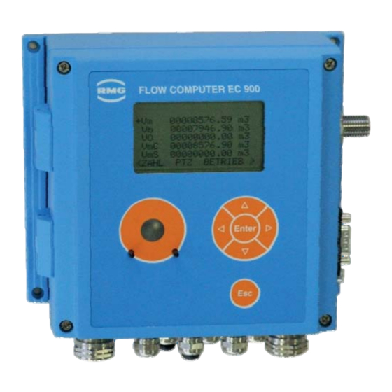
The electronic system and pressure transmitter of the EC 900 are fitted into an aluminium casing. On the front, there is a 128 x 64 dot matrix display where alphanumeric characters can be dis- played in 6 lines with 20 characters each. -
Page 13: Electronic Components
CONSTRUCTION AND FUNCTION .......................................... Electronic components The EC 900 comprises two boards in each case: 1. The main unit is fixed to the casing cover. It performs the measurement, correction and display functions. The calibration switch is also located on this board. - Page 14 CONSTRUCTION AND FUNCTION .......................................... Type EC 912 (Emergency) Battery Pressure transmitter The EC 912 version has been approved for Ex zone 1 as an intrinsically safe device. The boards of the EC 911 and EC 912 are identical to each other; they differ in that the battery of the externally supplied EC 912 serves only as an emergency battery.
- Page 15 CONSTRUCTION AND FUNCTION .......................................... Type EC 921 < No longer available > Modem Pressure transmitter The EC 921 version is intended for use in Ex zone 2; it is not permissible to operate this device in Ex zone 1. It is powered by two lithi- um batteries as standard: one for the correc- tor and the other for the internal communica- tion module.
- Page 16 CONSTRUCTION AND FUNCTION .......................................... Type EC 922 Modem Pressure transmitter The EC 922 version is intended for use in Ex zone 2; it is not permissible to operate this device in Ex zone 1. It is externally powered and includes a power pack (24 VDC or 115/230 VAC).
-
Page 17: Calculation Of The Volume At Base Conditions
GERG 88S, AGA-NX-19, AGA-NX-19 corr. and AGA Gross 1 for natural gas. Totalizers Overview The EC 900 has three types of volume totalizers: Totalizer for the original volume at measurement conditions V Totalizers for the volume at measurement conditions V... -
Page 18: Disturbance Totalizers
Time system General The EC 900 has been equipped with a time system which fulfils not only PTB requirements but also international requirements. This includes in particular a programmable change to summer or standard time. Rules for changing time The rules for changing the date and time are stipulated in PTB Requirement PTB-A 50.7. -
Page 19: Data Protection
.......................................... Data protection The program of the EC 900 is protected by a checksum. The checksum of the program version can be read under "CS displd" in the "TYPE" book. On the same screen, the user can initiate a manual check of the checksum via "Calc CS"... -
Page 20: Data Logger
CONSTRUCTION AND FUNCTION .......................................... Data logger Maximum values (maximum load) In order to enable the gas volume corrector to be approved as a maximum-load recording device, it is necessary to calculate and store the maximum values of a measuring period (hourly values) and the maximum daily values for the V and V channels. -
Page 21: Archives And Logbooks
CONSTRUCTION AND FUNCTION .......................................... Archives and logbooks Archive structure The DSfG terminology differentiates between archives and logbooks. In order to be able to transfer data in compliance with the DSfG-B protocol, the archives and logbooks must have a particular structure. Archive Name Function... -
Page 22: Disturbance Archive
CONSTRUCTION AND FUNCTION .......................................... Disturbance archive In addition to the periodic archive, there is an independent disturbance archive. Contrary to the periodic archive, the disturbance archive is filled only if the corrector is under fault conditions. The following data is stored: Archive index Time stamp Running number... -
Page 23: Monthly Archive
CONSTRUCTION AND FUNCTION .......................................... Monthly archive In the monthly archive, the following values are stored at the end of a month: Archive index Time stamp Running number Totalizer readings for V and V The relevant statuses of the above totalizers Disturbance totalizer readings for V and V The relevant statuses of the above totalizers... -
Page 24: Parameter Change Logbook
CONSTRUCTION AND FUNCTION .......................................... Information (clear text, only transmitted via Modbus) Source of change (e.g. keyboard, COM1, optical interface) Checksum for the data record (CRC) * The device itself will display the address of the Modbus register. When calling data via DSfG-B, the data element identifier will be transferred with the relevant parameter. -
Page 25: Event Archive
CONSTRUCTION AND FUNCTION .......................................... Event archive The event archive records all events. As regards its contents, it is a combination of the parameter logbook, event logbook and load archive. Here not only disturbance events but also other events (e.g. opening the calibration code or changing a parameter) are recorded. The following data is stored for each event: Archive index Time stamp... -
Page 26: Communication
MDA). The interface is available in identical form on the corrector and the communication unit. If the data is called via a PC, the PC program must be able to enable the RTS or DTR control line in order to establish communication with the EC 900 via the read head. Electrical interface Alternatively, an RS 232, RS 422 or RS 485 interface is available as interface for remote data transmission. -
Page 27: Transmission Protocols
CONSTRUCTION AND FUNCTION .......................................... Transmission protocols M900 protocol The M900 protocol (MRG 910/EC 694 protocol) has been implemented (enhanced functionality) so that the Dialog 900 service program can be used. DSfG-B protocol The DSfG-B protocol is implemented in the CU as standard. The device has been prepared to im- plement SELMA in conjunction with DSfG-B. -
Page 28: Safety Instructions
.......................................... Safety instructions The EC 900 PTZ corrector is used to calculate the volume at base conditions of gases from the vol- ume at measurement conditions, pressure and temperature as well as to transfer measured or cal- culated values via digital interfaces and pulse or analogue outputs. -
Page 29: Instructions For The Installer
Applicable in Ex zone 1 or 2 Applicable in Ex zone 2 The EC 911, EC 912, EC 921 and EC 922 devices from the EC 900 series are apparatus for areas subject to explosion hazards. The volume corrector is used in measuring and control engineering for measuring pressure, temperature and volume pulses. -
Page 30: Commissioning
RMG Messtechnik. Changing the battery When changing the battery, only the specially manufactured main batteries from RMG Messtechnik may be used. These must not be changed when the equipment is in operation. The same conditions apply for the B1 back-up battery (button cell) which powers the clock. -
Page 31: Special Condition For Ec 921 / Ec 922
SAFETY INSTRUCTIONS .......................................... Special condition for EC 921 / EC 922 The D-Sub connector mounted laterally to the case must not be plugged or pulled under voltage. If it remains unused, it has to be covered with a protective cap. All signal circuits must be kept potential free. - Page 32 SAFETY INSTRUCTIONS .......................................... Electrical data Note: The following data is only valid for the operation of the EC900 in Ex zone 2. The values valid for operation in Ex zone 1 can be found in the approval from page 133 to page 136. Power supply ..........
- Page 33 SAFETY INSTRUCTIONS .......................................... Signal input Reed/Namur ..........Energy limited Terminal X5 Maximum values per circuit E3+, E3- = 10.6 V Terminal X6 = 12.5 mA E4+, E4- Characteristic line: linear Terminal X7 and L are negligible E5+, E5- Terminal X8 E6+, E6- Terminal X9 E7+, E7-...
-
Page 34: Installation
6L) on the right of the device. A three-way check valve can be installed between the gas meter and the EC 900 to check the pressure transmitter (e.g. in the event of follow-up verifications). During installation you must make sure that the piping from the pressure transmitter to the... -
Page 35: Electrical Connections
INSTALLATION .......................................... Electrical connections Devices for Ex zone 1 (EC 911 and EC 912) The versions for Ex zone 1 may only be connected to certified intrinsically safe circuits. Further equipment may only be connected if the relevant explosion protection condi- tions such as the permissible capacitance and inductance have been complied with (see the separate ATEX approval documentation). -
Page 36: Devices For Ex Zone 2 (Ec 921 And Ec 922)
INSTALLATION .......................................... Devices for Ex zone 2 (EC 921 and EC 922) The versions for Ex zone 2 may not be operated in Ex zone 1. In Ex zone 2 it is not nec- essary to provide electrical isolation in order to connect other equipment. If the devices are powered externally, make sure that the power supply is correct. -
Page 37: Pin Assignments - Modem/Ethernet
INSTALLATION .......................................... Pin assignments - modem/Ethernet The EC 921 and EC 922 versions have a modem connection on the connection board (see previous page). In this way, (depending on whether the device is equipped with an analogue modem or a TCP/IP module), it can be connected to the telephone network or a computer network (Ethernet). -
Page 38: Connection Of An External Cu 900 Communication Module
INSTALLATION .......................................... Connection of an external CU 900 communication module Use connectors with a degree of protection of IP65 or higher to connect the communication mod- ule to the interface of the EC 912. Recommendation: D-Sub connector element of type CD-DB9FEZBR with protective hood of type FWAF1GAE, both from FCT/BTX Technologies (with screw terminals to avoid soldering in the hazardous area). -
Page 39: Requirements For The Protection Class Ip65
INSTALLATION .......................................... Requirements for the protection class IP65 To guarantee the IP65 protection class, the permissible outer diameter of the connecting cables has to be ensured, in addition to the use of appropriate sub-D connectors (see previous page): Cable glands of type M12: clamping range 3 to 6.5 mm, type M16: clamping range 5 to 10 mm. The clamping range for the Sub-D connector (type: FWAF1GAE) is 6-8 mm. -
Page 40: Commissioning
Commissioning Configuring the interface The electrical interface of the EC 900 can be configured as an RS 232, RS 422 or RS 485 interface using jumpers. In the case of the RS 485 interface, termination is recommended. EC 911 and EC 912... -
Page 41: Ec 921 And Ec 922
COMMISSIONING .......................................... EC 921 and EC 922 EC 921 EC 922 Jumper row vertical Jumper row horizontal Note: The wiring compartment has been reworked in the meantime. You can see the current version on page 28. Interface mode RS 232 RS 422 RS 485 RS 485... -
Page 42: Defining Codes
Changing parameters" for a description of how to enter them. Code "M" has been permanently specified and cannot be changed or made visible. It enables the factory settings to be changed by RMG's service engineers. Setting the contrast The contrast of the LCD display is set in the factory in such a way that the texts can be read easily when you look vertically at the device. -
Page 43: Operation
How to operate the EC 900 The EC 900 can be operated by using the keys of the device or via the Dialog 900 read-out and pa- rameterization program. While you can display and change only the most important parameters by using the keys of the device, you can view all parameters which can be read or changed if you use the Dialog 900 program. - Page 44 OPERATION .......................................... there are two lines which are named "pmin" and "pmax". The lines represent the final level in our structure. They may be lines that serve only to display data or there are lines for entering data. With the "Escape" button you scroll back one level in the structure. Being in the "chapters" level and pressing the "Esc"...
-
Page 45: Keys
OPERATION .......................................... Keys The six control buttons located on the front of the device have the following functions: In the menu In input mode To switch over between the individual To jump to the previous or following books. position of the number to be changed. To move between the menu items of To increase or reduce the digit of the lines 1 to 5. -
Page 46: Accessing Device Data
Using the Dialog 900 operating software, you can see these parameters even without entering the code. Codes Accessing the data of the EC 900 is made possible via eight different codes. They stand for differ- ent authorization levels. Designation... -
Page 47: Calibration Switch
OPERATION .......................................... Calibration switch In order to make several changes (for example, to delete the legal metrological logbook), you have not only to enter the M code, but also open the calibration switch. It is located at the bottom of the main unit on the casing cover (below a plastic strip) and is protected by a seal for custody transfer metering. -
Page 48: Preconditions For Important Operations
OPERATION .......................................... Preconditions for important operations Setting totalizers Book: TOT, menu: Totalizer/Setting totalizers/ Set VmL: U code Set Vb: C code and calibration switch Set Vm: C code Set VO: C code Resetting totalizers Book: TOT, menu: Totalizer/Totalizer mode/ Reset: C code for {Dist. -
Page 49: Changing Parameters
Examples of programming The following examples describe frequent or less frequent but important programming work on the EC 900. In these examples (with the exception of the first one), it is assumed that the code has already been entered. The examples start with the customized display screen. Usually, the cursor is located somewhere in the menu. -
Page 50: Inputting A Code
Codes C1, C2 and C3 have the same priority. This also applies for codes U1 and U2. Enablement of the relevant code can also be performed via the interfaces. The manufacturer's code (code M) is to be used only by RMG's service engineers. All entries of codes are recorded in the appropriate archives. -
Page 51: Displaying And Changing Parameters For Calculating The K Coefficient
OPERATION .......................................... Displaying and changing parameters for calculating the K coefficient In the following example of programming, the superior calorific value is to be changed from 9.23 to 10.41 in order to calculate the K coefficient in compliance with GERG-88S, and the standard densi- ty and CO content are to be displayed. - Page 52 OPERATION .......................................... 7. Press Enter again. Now the window will open where you can change the superior calorific value. You can change the numerical value under the "New value" text. The cursor will be on the first position. Below that, there is the permissible range for the su- perior calorific value;...
-
Page 53: Displaying And Changing Pressure Parameters
OPERATION .......................................... Displaying and changing pressure parameters 1. You are on the customized display screen. Press " " twice to access the "PTZ" book. 2. In order to proceed, it is necessary to have the cali- bration code entered (code C1, C2 or C3)! 3. - Page 54 OPERATION .......................................... 6. The first line of the input mask shows the old value. In the third line, you can change the old value using the " " or " " cursor key for the digit and " " or " " for the input position.
- Page 55 OPERATION .......................................... 10. On the Modes of operation screen, you can set the unit and operating mode of the pressure transmitter. Press " " and Enter to access the following input mask: 11. In this mask, press " " or " " to browse through fixed texts for selection.
-
Page 56: Adjusting Interface Parameters
OPERATION .......................................... Adjusting interface parameters 1. Make your optical interface settings in the "Com opt" chapter of the "COMM" book. 2. The data shown in the illustration on the left corre- spond to the basic settings for operating the optical interface via Modbus. -
Page 57: Changing The Pulse Value Of The Gas Meter
OPERATION .......................................... Changing the pulse value of the gas meter 1. On the customized display screen press " " to ac- cess the "TYPE" book; then press " " twice to access the Volume meter chapter. Press Enter to access the Volume meter screen. -
Page 58: Setting Or Resetting Totalizers
OPERATION .......................................... Setting or resetting totalizers 1. In the "Totalizers" ("TOT") book, press Enter in any line to reach the next chapter. 2. Press " " to reach the "Setting totalizers" line, and then press Enter to move to the next screen. 3. -
Page 59: Device Data
The checksum can be recalculated anytime if the "Calc CS" parameter is set to "Yes". 3. Press " " more than once to reach the lower lines. The checksum of the EC 900 is calculated according to CRC-CCITT (CRC16)........................................... -
Page 60: Deleting An Event
OPERATION .......................................... Deleting an event 1. The first line of a screen (info line) indicates if an event has occurred. The message(s) it- self/themselves can be seen in the overview of the "Operating data" ("OPER.") book. Here all events are outputted by number in line 2. -
Page 61: On-The-Fly Calibration
OPERATION .......................................... On-the-fly calibration 1. Press " " to jump to the totalizer display and select any totalizer. 2. The visible window will open even if another totalizer is selected. Now select "On-the-fly calibr.". 3. Press Enter to start on-the-fly calibration. Now the TVm and TVb totalizers will start to run together with a stopwatch (Test time). -
Page 62: Viewing Archive Entries (Example: Periodic Archive)
OPERATION .......................................... Viewing archive entries (example: periodic archive) 1. Use " " or " " to jump to the "TARIFF" book and se- lect "Archives". Viewing the periodic archive, which is described below, functions in the same way for all the other archives and the logbooks. - Page 63 OPERATION .......................................... 4. Press " " to reach further lines below TS: "Cur level" shows the index of the last archive entry. Since the archives are circular archives with the ex- ception of the legal metrological logbook, the index will again start at 1 after an archive overflow. "Opt read"...
-
Page 64: Viewing Maximum Load Values
Viewing maximum load values Description The EC 900 includes a maximum-load display feature which records and stores the maximum quan- tity supplied during a supply period and the maximum quantity supplied during a day (gas day). The supply period can be set to a value between 1 and 600 minutes. In the factory, the supply peri- od has been preset at 60 minutes. -
Page 65: Maximum Load Display
OPERATION .......................................... Maximum load display If you select "Current load" in the customized display and press Enter, you will reach another selection screen. Here you can select to display the current supply quanti- ty of the current supply period within the current gas day, the current supply quantity of the current supply period within the current month and the current supply quantity of the current gas day within the current month. -
Page 66: Monitoring The Supply Period
OPERATION .......................................... Monitoring the supply period Under "Totalizer functions" (page 62) you can reach two input fields under "Load limits" where the maximum value of the current supply period or the maximum value of the gas day can be entered. If these limits are exceeded, an entry will be made in the event archive (see page 17). -
Page 67: List Of Parameters And Operating Modes
OPERATION .......................................... List of parameters and operating modes The following tables show the setting options for the operating modes in parentheses and separat- ed with vertical lines, e.g. {Off|0-4.5V|4-20mA|Default}. If the relevant fields are addressed by an external program, appropriate numerical values (position) are to be assigned to the texts. -
Page 68: Screen: Extended Customized Display
OPERATION .......................................... Screen: Extended customized display +System values Manufacturer's code (M code) required to continue +Pressure measurem. Manufacturer's code (M code) required to continue +Temperature meas. Manufacturer's code (M code) required to continue +Analogue input 1 Manufacturer's code (M code) required to continue +Analogue input 2 Manufacturer's code (M code) required to continue +Case temperature... -
Page 69: Screen: 1.0.2.0 (Use Of The Digital Inputs)
OPERATION .......................................... Screen: 1.0.2.0 (Use of the digital inputs) Mod M Volume input VM {Off|Totalizer} Mod R Volume input VR {Off|Totalizer} Mod 3 Digital input 3 {Off|Totalizer|Tamper c. C|Tamper c. O| Time sync|Fault res.} Mod 4 Digital input 4 {Off|Totalizer|Tamper c. C|Tamper c. O| Time sync|Fault res.} Mod 5 Digital input 5 {Off|Limit contact}... -
Page 70: Screen: Tot
OPERATION .......................................... Screen: TOT 00123400.00 m3 Press Enter to go to screen 1.1.0.0 00005566.00 m3 Press Enter to go to screen 1.1.0.0 00009870.00 m3 Press Enter to go to screen 1.1.0.0 +VbD 00000000.00 m3 Press Enter to go to screen 1.1.0.0 +VmD 00000000.00 m3 Press Enter to go to screen 1.1.0.0 +VmL... -
Page 71: Screen: 1.1.3.0 (Totalizer Mode)
OPERATION .......................................... Screen: 1.1.3.0 (totalizer mode) Stop Alarm stop Totalizer mode {Alarm stop|Alarm run} Reset Clearing totalizers {Off|Dispatcher|Dist. total.|Totalizers| Main totaliz.} Vm unit Unit for the volume at measurement conditions {m3|ft3|yd3|gal} Vb unit Unit for the volume at base conditions {m3|ft3|yd3|gal} Vm per National Vm mode {MID|National}... -
Page 72: Screen: Ptz
OPERATION .......................................... Screen: PTZ 1.008 bara Press Enter to go to screen 2.1.0.0 27.30 °C Press Enter to go to screen 2.2.0.0 >C 0.903516 Conversion factor 1.00068 Press Enter to go to screen 2.3.0.0 >SC 0.99932 Supercompressibility +AGA 8 Components Press Enter to go to screen 2.4.0.0 <PTZ OPER. -
Page 73: Screen: 2.1.4.0 (Pressure Parameters)
OPERATION .......................................... Screen: 2.1.4.0 (pressure parameters) poffs 0.00000 Correction value for the pressure at measurement conditions Upmin 0.50000 V Voltage Umin (V) Upmax 4.50000 V Voltage Umax (V) %Upmin 0.00000 Per cent Umin %Upmax 100.000 Per cent Umax <PTZ OPER. TARIFF> "PTZ"... -
Page 74: Screen: 2.2.2.0 (Temperature Limits)
OPERATION .......................................... Screen: 2.2.2.0 (temperature limits) tmin -20.00 °C Lower alarm limit for temperature tmax 60.00 °C Upper alarm limit for temperature <PTZ OPER. TARIFF> "PTZ" book Screen: 2.2.3.0 (temperature default) tdef 10.00 °C Replacement value for temperature <PTZ OPER. TARIFF> "PTZ"... -
Page 75: Screen: 2.3.1.0 (Values Displayed For The Compressibility Factor)
OPERATION .......................................... Screen: 2.3.1.0 (values displayed for the compressibility factor) >Zm 0.99833 Compressibility factor (measurement conditions) >Zb 0.99771 Compressibility factor (base conditions) >dm calc 0.726 kg/m3 Calculated density from GERG (kg/m3) >db calc 0.8000 kg/m3 Calculated standard density for GERG >rd calc 0.6187 Calculated relative density for GERG... -
Page 76: Screen: 2.4.0.0 (Components For K Coefficient Calculation Using Aga 8-92Dc)
OPERATION .......................................... Screen: 2.4.0.0 (components for K coefficient calculation using AGA 8-92DC) Oper.Mode: DSfG_Modbus Source of gas components {Off|DSfG_Modbus|Set value} +CO2: 0.5000 Mol% Value for calculation, press Enter to go to screen 2.4.1.0 +H2: 0.0000 Mol% Value for calculation, press Enter to go to screen 2.4.2.0 +N2: 6.0000 Mol% Value for calculation, press Enter to go to screen 2.4.3.0... -
Page 77: Screen: Oper
OPERATION .......................................... Screen: OPER. > No messages Fault message(s) Time 11:10:05 Display and setting of time and date +Date 27.08.13 Press Enter to go to screen 3.2.0.0 CodeC1 ******** Calibration code 1 (for changing parameters under legal control) CodeC2 ******** Calibration code 2 (for changing parameters under legal control) CodeC3 ******** Calibration code 3 (for changing parameters under legal control) -
Page 78: Screen: 3.2.2.0 (Time Parameters)
OPERATION .......................................... Screen: 3.2.2.0 (time parameters) Cc03:00:00 27.10.13 Switching over to summer time Nc02:00:00 30.03.14 Switching over to standard time Zone Displaying standard time (0) or summer time (1) TZ00:00:00 01.11.07 Time of the last time change (standard/summer time) RTCcor 2.000000 Correction factor, clock Tswitch D.s.t off... -
Page 79: Screen: 3.5.0.0 (Customized Display)
OPERATION .......................................... Screen: 3.5.0.0 (customized display) C disp3 1022 Modbus address to show customized line 3 C disp4 4910 Modbus address to show customized line 4 C disp5 4912 Modbus address to show customized line 5 C disp6 1412 Modbus address to show customized line 6 C disp7 1410 Modbus address to show customized line 7 C disp8 1420... -
Page 80: Screen: 3.8.0.0 (Power Supply)
OPERATION .......................................... Screen: 3.8.0.0 (power supply) Setup power supply Sel. of standby power supply {Battery|24V|110/230V|8.2V} <OPER. TARIFF FLOW > "OPER." book NOTE! After the power supply has been changed, the device will be rebooted automatically, since this requires a new system initialization. The parameters of the device will remain unaffected there- by and will be retained. -
Page 81: Screen: Tariff
OPERATION .......................................... Screen: TARIFF + Archives Press Enter to go to screen 4.1.0.0 +Logbooks Press Enter to go to screen 4.2.0.0 +Archive parameters Press Enter to go to screen 4.3.0.0 +Archive modes Press Enter to go to screen 4.4.0.0 +Logbook modes Press Enter to go to screen 4.5.0.0 +Maximum load test Press Enter to go to screen 4.6.0.0... -
Page 82: Screen: 4.1.1.1 (Periodic Archive - Entries)
OPERATION .......................................... optical interface of the corrector. "Com1 read" indicates how many entries have been read via the COM1 port of the EC 911 or EC 912 with ISS 900. If it is an EC 912 with external CU or an EC 922, then here is displayed, how many entries have been read via the internal connection between ECxx and CU. -
Page 83: Screen: 4.1.2.0 (Daily Archive)
OPERATION .......................................... Status bit string: Bit0: Alarm collective message Bit1: Error measured value volume at measurement conditions Bit2: Error measured value pressure or density at measurement conditions Bit3: Error measured value temperature or density at base conditions Bit4: Minimum warning limit value Vb, P, T, rb or rn Bit5: Min. - Page 84 OPERATION .......................................... Daily archive Headline: Daily archive 06:00:00 06.11.13 Time stamp: Time and date Vm status: Totalizer status: (0: running, 1: stopped) 00000000 m3 Totalizer reading disturbance quantity volume at base cond. VbD status: Totalizer status: (0: running, 1: stopped) 00000000 m3 Totalizer reading disturbance quantity volume at meas.
-
Page 85: Screen: 4.1.3.0 (Monthly Archive)
OPERATION .......................................... Screen: 4.1.3.0 (monthly archive) +Monthly archive Press Enter to go to screen 4.1.3.1 Read rec. Input of the read record No. xxxx (Modbus Omni) Level Display of the level (max. 24 entries). Reset only by deleting the archive. >Run.No Last running number >TS07:00:00 27.08.13... - Page 86 OPERATION .......................................... Monthly archive Headline: Monthly archive 06:00:00 01.11.13 Time stamp: Time and date K status: Meas. val. status (0: ok, 2: def. value, 3: fixed value, 4: holding value) 0.905765 Mean value of conversion factor C status: Meas. val. status (0: ok, 2: def. value, 3: fixed value, 4: holding value) Condition: Status overview volume corrector 10000000000000...
-
Page 87: Screen: 4.1.4.0 (Disturbance Archive)
OPERATION .......................................... Screen: 4.1.4.0 (disturbance archive) +Disturbance archive Press Enter to go to screen 4.1.4.1 Read rec. Input of the read record No. xxxx (Modbus Omni) Level Display of the level (max. 600 entries). Reset only by deleting the archive. >Run.No Last running number >TS12:00:15 01.07.13... -
Page 88: Screen: 4.1.5.1 (Event Archive - Entries)
OPERATION .......................................... Screen: 4.1.5.1 (event archive - entries) Event archive Headline: Event archive Index/CRC: 478/5981 Memory position of the entry / checksum of the entry Time stamp: Time stamp of the entry 07:57:13 07.11.13 Time and date Running No.: Running number of the displayed entry All faults reset Name of the event Last index no.:... -
Page 89: Screen: 4.1.6.1 (Load Archive - Entries)
OPERATION .......................................... Screen: 4.1.6.1 (load archive - entries) Load archive Headline: Load archive Index/CRC: 549/CF0B Memory position of the entry / checksum of the entry Time stamp: Time stamp of the entry 13:00:00 07.11.13 Time and date Running No.: 2346 Running number of the displayed entry Last index no.: Memory position of the last entry... -
Page 90: Screen: 4.2.0.0 (Logbooks)
OPERATION .......................................... Screen: 4.2.0.0 (logbooks) +Legal metr. logbook Press Enter to go to screen 4.2.1.0 +Parameter logbook Press Enter to go to screen 4.2.2.0 +Event logbuch Press Enter to go to screen 4.2.3.0 < TARIFF FLOW TYPE > "TARIFF" book Screen: 4.2.1.0 (legal metrological logbook) +Legal metr. -
Page 91: Screen: 4.2.2.0 (Parameter Logbook)
OPERATION .......................................... Screen: 4.2.2.0 (parameter logbook) +Logbook parameters Press Enter to go to screen 4.2.2.1 Read rec. Input of the read record No. xxxx (Modbus Omni) Level Display of the level (max. 600 entries). Reset only by deleting the archive. >Run.No Last running number >TS07:34:46 27.08.13... -
Page 92: Screen: 4.2.3.0 (Event Logbook)
OPERATION .......................................... Screen: 4.2.3.0 (event logbook) +Event logbook Press Enter to go to screen 4.2.3.1 Read rec. Input of the read record No. xxxx (Modbus Omni) Level Display of the level (max. 600 entries). Reset only by deleting the archive. >Run.No Last running number >TS08:48:28 27.08.13... -
Page 93: Screen: 4.4.0.0 (Archive Modes)
OPERATION .......................................... Screen: 4.4.0.0 (archive modes) Archives Archive displays {Off|On|Test} Profile DSfG Archive configuration for Modbus export {Standard|DSFG} Period Without event Configuration of the periodic archive {Without event|With event} Arc res. Reset of archives {Off|Period|Days|Months|Disturb|Event|Load|All arch.} Add evt. Additional recording in the event archive {Off|OPWork| RSWork|SetClk|Last|Month|Day|Period|RTCInt} Arch max Level limitation for all archives... - Page 94 OPERATION .......................................... The test is disabled 10 minutes on the hour until 2 minutes after the hour and may only be per- formed if the flow rate is zero. In order to start the test, you have to set "Archives" mode at "Test" in screen 4.4.0.0. This will cause the totalizer readings and the first 10 entries of the periodic archive to be saved and the con- tents to be set at zero.
-
Page 95: Screen: Flow
OPERATION .......................................... Screen: FLOW 0.000 m3/h Press Enter to go to screen 5.1.0.0 0.000 m3/h Press Enter to go to screen 5.1.0.0 <FLOW TYPE COMM > "FLOW" book Screen: 5.1.0.0 (flow rate) +Measured values Press Enter to go to screen 5.1.1.0 +Limits Press Enter to go to screen 5.1.2.0 +Parameters... -
Page 96: Screen: 5.1.3.0 (Flow Rate Parameters)
A two-channel volume metering is not possible in this configuration of the EC900. In the EC 911 or a different version of the EC 900, in which the supply of the device is set to battery, the flow rate measurement is blocked. - Page 97 In addition to the setting options mentioned above, it is possible to apply a signal "valve closed" to the digital input 6. Then in the EC 900 a warning message is generated, if the flow rate measure- ment is activated with creeping quantity suppression as soon as the flow rate exceeds the creeping quantity limit and the signal "valve closed"...
-
Page 98: Screen: Type
Press Enter to go to screen 6.4.0.0 +Checksum Press Enter to go to screen 6.5.0.0 +Customer data Press Enter to go to screen 6.6.0.0 +RMG data Press Enter to go to screen 6.7.0.0 <TYPE COMM OUTPUTS> "TYPE" book Screen: 6.1.0.0 (type of pressure transmitter) -
Page 99: Screen: 6.3.0.0 (Type Of The Volume Meter)
{5 sec|10 sec|15 sec|30 sec} <TYPE COMM OUTPUTS> "TYPE" book NOTE! With battery-powered devices, VO cycle has to be at "30 sec". Screen: 6.4.0.0 (device data) 2013 Year of construction of the EC 900 >ID 00000000000001 Device identification >Ver-EC900-V11.30 DE Software version... -
Page 100: Screen: 6.5.0.0 (Checksum)
OPERATION .......................................... Screen: 6.5.0.0 (checksum) >CS calib CB55 Checksum of the parameters protected by the calibration code >CS user E596 Checksum of the parameters protected by the user code >CS manuf 4796 Checksum of the parameters protected by code M <TYPE COMM OUTPUTS>... -
Page 101: Screen: 6.7.0.0 (Rmg Data)
OPERATION .......................................... Screen: 6.7.0.0 (RMG data) Order-No 3556 RMG order number under which the device is managed. Pi SIEMENS|TC63|RE Device type of the plugged-in expansion module Pi-s 900260109 Serial number of the expansion module R-MU 1101-06034b Manufacturer number of the corrector board... -
Page 102: Screen: 7.1.0.0 (Optical Interface)
OPERATION .......................................... Screen: 7.1.0.0 (optical interface) Op type Slave Selection of the type of optical interface MU {Off|Slave} Op baud 9600 Selection of the baud rate of the opt. interface MU {1200|2400|4800|9600} Op bits Selection of the data bits for the optical interface (fixed 8 bit) Op parity Even Sel. -
Page 103: Screen: 7.3.0.0 (Com Filters)
OPERATION .......................................... IMPORTANT: The factory settings of this interface must not be changed for the device types EC 912 and EC 922! Screen: 7.3.0.0 (Com filters) F reg1 Transfer filter 1 F reg2 Transfer filter 2 F reg3 Transfer filter 3 F reg4 Transfer filter 4 F reg5... - Page 104 OPERATION .......................................... Explanation of the status displays After a reboot of the CU first the archives of the corrector are read. Here in the first 4 digits from the left, the archive number is displayed (e.g. 98200000, 98400000). Then all necessary parameters are read. This is done using a matrix, where the column stands in the first digit, the next three digits are reserved for the rows and the last 4 digits indicate the Modbus address of the parameter specified.
-
Page 105: Screen: 7.5.0.0 (Com Test)
General: The specified indicators are also available via Modbus or via the Dialog 900 program. Be- cause the query speed may be lower than the update the display speed of the EC 900, reading the display on the EC 900 is preferable. -
Page 106: Screen: Outputs
OPERATION .......................................... Screen: OUTPUTS +Digital outputs Press Enter to go to screen 8.1.0.0 +Analogue outputs Press Enter to go to screen 8.2.0.0 < OUTPUTS CU > "OUTPUTS" book Screen: 8.1.0.0 (digital outputs) +Digital output 1 Press Enter to go to screen 8.1.1.0 +Digital output 2 Press Enter to go to screen 8.1.2.0 +Digital output 3... -
Page 107: Screen: 8.1.1.2 (Digital Output 1 – Parameters)
DA1 src is digitally transmitted to the CU 900 from where it is outputted via pulse output 1. NOTE: It is possible that delays occur. As a result, pulse output 1 of the CU 900 can no longer be used as digital output 3 of the EC 900. Screen: 8.1.2.0 (digital output 2) +Display values Press Enter to go to screen 8.1.2.1... -
Page 108: Screen: 8.1.2.1 (Digital Output 2 – Display Values)
DA2 src is digitally transmitted to the CU 900 from where it is outputted via pulse output 2. NOTE: It is possible that delays occur. As a result, pulse output 2 of the CU 900 can no longer be used as digital output 4 of the EC 900. Screen: 8.1.3.0 (digital output 3) +Display values Press Enter to go to screen 8.1.3.1... -
Page 109: Screen: 8.1.3.2 (Digital Output 3 – Parameters)
OPERATION .......................................... Screen: 8.1.3.2 (digital output 3 – parameters) DA3 src Pressure Selection of the source for digital output 3 {Pressure|Temperat.|Conv. fact.|K coeff.| Flow|Flow bcond|Input 3|Input 4|Input 5} DA3 type Mi/Ma. co. Selection of the type of digital output 3 {Off|Per. pulse|Alarm co.|Warn co.|C sw. -
Page 110: Screen: 8.1.6.0 (Digital Output 6)
OPERATION .......................................... Screen: 8.1.5.0 (digital output 5) +Display values Press Enter to go to screen 8.1.5.1 +Parameters Press Enter to go to screen 8.1.5.2 <OUTPUTS CU > "OUTPUTS" book Screen: 8.1.5.1 (digital output 5 – display values) >DA5 set Status of the output contact <OUTPUTS CU >... -
Page 111: Screen: 8.1.6.2 (Digital Output 6 - Parameters)
OPERATION .......................................... Screen: 8.1.6.2 (digital output 6 – parameters) DA6 src K coeff. Selection of the source for digital output 6 {Pres- sure|Temperat.|Conv. fact.|K coeff.| Flow|Flow bcond|Input 6|Input 7|Input 8} DA6 type Mi/Ma. co. Selection of the type of digital output 6 {Off|Day max.|Alarm co.|Warn co.|C sw. -
Page 112: Screen: 8.2.1.2 (Analogue Output 1 - Parameters)
OPERATION .......................................... Screen: 8.2.1.2 (analogue output 1 - parameters) A1 type 4-20mA Selection of the type of analogue output 1 {Off|0-20mA|4-20mA|Cal.cur.on} A1 src Sel. of the source for analogue output 1 {Pres- sure|Temperat.|Conv. fact.|K coeff.|Qm|Qb| Freq. chan1|Freq. chan2} A1 min 0.000 Analogue output 1, minimum range value A1 max... -
Page 113: Screen: 8.2.3.0 (Analogue Output 3)
OPERATION .......................................... Screen: 8.2.3.0 (analogue output 3) +Display values Press Enter to go to screen 8.2.3.1 +Parameters Press Enter to go to screen 8.2.3.2 <OUTPUTS CU > "OUTPUTS" book Screen: 8.2.3.1 (analogue output 3 - display values) >A3 phys 1.018 Analogue output 3, physical value >A3 mA 7.908 mA... -
Page 114: Screen: 8.2.4.2 (Analogue Output 4 - Parameters)
OPERATION .......................................... Screen: 8.2.4.2 (analogue output 4 - parameters) A4 type 4-20mA Selection of the type of analogue output 4 {Off|0-20mA|4-20mA|Cal.cur.on} A4 src Temperat. Sel. of the source for analogue output 4 {Pressure|Temperat.|Conv. fact.|K coeff.|Qm|Qb| Freq. chan1|Freq. chan2} A4 min -20.000 Analogue output 4, minimum range value A4 max... -
Page 115: Screen: 9.1.1.1 (Parameters For Radio Module Gsm)
"CU" book Screen: 9.1.1.2 (parameters for GPRS modem) Mode: GSM (CSD) GSM/GPRS {0·GSM (CSD)|1·GPRS-M900} Provider: Radio network operator {0·D1|1·D2|2·E+|3·O2} rmg-ebe0.dynds. Domain name of the switchboard APN: Access point name – access GPRS Password: Password – access GPRS User: User name – access GPRS... -
Page 116: Screen: 9.1.1.3 (Parameters Modem Interface, Protocols)
Date and time Modemreset Execute modem reset Call Server Prepare call switchboard <CU MODEM SERVICES > "CU" book Screen: 9.1.2.0 (USB: internal in EC 900 / external in CU 900) Baudrate: 9600 Transmission speed {0·300|1·600|2·1200| 3·2400|4·4800|5·9600|6·19200|7·38400|8·57600| 9·115200} Databits: Number data bits radio network operator {7|8}... -
Page 117: Screen: 9.1.3.0 (Serial: Db9 On The Right Side Of Ec 900 Case)
OPERATION .......................................... Screen: 9.1.3.0 (serial: DB9 on the right side of EC 900 case) Baudrate: 9600 Transmission speed {0·300|1·600|2·1200| 3·2400|4·4800|5·9600|6·19200|7·38400|8·57600| 9·115200} Databits: Number data bits radio network operator {7|8} Parity: Parity None (N), Odd (O), Even (E) {N|O|E} Stopbits: Number stop bits {1|2}... -
Page 118: Screen: 9.2.0.0 (Time Parameters)
OPERATION .......................................... Screen: 9.2.0.0 (time parameters) Time: 12:00:23 Current time CU Date: 16.07.13 Current date CU >Time-zone Current time zone (M: normal time, S: daylight saving time) Last Time-set: Last setting of CU time: > 15.07.13 14:02:53 Date and time Calc.TZ-Shift: Calculated (next) time zone change: >... -
Page 119: Screen: 9.3.1.0 (Eadrs)
OPERATION .......................................... Screen: 9.3.1.0 (EADRs) EADR-DFUe 1: DSfG recipient address remote transfer entity 1 EADR-DFUe 2: DSfG recipient address remote transfer entity 2 EADR-DFUe 3: DSfG recipient address remote transfer entity 3 EADR-DFUe 4: DSfG recipient address remote transfer entity 4 EADR-Wieser: DSfG recipient address Wieser entity EADR-Corrector:... -
Page 120: Screen: 9.3.4.0 (Ada Identification)
OPERATION .......................................... Screen: 9.3.4.0 (ada identification) ada-ID: Ident Type of identification (information for identification according to OBIS) {0·Ident|1·Ident&Location|2·Country-Ident} Country: Country code User: 123456 Identification for operator Zip code: 85560 Zip code measuring location Branche: Medium: 1 gas, 2 water Identifier: Meas.point Name measuring point Location: IdN 7RMG09I... -
Page 121: Fault Messages
Fault messages Alarms DSfG No. Display of the EC 900 Explanation 10-1 MU restart Watchdog or short power failure of the EC 900 11-0 p failure Failure of the pressure transmitter 11-1 p min range Minimum pressure range value violated downwards... -
Page 122: Warnings
OPERATION .......................................... Warnings DSfG No. Display of the EC 900 Explanation 10-7 Time synchron. Time synchronization failed 4431 55-0 MB function OP Illegal function Modbus OP 4432 55-1 MB dat addr. OP Illegal data address Modbus OP 4434 55-3 MB slavedev. OP... -
Page 123: Maintenance
MAINTENANCE .......................................... Maintenance .......................................... -
Page 124: Changing The Battery
Use only batteries from RMG with connecting cables and connectors. If you use other batteries, explosion protection will not be guaranteed after you have changed the bat-... -
Page 125: Devices For Ex Zone 2 (Ec 921 And Ec 922)
MAINTENANCE .......................................... Devices for Ex zone 2 (EC 921 and EC 922) Note: In the case of the EC 921 and EC 922 device types, it is not permissible to open the device in Ex zone 2. Therefore, prior to changing the battery, check the atmosphere with a gas alarm device! Corrector Modem... -
Page 126: Notes On The Use Of Batteries
MAINTENANCE .......................................... Notes on the use of batteries Lithium batteries retain their voltage until they are almost completely discharged so that the volt- age cannot be monitored with an appropriate indicator until the next battery change is necessary. You can enter the months until the next battery change is necessary under "Time values / Batt change"... -
Page 127: Back-Up Battery
MAINTENANCE .......................................... Back-up battery The main unit has been fitted with a button cell which serves as a back-up battery. This battery is only required to keep the clock running if there is a power failure. The data will be retained even after this battery has been removed. -
Page 128: Technical Data
TECHNICAL DATA .......................................... Technical data Casing Wall-mounting device Protection class IP 65 (suitable for outdoor installation) Ambient temperature range -25°C to 55°C Protection class Ex zone 1 / zone 2 Power supply Lithium battery Battery life > 6 years Connection for external power supply (EC 922) with DC power pack: 10 - 36 VDC with AC power pack:... - Page 129 TECHNICAL DATA .......................................... Digital outputs Number Characteristics Digital transistor outputs potential-free Permanently assigned Pulse outputs Vm, Vb User-parameterizable Message output for alarms, warnings Optional HF output for Vm Current outputs Number 4 on the communication unit Option, daughter board Data interfaces Optical interface as per IEC1107 Local access to data elements and archives Protocols...
- Page 130 TECHNICAL DATA .......................................... Data logger Characteristics Memory Ferro RAM 512 All data can be displayed. All data can be read out via the data interfaces. Archives Main archive – Measuring period Contents Event-oriented storage DSfG archive structure Additionally, K coefficient, conversion factor (C) Memory depth >...
-
Page 131: Annex
ANNEX .......................................... Annex Seal diagrams .......................................... - Page 132 ANNEX ..................................................................................
- Page 133 ANNEX .......................................... Sealing plan of the electronics before revision 8 ..........................................
- Page 134 ANNEX .......................................... Sealing plan of the electronics revision 8 ..........................................
- Page 135 ANNEX ..................................................................................
- Page 136 ANNEX ..................................................................................
-
Page 137: Wiring Diagrams
ANNEX .......................................... Wiring diagrams .......................................... - Page 138 ANNEX ..................................................................................
-
Page 139: Older Version Of Ec 921 And Ec 922
ANNEX .......................................... Older version of EC 921 and EC 922 The pin assignment for devices manufactured before 2010 has to be taken from the following illus- tration. Modem or Ethernet con- nection Power pack Power supply Earthing screw Digital outputs Digital inputs 5 to 8 Ref. -
Page 140: Ec Type Examination Certificates
ANNEX .......................................... EC type examination certificates The EC type examination certificate TÜV 08 ATEX 554643 as per Directive 94/9/EC applies to the intrinsically safe device types EC 911 and EC 912. Type of protection: II 2 G Ex ia IIC T4. The EC type examination certificate TÜV 08 ATEX 554647 as per Directive 94/9/EC applies to the ISS 900 power supply isolator even if the latter is installed in the CU 900 communication module. - Page 141 Subject to technical modification For further information please visit our website: www.rmg.com or contact your local sales support office to learn more about the RMG products. RMG Messtechnik GmbH Otto-Hahn-Straße 5 35510 Butzbach, Deutschland Tel: +49 (0) 6033 897 – 0 Fax: +49 (0) 6033 897 –...
Need help?
Do you have a question about the EC 900 and is the answer not in the manual?
Questions and answers