
Subscribe to Our Youtube Channel
Related Manuals for RMG ERZ 2000


Summary of Contents for RMG ERZ 2000
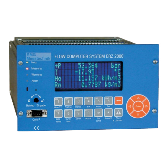
- Page 1 ERZ 2000 Short Operating Instructions RMG Messtechnik GmbH Status: Dec. 19, 2006 V 1.3...
-
Page 3: Table Of Contents
CONTENTS OVERVIEW OF FUNCTIONS ....................5 EXPLANATION OF THE MOST IMPORTANT KEY FUNCTIONS, FAQS ......6 Levels and rights of access........................6 2.1.1 Display modes, user profiles and visibility levels................6 Fundamentals for accessing data .......................7 Entering the user code ........................9 Setting the device type........................10 2.4.1 Description of the update procedure ....................10 How to activate the device again following a software update? ............11... - Page 4 Rear panel COM 1 to COM 5 ....................35 2.26.3 Rear panel CAN bus ........................35 2.26.4 Rear panel Ethernet........................35 MODBUS CONCEPT OF THE ERZ 2000................36 MODBUS registers ........................... 38 Optional extension with a plug-in card................... 63 Allocation of functions to unoccupied outputs................64 C:\Temp\ERZ2000_Kurzhilfe_V1_3_EN.doc...
-
Page 5: Overview Of Functions
1 Overview of functions Keys 0 to 9 have more than one function. The current function depends on the operating condition. In normal display mode, the text below the key applies and allows measured values or chapter headings and functions to be directly or indirectly accessed. -
Page 6: Explanation Of The Most Important Key Functions, Faqs
2.1 Levels and rights of access The ERZ 2000 system provides three access levels to change parameters or device settings. The lowest level is the user level which is protected by code. It is marked B, C or P in the documentation. -
Page 7: Fundamentals For Accessing Data
The <0> Mode key shown in the example above enables central access to the chapter headings. When you press the <0> key, the ERZ 2000 will jump to table E and display the first chapter Base values and the following chapters which can be browsed through using the Cursor Up or Down key. When you browse through the chapters, an arrow →... - Page 8 Whenever the device shows a view with a chapter heading, you can access all chapters of the entire system by pressing the Cursor Right or Left key. When you have reached the desired chapter heading, press the Cursor Up or Down key to access the chapter or press Enter to activate the function.
-
Page 9: Entering The User Code
2.3 Entering the user code The lowest access level is protected by the user code. The code is divided into two 4-character parts and has to be entered in two subsequent coordinates. In the operating instructions, the relevant data are marked Β (for user lock). -
Page 10: Setting The Device Type
Follow the above sequence of operations. • Now prepare the ERZ 2000 for the update. Press <0> Mode and in the Access chapter set the Software update function to ON. The ERZ 2000 terminates the correction process and from now on it is only waiting for the software update to start. -
Page 11: How To Activate The Device Again Following A Software Update
• After you have opened the calibration lock, press Enter again (the display will turn darker and indicate input mode). The old activation key will disappear and the ERZ 2000 will be waiting for the new key to be entered. -
Page 12: Entering Texts
– Superior calorific value Hs: You want to enter the company name RMG for the ID display of the PGC. 13.068 Use the Cursor Down key to locate the arrow on the third 8.55... -
Page 13: How To Parameterize The Pressure Sensor
2.7 How to parameterize the pressure sensor? The data of the pressure sensor used have to be communicated to the corrector as transmitter data. Apart from the parameters for measurement, the type, manufacturer, serial number, etc., have to be entered in the Absolute pressure chapter as well. -
Page 14: How To Parameterize The Temperature Sensor
From VOStemp. Calculated from the velocity of sound transducer temperature. PT100 RMG Calculation according to RMG polynomial. Default Fixed value, no measurement. Use the cursor key to browse to the Operating mode function. Set the desired operating mode there after having opened the calibration lock. -
Page 15: Where Are The Gas Meter Parameters To Be Found
2.9 Where are the gas meter parameters to be found? The data of the gas meter used have to be communicated to the corrector as transmitter data. Apart from the parameters for measurement, the type, manufacturer, serial number, etc., have to be entered in the Meter chapter as well. -
Page 16: Special Information About Parameters For Volume At Measurement Conditions
Operating mode: As to the modes 1 to 9, the notation means: The first parameter applies to billing and the second parameter to comparison. If Vo stands at the beginning, for example, Vm increments are calculated from the telegram contents of the digital totalizer, i.e. the Vm totalizer is calculated from Vo information. - Page 17 Creeping quantity limit: The Vm and Vb totalizer readings are not increased as long as the flow rate at measurement conditions is below the creeping quantity limit. The creeping quantity cut-off function prevents uncontrolled counting of pulses e.g. in the case of swinging movements when a turbine meter is at standstill or of pulses at zero drift in the case of other gas meters.
-
Page 18: Logic Of Synchronous Run
Monitoring of synchronous run (coordinates JK...) There is a chapter Synchronous run monitoring to be found under the <0> Mode key. Here you can find the parameters for monitoring synchronous run, such as the maximum deviation, termination short and termination quantity and information displayed about the current state of the ongoing comparison. Monitoring of synchronous run deals with the software comparison between the possible inputs for volume formation. -
Page 19: How To Activate Error Curve Linearization
Characteristic The current kv mode is shown. In this example, a polynomial • kv mode defined by RMG is calculated via the flow rate. The point before the kv mode indicates that the value can be edited Polynomial Q RMG (note the access level). -
Page 20: How Does Error Curve Linearization Function For Volume Measurement
2.14 How does error curve linearization function for volume measurement? Error curve linearization: The error curve linearization of the gas meter can optionally be performed using two different methods. a) Error curve linearization with polynomial related to the flow rate Correction is made using a quartic polynomial which reproduces the error curve of the gas meter as a function of the flow rate. - Page 21 c) Error curve linearization using the interpolation point method This method uses 16 parameterizable interpolation points. The selected loads are to be entered on the X-axis (flow rate). For each interpolation point, the deviation from the zero line is to be entered. A linear interpolation is to be made between the individual points.
-
Page 22: How To Activate Direction Switching
2.15 How to activate direction switching? Direction switching is integrated into the billing mode. As to the standard setting, billing mode 1 corresponds to direction 1, billing mode 2 to direction 2, etc. There are a total of four billing modes which can be controlled either via input contacts or limiting values. -
Page 23: How To Select A Method For Calculating The K Coefficient
2.16 How to select a method for calculating the K coefficient? Press <2> Analysis. The arrow (→) is already located on AGA 8 92DC, for example. Press Enter and use the Cursor Down key to access the relevant values and enter the data. →... -
Page 24: How Does The Device Process Gas Quality Data
Use the cursor key to browse to the Operating mode function where you can set the desired operating mode after having opened the calibration lock. Depending on the input quantities, there may be further operating modes, e.g. for standard density: / From relative density / Single frequency input / RMG standard density transmitter, etc. C:\Temp\ERZ2000_Kurzhilfe_V1_3_EN.doc... -
Page 25: Changing Units
2.18 Changing units 2.18.1 How to change over totalizers to another unit? Press <7> Totalizer to access the overview. The standard setting of Vm and Vb totalizers is m³ with nine characters being displayed without a fraction. To select the unit, there are texts and conversion functions available for each totalizer. -
Page 26: Where To Set The Dsfg Parameters
2.19 Where to set the DSfG parameters? If the ERZ 2000 is to be operated as a user of a DSfG bus, you have to enter the relevant parameters. Press Mode and then four times the Cursor Right key below the Communications heading to reach the chapter relating to the DSfG issue. -
Page 27: Time System
The internal time basis can be changed via the keyboard or the DSfG interface but only within the scope of the relevant access rights. If there is a telephone connection via MODEM available, the ERZ 2000 can use PTB's time service and synchronize its clock (and that of all users of the bus) with its integrated remote data transmission feature. -
Page 28: Where To Set Base Values For Pressure And Temperature
2.21 Where to set base values for pressure and temperature? If the K coefficient is calculated in accordance with GERG 88S or AGA NX 19 with H group gas, the temperature at base conditions can only be changed step by step according to the ISO table of countries (0, 15, 20, 25 degrees C). -
Page 29: Special Information About Test Functions
2.22 Special information about test functions Under the < 6> Test key, all chapters and functions for checking the device are combined. There are the following functions: On-the-fly calibration, Freeze, Computing cycle, Calibration Rhon/Hs, Functional test, Hardware test, Ultrasonic diagnosis, and Test cabinet (internal). 2.22.1 On-the-fly calibration If you have selected the On-the-fly calibration function, you can start this function by pressing Enter. -
Page 30: Hardware Test
2.22.5 Hardware test Option for testing all inputs and outputs of the device. If the function is set to "Inactive", only the momentary state is displayed while browsing. If the function is set to "Active", the input or output displayed is affected while browsing. E.g. the alarm contacts are operated and the current outputs are set to fixed values: current output 1 to 10mA, 2 to 11 mA, 3 to 12mA, 4 to 13mA and the pulse outputs are operated: pulse output 1 with 1 pulse per sec., 2 with 2 pulses per sec., 3 with 3 pulses per sec., 4 with 4 pulses per sec. -
Page 31: Special Information About Outputs
2.24 Special information about outputs 2.24.1 Current outputs Press <4> I/O to reach the Current input 1 to 4 chapters. There all important values for parameterization and display are combined. By using the relevant features, all appropriate data, calculated values, etc. can be selected and thus mapped on the current output. -
Page 32: Contact Outputs
Vo totalizer Cycle pulses Test pulses (duration) Test pulses (groups) Test pulses: There are two options for outputting test pulses: 1. A specified number of pulses per second is permanently outputted (duration). 2. A specified number of pulses is outputted once with the set output frequency and is then stopped (group). 2.24.3 Contact outputs There are eight contact outputs available which can be used universally for outputs, messages, etc. -
Page 33: Miscellaneous
In input mode, the line to be edited will turn darker to indicate that input mode is active. To increase the service life of the display, the ERZ 2000 switches its display dark as soon as a settable period of time has elapsed after the last key was pressed. -
Page 34: Special Information About The Id Display
2.25.5 Resetting the slave pointers The ERZ 2000 has two slave pointers each – one for the minimum value and one for the maximum value – for all measured values (pressure, temperature, flow rates, etc.). The slave pointers record the maximum values and can be reset in two different ways. -
Page 35: Interfaces
No function is stored at the moment. 2.26.4 Rear panel Ethernet Network connection for various applications. Linking of devices, integration into customer networks (Intranet) or, as important issues, the remote operation and visualization of the ERZ 2000 with a laptop computer. Here... -
Page 36: Modbus Concept Of The Erz 2000
3 MODBUS concept of the ERZ 2000 In the ERZ 2000, there is a user-configurable area with 50 MODBUS registers which have 25 default values of 4 bytes each set in the factory. The contents of these 50 registers can be changed by the user at any time. - Page 37 Graphical representation of the MODBUS structure: Offset setting Start address Superblock value (4 bytes) MODBUS superblock with 50 2nd . user-configurable registers 3rd . which can be loaded either from the fixed area or the general data area of the device. 25th value (4 bytes) Fixed area...
-
Page 38: Modbus Registers
3.1 MODBUS registers =>unsigned integer 32-bit R Modbus superblock =>LB11 33776 m3 00 00 83 F0 =>float IEEE 754 Modbus superblock =>HD01 667,43 m3/h 44 26 DB C2 =>float IEEE 754 Modbus superblock =>AB01 6,000 bar 40 C0 00 00 =>float IEEE 754 Modbus superblock =>AC01... - Page 39 A02-0 TD loss = BIT-14 A02-1 TD<l.alarm lim. = BIT-15 unsigned integer 16-bit Message registers Message 16...31 0000 hex 00 00 A02-2 TD>up.alarm lim. = BIT-0 A02-3 TD jump = BIT-1 W02-4 TD<l.warn.lim. = BIT-2 W02-5 TD>up.warn.lim. = BIT-3 H02-9 TD param.error = BIT-4 A03-0...
- Page 40 H07-9 CO2 param.error = BIT-13 A08-0 VSM loss = BIT-14 A08-1 VSM<l.alarm lim. = BIT-15 unsigned integer 16-bit Message registers Message 64...79 0000 hex 00 00 A08-2 VSM>up.alarm lim. = BIT-0 A08-3 VSM jump = BIT-1 W08-4 VSM<l.warn.lim. = BIT-2 W08-5 VSM>up.warn.lim.
- Page 41 R40-7 Rebooted = BIT-12 R42-1 RTC defective = BIT-13 A43-2 Def.tot. = BIT-14 H45-0 I1 inp.param. = BIT-15 unsigned integer 16-bit Message registers Message 112..127 0000 hex 00 00 H45-1 I2 inp.param. = BIT-0 H45-2 I3 inp.param. = BIT-1 H45-3 I4 inp.param.
- Page 42 W55-6 VOS<>theory = BIT-11 W55-7 Master clock = BIT-12 W55-8 Dv GQM1 failure = BIT-13 W55-9 Dv GQM2 failure = BIT-14 R56-0 Channel 1 fault = BIT-15 unsigned integer 16-bit Message registers Message 160..175 0000 hex 00 00 R56-1 Channel 2 fault = BIT-0 A56-2 Tc/Tb comb.
- Page 43 R91-2 I3 failure = BIT-10 R91-3 I4 failure = BIT-11 R91-4 I5 failure = BIT-12 R91-5 I6 failure = BIT-13 R92-0 PT1 failure = BIT-14 R92-1 PT2 failure = BIT-15 unsigned integer 16-bit Message registers Message 208..223 0000 hex 00 00 R93-0 Def.cont.inp.
- Page 44 W99-9 Comp.<>AGA 8 = BIT-9 H45-6 I7 inp.param. = BIT-10 H45-7 I8 inp.param. = BIT-11 R91-6 I7 failure = BIT-12 R91-7 I8 failure = BIT-13 H32-5 Overheating = BIT-14 H32-6 Undercooling = BIT-15 unsigned integer 16-bit Message registers Message 256..271 0000 hex 00 00 A32-7...
- Page 45 W60-0 Ethane<l.warn.lim. = BIT-8 W60-1 Ethane>up.warn.lim. = BIT-9 W60-2 C3H8<l.warn.lim. = BIT-10 W60-3 C3H8>up.war.lim. = BIT-11 W60-4 N-C4<l.warn.lim. = BIT-12 W60-5 N-C4>up.warn.lim. = BIT-13 W60-6 I-C4<l.warn.lim. = BIT-14 W60-7 I-C4>up.warn.lim. = BIT-15 unsigned integer 16-bit Message registers Message 304..319 0000 hex 00 00 W60-8 N-C5<l.warn.lim.
- Page 46 H64-7 DSfG overflow = BIT-7 H64-8 DSfG checksum = BIT-8 H64-9 DSfG broadcast = BIT-9 H65-0 DSfG broadc ign = BIT-10 H65-1 DSfG busterm. = BIT-11 R90-4 F5 failure = BIT-12 R90-5 F6 failure = BIT-13 R90-6 F7 failure = BIT-14 R90-7 F8 failure = BIT-15...
- Page 47 H82-9 Path 3 VOS = BIT-6 H83-0 Path 4 VOS = BIT-7 H83-1 Path 5 VOS = BIT-8 H83-2 Path 6 VOS = BIT-9 H83-3 Path 7 VOS = BIT-10 H83-4 Path 8 VOS = BIT-11 W52-4 Bus-ID<>12 = BIT-12 W52-5 RDT ID<>16 = BIT-13...
- Page 48 W67-8 EAV7 failed = BIT-5 W67-9 EAV7<l.warn.lim. = BIT-6 W68-0 EAV7>up.warn.lim. = BIT-7 W68-1 EAV7 fail. 2IV = BIT-8 W68-2 EAV8 failed = BIT-9 W68-3 EAV8<l.warn.lim. = BIT-10 W68-4 EAV8>up.warn.lim. = BIT-11 W68-5 EAV8 fail. 2IV = BIT-12 H88-0 param.ignored = BIT-13 H85-4 msg5...
- Page 49 R72-1 NMB overload = BIT-4 R72-2 NMB OC PT100 = BIT-5 R72-3 NMB OC Messk. = BIT-6 R72-4 NMB OC Vgl.k. = BIT-7 R72-5 NMB OC ENCO = BIT-8 H76-0 Module 1A false = BIT-9 H76-1 Module 1B false = BIT-10 H76-2 Module 2A false = BIT-11...
- Page 50 float IEEE 754 Standard density Measured value 0,7989 kg/m3 3F 4C 84 B6 float IEEE 754 Relative density Measured value 0,6179 3F 1E 2E D7 float IEEE 754 Density Measured value 35,000 kg/m3 42 0C 00 00 float IEEE 754 Dens.transd.temp.
- Page 51 unsigned integer 32-bit Times Seconds since start 6287 s 00 00 18 8F unsigned integer 32-bit Totalizer BM1 Vol. at base cond. 1497051 m3 00 16 D7 DB float IEEE 754 Totalizer BM1 Vol.base fraction ,750747 m3 3F 40 30 FD unsigned integer 32-bit Totalizer BM1 Quantity of energy...
- Page 52 float IEEE 754 Totalizer AB3 Vol.base fraction ,000000 m3 00 00 00 00 unsigned integer 32-bit Totalizer AB3 Quantity of energy 0 GJ 00 00 00 00 float IEEE 754 Totalizer AB3 QOE fraction ,000000 GJ 00 00 00 00 unsigned integer 32-bit Totalizer AB3 Corr.vol.meas.
- Page 53 float IEEE 754 Current output 4 Current 19,000 mA 41 98 00 00 signed integer 32-bit Hardware test Alarm contact 00 00 00 00 signed integer 32-bit Hardware test Warning contact 00 00 00 00 float IEEE 754 Frequency output 1 Cur.
- Page 54 HART measured float IEEE 754 Current input 4 00 00 00 00 value HART measured float IEEE 754 Current input 5 00 00 00 00 value HART measured float IEEE 754 Current input 6 00 00 00 00 value float IEEE 754 Device temperature Measured value 28,1 °C...
- Page 55 1504 unsigned integer 32-bit Freeze TOT BM1 Quantity of energy 0 GJ 00 00 00 00 1506 float IEEE 754 Freeze TOT BM1 QOE fraction ,000000 GJ 00 00 00 00 1508 unsigned integer 32-bit Freeze TOT BM1 Corr.vol.meas. 0 m3 00 00 00 00 1510 float IEEE 754...
- Page 56 1708 unsigned integer 32-bit Freeze TOT BM3 Corr.vol.meas. 0 m3 00 00 00 00 1710 float IEEE 754 Freeze TOT BM3 Corr.vol.meas.frac. ,000000 m3 00 00 00 00 1712 unsigned integer 32-bit Freeze TOT BM3 Orig. totalizer 0 m3 00 00 00 00 1714 float IEEE 754 Freeze TOT BM3...
- Page 57 5003 float IEEE 754 Imp. GQ-Modb. Main Calorific value 0,000 kWh/m3 00 00 00 00 5005 float IEEE 754 Imp. GQ-Modb. Main Relative density 0,0000 00 00 00 00 5007 float IEEE 754 Imp. GQ-Modb. Main standard density 0,0000 kg/m3 00 00 00 00 5009 float IEEE 754...
- Page 58 5133 float IEEE 754 Imp. GQ-Modb. Back Heptane 0,000 mole% 00 00 00 00 5135 float IEEE 754 Imp. GQ-Modb. Back Octane 0,000 mole% 00 00 00 00 5137 float IEEE 754 Imp. GQ-Modb. Back Nonane 0,000 mole% 00 00 00 00 5139 float IEEE 754 Imp.
- Page 59 6406 float IEEE 754 Ultrasonic diag. V gas 4 0 m/s 00 00 00 00 6408 float IEEE 754 Ultrasonic diag. V gas 5 0 m/s 00 00 00 00 6410 float IEEE 754 Ultrasonic diag. V gas 6 0 m/s 00 00 00 00 6412 float IEEE 754...
- Page 60 1st, 2nd, 3rd and 4th bytes from the left Note! If an ultrasonic flowmeter is connected via a US9000, the most important data and fault messages can be mapped in the MODBUS of the ERZ 2000 for diagnostic purposes. C:\Temp\ERZ2000_Kurzhilfe_V1_3_EN.doc...
- Page 61 Example: Reading the fault messages transmitted via the link with the US9000. Register 6000 (signed 32-bit integer type) Alarm status information in low byte = No alarm = Stored alarm = At least one alarm is still active = Indefinite (no connection with the US9000) Register 6002 (signed 32-bit integer type) Warning status information in low byte = No warning...
- Page 62 = At least one alarm is still active Registers 100 to 122 (unsigned 16-bit integer type) Message registers representing all fault messages of the ERZ 2000 (registers 123 to 149 are reserved). Register 100 Messages 0 to 15, every bit represents a message.
-
Page 63: Optional Extension With A Plug-In Card
Annex options 3.2 Optional extension with a plug-in card For the ERZ 2000 gas corrector family, there are several plug-in cards which can be inserted into the module slots 1 a/b, 2 a/b and 3 a/b. There are the following modules: •... -
Page 64: Allocation Of Functions To Unoccupied Outputs
3.3 Allocation of functions to unoccupied outputs Assignments of unoccupied outputs of the base card Reserved C:\Temp\ERZ2000_Kurzhilfe_V1_3_EN.doc...
Need help?
Do you have a question about the ERZ 2000 and is the answer not in the manual?
Questions and answers