
Related Manuals for RMG EMC 500


Summary of Contents for RMG EMC 500
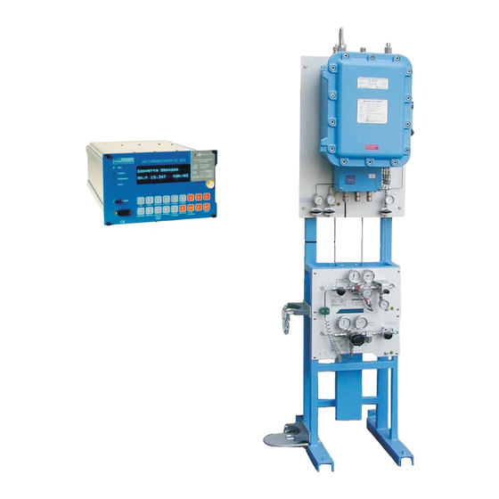
- Page 1 Gas Quality Measuring Device EMC 500 / 500-L OPERATING INSTRUCTIONS Serving the Gas Industry Worldwide by Honeywell STATUS FEBRUARY 2008...
- Page 2 (and those of other devices) from our website www.rmg.com. RMG Messtechnik GmbH Otto-Hahn-Str. 5 Phone numbers: 35510 Butzbach (Germany) Switchboard: +49 (0)6033 897-0 Fax: +49 (0)6033 897-130 Customer Service: +49 (0)6033 897-127 E-mail: Messtechnik@Honeywell.com Spare Parts: +49 (0)6033 897-173 ........................................... Manual EMC 500 · EN01 · 2008-02...
-
Page 3: Table Of Contents
Mechanical connection ......................10 Electrical connections ....................... 11 Connection box of the measuring element ................... 11 Terminal assignments for the EMC 500 design with analog transmission ..........11 Terminal diagram of the measuring element for digital transmission ............ 12 Warming-up phase ........................13 Initial calibration ........................ - Page 4 B Technical Data ........................49 C Pin Assignment Diagram for the GC 9000 ................51 D Fault List ..........................52 E Configuration of the Interfaces ................... 55 F Assembly Instructions for Pipe Connections ..............56 ........................................... Manual EMC 500 · EN01 · 2008-02...
-
Page 5: Introduction
The version EMC 500-L is also suitable for natural gases which have been conditioned with up to 20% of air. This version may be used for custody transfer flow measurements of the superior calorific value and the CO content. -
Page 6: Operating Principle
......................................... Operating principle At the heart of the EMC 500 measuring device lie two thermal sensors depending on the type of gas used which are used to measure the heat capacity and thermal conductivity of the gas. Since these two quantities represent over a wide range a function of the superior calorific value, it is possible to calculate the superior and inferior calorific values from these measured values. -
Page 7: Construction Of The Explosion-Protected (Ex) Design
Inlet pressure 0.5 to 3.0 bar B: Calibration gas inlet 1/8” pipe connection with Swagelok joint C: Test gas inlet E1, E2: Outlet pipes with 6 mm pipe connections with Swagelok joints ........................................... Manual EMC 500 · EN01 · 2008-02... -
Page 8: Construction Of The Not Explosion-Protected (Non Ex) Design
Inlet pressure 0.5 to 3.0 bar B: Calibration gas inlet 1/8” pipe connection with Swagelok joint C: Test gas inlet E1, E2: Outlet pipes with 6 mm pipe connections with Swagelok joints ........................................... Manual EMC 500 · EN01 · 2008-02... -
Page 9: Measuring And Electronic Unit
7. Mounting plate 3. Pressure transducer 8. Power supply unit 4. Infrared sensor (CO ) (only active in 230 V version) 5. Solenoid valve block 9. Electronic board with 3/2-way solenoid valve ........................................... Manual EMC 500 · EN01 · 2008-02... -
Page 10: Sensor Block
Connection of pressure compensation Gas outlet Heating mat Capillary tube spiral (flow resistor) Cover for gas preheating plate, all-round welded to be gas-tight. Flow sensor p pressure sensor Heating mat Gas preheating plate ........................................... Manual EMC 500 · EN01 · 2008-02... -
Page 11: Complete Configuration
GC-Mode Output Input Max. Cal. Val. GC-Status Print Coordinate Fault Enter Comp. Values S.Density Select Clear Wobbe RS232 RS485 D(A) D(B) T(A) T(B) Coupling element Measuring element Analytical computer ........................................... Manual EMC 500 · EN01 · 2008-02... -
Page 12: Operating Instructions For The Explosion-Protected Design
Protected Design General Instructions The explosion-protected design of the EMC 500 superior salorific value, standard density and Wobbe index measuring device is an explosion-protected electrical apparatus of the “explosion- proof encapsulation” type of protection with a terminal compartment of the “increased-safety” type of protection. -
Page 13: Maintenance
If repairs are done by the manufacturer, they need not be approved by an expert..........................................Manual EMC 500 · EN01 · 2008-02... -
Page 14: Start-Up
-20°C and must not rise to more than +55°C. Mechanical connection The EMC 500 has two gas inlets (one for the measuring gas and the other for the calibration gas) and one gas outlet. In addition, a bypass is installed which can be connected in the event of long supply lines and high pressures in order to reduce reaction time. -
Page 15: Electrical Connections
Connection box of the measuring element Screw secured Cover plate with locking seal secured PE 1 2 3 4 5 6 7 8 11 12 PE PE Terminal assignments for the EMC 500 design with analog transmission Measuring Analytical Signal element computer terminal... -
Page 16: Terminal Diagram Of The Measuring Element For Digital Transmission
START-UP ......................................... Terminal diagram of the measuring element for digital transmission ........................................... Manual EMC 500 · EN01 · 2008-02... -
Page 17: Warming-Up Phase
This is mainly due to the following reasons: - The sensor block of the EMC 500, where the sensors and the pressure regulators are located, is heated at a constant temperature of approx. +65°C. The warming-up phase is necessary to heat up the interior. -
Page 18: Operation
Operation Automatic recalibration Using the automatic recalibration feature, you can calibrate the EMC 500 either by pressing the appropriate key or at selectable intervals via its internal clock. For custody transfer applications the calibration interval may not exceed 4 weeks. -
Page 19: Sequence Of Calibration
"Test Gas OFF" for completion. In any case a test gas analysis can maximally last as long as specified in coordinate M 13 as time limit (in minutes). Afterwards the EMC 500 switches back to measuring gas analysis. The results of the test gas analysis are displayed in M 14 to M 24. -
Page 20: Analytical Computer Gc 9000
CPU continues to carry out all measuring tasks. An interface module has been plugged onto the back of this CPU in order to provide the device with another four data interfaces..........................................Manual EMC 500 · EN01 · 2008-02... - Page 21 - With the DSfG version no storage of the measured values takes place. For storage of the measured values the data logger MRG 2203, approved for custody transfer application, is available. The software of this device is specifically adapted to the EMC 500. The software version is to be read in Y 24.
-
Page 22: Gc 9000 Front Panel
On the ID plate you find, among other things the serial number of the measuring element. Since the operating parameters are adjusted to the measuring element and stored in the analytical, operation is only possible if the analytical computer is connected to the appropriate measuring element! ........................................... Manual EMC 500 · EN01 · 2008-02... -
Page 23: Operating The Gc 9000
Indication calibration status and when pressing the keys all values related to the calibration status incl. start and results ± , Calibration report, data report, revision report ........................................... Manual EMC 500 · EN01 · 2008-02... -
Page 24: Special Function Keys
To switch over from short designations to coordinates and vice versa. Switching over is possible in almost all fields (also in the programming mode). Release of special functions (according to instructions on the display) ........................................... Manual EMC 500 · EN01 · 2008-02... -
Page 25: Display Fault / Clear Fault Function
Press key 9 (Cal. Val.) EMC Measured values 10.123 kWh/m3 Press EMC Measured values *rho,n 0.6478 kg/m3 Press EMC Measured values 13.254 kWh/m3 Press EMC Select calculation EMC-rn Press EMC Select calculation EMC-d ........................................... Manual EMC 500 · EN01 · 2008-02... -
Page 26: Enabling Programming
ENTER key. The brightness of the bottom line is reduced to indicate that access to the coordinate field is enabled..........................................Manual EMC 500 · EN01 · 2008-02... -
Page 27: Programming A New Constant
For values in exponential representation the "E" is entered by pressing the ± key. For this purpose it is necessary that a comma has been entered before. So for example the input of 3E-5 is not possible but it must be entered 3.0E-5..........................................Manual EMC 500 · EN01 · 2008-02... -
Page 28: Programming A New Mode
7. Select "Wobbeindex" in field F7 with the keys. 8. Press the Enter key. Now the limits for the Wobbe index at 4 and 20 mA remain to be inputted..........................................Manual EMC 500 · EN01 · 2008-02... -
Page 29: Coordinate System Gc 9000
measurement temperature sensor temperature sensor (lines 10-16, 43), (lines 2-37) (lines 2-37) (lines 2-40) status of the interfaces (lines 31-42) Page ........................................... Manual EMC 500 · EN01 · 2008-02... -
Page 30: Description Of The Matrix Structure
S = Data which can be modified via Designation of the line in a column. The headline is not displayed in coordinate representation. Bold text shows important fields! ........................................... Manual EMC 500 · EN01 · 2008-02... -
Page 31: Description Of Individual Columns
Temperature at base cond. sup. calorif. value 0°C /15°C / 20°C / 25°C 1) In this field a manual calibration can be started with the "*" key if the code number has been inputted before (see display text)..........................................Manual EMC 500 · EN01 · 2008-02... -
Page 32: Emc Constants
Parameter F0 EMC inferior calorific value S Hi-Z0 Parameter Z0 EMC inferior calorific value S CH-C1 Parameter C1 EMC hydrocarbons … S … … S CH-C7 Parameter C7 EMC hydrocarbons 1) Value in exponential notation ........................................... Manual EMC 500 · EN01 · 2008-02... -
Page 33: Emc Mode
(see field D-24). For hour- or minute-based intervals, the time of synchronization is the next change of hour or minute, independently of the weekday and the starting time. As soon as the time of synchronization has been reached, no calibration will be initiated..........................................Manual EMC 500 · EN01 · 2008-02... -
Page 34: Emc Archives
D Hsc Current GC-corrected superior calorific value s. K/21 D rnc Current GC-corrected standard density kg/m3 D CO2c Current GC-corrected CO2 content s. K/24 D Wsc Current GC-corrected Wobbe index s. K/22 ........................................... Manual EMC 500 · EN01 · 2008-02... -
Page 35: Current Output 1
3) If a fault occurs, the current displayed will not correspond to the converted physical value. Depending on the set mode, the current will be calculated from the default value or the last measured value, or it will be zero..........................................Manual EMC 500 · EN01 · 2008-02... -
Page 36: Current Output 2
3) If a fault occurs, the current displayed will not correspond to the converted physical value. Depending on the set mode, the current will be calculated from the default value or the last measured value, or it will be zero..........................................Manual EMC 500 · EN01 · 2008-02... -
Page 37: Current Output 3
3) If a fault occurs, the current displayed will not correspond to the converted physical value. Depending on the set mode, the current will be calculated from the default value or the last measured value, or it will be zero..........................................Manual EMC 500 · EN01 · 2008-02... -
Page 38: Current Output 4
3) If a fault occurs, the current displayed will not correspond to the converted physical value. Depending on the set mode, the current will be calculated from the default value or the last measured value, or it will be zero..........................................Manual EMC 500 · EN01 · 2008-02... -
Page 39: Serial Interfaces
Port C2 baudrate: 9600 / 19200 / 38400 D RS_C3 Heading serial data interface C3 S C3-Type Port C3 type: OFF / MB-Sl.ASCII / MB-Sl.RTU / RMG bus S C3-Baud Port C3 baudrate: 9600 / 19200 S C3-Bits Port C3 number of bits: 7 / 8... -
Page 40: Selection Of Calculations
D FrnL Last valid EMC standard density kg/m3 D FdL Last valid EMC relative density D FHiL Last valid EMC inferior calorific value s. K/23 D FCO2L Last valid EMC carbon dioxide content ........................................... Manual EMC 500 · EN01 · 2008-02... -
Page 41: Measured Values
Lower fault limit, carbon dioxide content s. K/24 S CO2max Upper fault limit, carbon dioxide content s. K/24 C CO2-def Default value, carbon dioxide content s. K/24 S CO2-af Averaging factor (damping), carbon dioxide content ........................................... Manual EMC 500 · EN01 · 2008-02... - Page 42 S CH-af Averaging factor (damping), hydrocarbon content S MN-min Lower fault limit, methane number S MN-max Upper fault limit, methane number 1) For fiscal metering in the mode EMC 500 (see Y25)..........................................Manual EMC 500 · EN01 · 2008-02...
-
Page 43: Printer Control
C LPT-EMC EMC data report sensors Print OFF / Print ON C AutoRep EMC automatic print repetition rate C Rev-Rep EMC revision print repetition rate D L-P Time of last EMC printout ........................................... Manual EMC 500 · EN01 · 2008-02... -
Page 44: Date
Column Q Description of coordinates Unit Comment(s) D Time Heading of time display C Time: Time display D UnixS Unix seconds since 01.01.1970 00:00 D UnixT Date and time of Unix Time ........................................... Manual EMC 500 · EN01 · 2008-02... -
Page 45: Fault
D 3202 Measuring element error, bit string 3 D 3203 Measuring element error, bit string 4 D Warn-fl Warning flag D Fault-fl Fault flag D E-idx Index events archive D E-Arch. Events archive ........................................... Manual EMC 500 · EN01 · 2008-02... -
Page 46: Emc Sensor 1
Sensor 1 offset, base calibration D Off-D1 Sensor 1 diff. with regard to base calib. D S1-1112 Measured value read from EMC, sensor 1 D S1-1012 Analog value read from EMC, sensor 1 ........................................... Manual EMC 500 · EN01 · 2008-02... -
Page 47: Emc Sensor 2
Sensor 2 offset, base calibration D Off-D2 Sensor 2 diff. with regard to base calib. D S2-1114 Measured value read from EMC, sensor 2 D S2-1014 Analog value read from EMC, sensor 2 ........................................... Manual EMC 500 · EN01 · 2008-02... -
Page 48: Emc Pressure
Measured value read from EMC, output pressure P1 D p1-1002 Analog value read from EMC, output pressure P1 D dp-1104 Measured value read from EMC, differential pressure DP D dp-1004 Analog value read from EMC, differential pressure DP ........................................... Manual EMC 500 · EN01 · 2008-02... -
Page 49: Emc Case Temperature
Mode EMC case temperature S tC-Spec Specified value, EMC case temperature °C D tC-1106 Measured value read from EMC, case temperature TC D tC-1006 Analog value read from EMC, case temperature TC ........................................... Manual EMC 500 · EN01 · 2008-02... -
Page 50: Emc Block Temperature
1) The changed setting will only become effective after a restart of the analytical computer 2) Attention: Input 0 is only allowed for testing operations. In normal measuring mode, start time 2 must be unequal 0! ........................................... Manual EMC 500 · EN01 · 2008-02... -
Page 51: Version Parameters
For natural gases which have been conditioned with air: EMC 500-L (calorific value and CO2 for custody transfer flow measurements; standard density after special test for calculation of K number) Calculated methane number with GC-corrected values. The methane number can only be calculated within the following ranges: Hs: 8.33 –... -
Page 52: Annex
Data interface C2 inactive Modbus Data interface C3 (ASCII) RMG bus Data interface C4 (ASCII) Measuring Data interface C5 element Power supply for 24 V DC or 230 V AC ........................................... Manual EMC 500 · EN01 · 2008-02... -
Page 53: B Technical Data
C2 interface RS 485 (inactive) or DSfG C3 interface RS 232 modbus (max. distance 15 m) C4 interface RS 485 RMG bus (changeable to RS 232) C5 interface RS 232 for communication with measuring element transmission rates from 1200 to 38400 bd... - Page 54 B x H x T = 475 x 720 x 340 mm IP 54 (Ex design) Degree of protection: IP 43 (Non-Ex design) 0.5-3.0 bar Inlet pressure range: Gas consumption: max. 15 N/h ........................................... Manual EMC 500 · EN01 · 2008-02...
-
Page 55: C Pin Assignment Diagram For The Gc 9000
ANNEX ......................................... Pin Assignment Diagram for the GC 9000 C3: Modbus-Slave C5: EMC-Modbus-Master C1: LPT C2: DSfG C4: Modbus-Slave ........................................... Manual EMC 500 · EN01 · 2008-02... -
Page 56: D Fault List
EMC TB Failure EMC block temperature failure 21-1 EMC TB MaxRange Block temperature above max limit 21-2 EMC TB MinRange Block temperature below min limit 22-0 EMC Calib. Gas Calibration gas fault ........................................... Manual EMC 500 · EN01 · 2008-02... - Page 57 EMC500 AD Fault Fault A/D measurements EMC 500 59-2 EMC500 IO Error Fault I/O signals EMC 500 59-3 EMC500 MV Fault Fault measured values EMC 500 76-5 Modb.Failure C5 Modbus failure C5 ........................................... Manual EMC 500 · EN01 · 2008-02...
- Page 58 MB Busy C5 No response because device is busy, modbus C5 85-6 MB Neg.Ack. C5 Enquired function can not be started, modbus C5 85-7 MB Mem.Par. C5 Memory parity error modbus C5 ........................................... Manual EMC 500 · EN01 · 2008-02...
-
Page 59: E Configuration Of The Interfaces
C4 needs external terminating resistors and a bus supply voltage (+5 V). Select the mode for the interface C4 by the DIL switch 5 on the CPU card: DIL 5 ON: RS 485 DIL 5 OFF: RS 232 ........................................... Manual EMC 500 · EN01 · 2008-02... -
Page 60: F Assembly Instructions For Pipe Connections
* For pipe connections sized 2, 3, 4 mm or 1/16", 1/8", 3/16", you must tighten the nut with a ¾ turn during initial assembly. Removed fitting Insert pipe with clamping rings into fitting until stop is reached Tighten nut with fingers only, then use wrench to tighten it with approximately ¼ turn..........................................Manual EMC 500 · EN01 · 2008-02...
Need help?
Do you have a question about the EMC 500 and is the answer not in the manual?
Questions and answers