Table of Contents
Advertisement
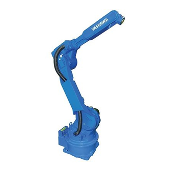
MOTOMAN-HP20D
MAINTENANCE MANUAL
TYPE:
YR-HP0020D-A00 (STANDARD SPECIFICATION FOR DX100)
YR-HP0020D-B00 (ZEROING SPECIFICATIONS FOR DX100)
YR-HP0020D-A10 (LONG U-ARM, 6kg PAYLOAD SPECIFICATION)
Procedures described in this maintenance manual should be carried out by the person who took the
maintenance-relevant trainings offered by YASKAWA.
Upon receipt of the product and prior to initial operation, read these instructions thoroughly, and retain
for future reference.
MOTOMAN INSTRUCTIONS
MOTOMAN-HP20D INSTRUCTIONS
DX100 INSTRUCTIONS
DX100 OPERATOR'S MANUAL
DX100 MAINTENACE MANUAL
The DX100 operator's manual above corresponds to specific usage.
Be sure to use the appropriate manual.
Part Number:
159281-1CD
Revision:
1
MANUAL NO.
HW1480357
1 of 96
3
Advertisement
Table of Contents

Related Manuals for YASKAWA MOTOMAN-HP20D


Summary of Contents for YASKAWA MOTOMAN-HP20D
- Page 1 YR-HP0020D-A10 (LONG U-ARM, 6kg PAYLOAD SPECIFICATION) Procedures described in this maintenance manual should be carried out by the person who took the maintenance-relevant trainings offered by YASKAWA. Upon receipt of the product and prior to initial operation, read these instructions thoroughly, and retain for future reference.
- Page 2 Copyright © 2018, 2011 Yaskawa America, Inc. Terms of Use and Copyright Notice All rights reserved. This manual is freely available as a service to Yaskawa customers to assist in the operation of Motoman robots, related equipment and software This manual is copyrighted property of Yaskawa and may not be sold or redistributed in any way.
-
Page 3: Table Of Contents
159281-1CD HP20D Table of Contents Table of Contents 1 Introduction ............................. 1-1 1.1 National Safety Standard for Industrial Robots and Robot Systems ......... 1-2 1.2 Notes for Safe Operation ....................1-3 1.3 Definition of Terms Used Often in This Manual ..............1-5 1.4 Registered Trademark ....................... - Page 4 159281-1CD HP20D Table of Contents 4 Grease Replenishment and Exchange ................... 4-1 4.1 Notes on Grease Replenishment and Exchange Procedures ........... 4-1 4.2 Grease Replenishment and Exchange for S-Axis Speed Reducer........4-2 4.2.1 Grease Replenishment ..................4-2 4.2.2 Grease Exchange ....................4-3 4.3 Grease Replenishment and Exchange for L-Axis Speed Reducer ........
- Page 5 159281-1CD HP20D Table of Contents 8 Disassembly, Reassembly, and Adjustment of B- and T-axis Timing Belts........8-1 8.1 Disassembly and Reassembly of B- and T-axis Timing Belts ........... 8-1 8.2 Adjustment of Timing Belts ....................8-3 8.2.1 B-Axis ........................8-3 8.2.2 T-Axis ........................
-
Page 6: Introduction
If such modification is made, the manual number will also be revised. • If your copy of the manual is damaged or lost, contact a YASKAWA representative to order a new copy. The representatives are listed on the back cover. Be sure to tell the representative the manual number listed on the front cover. -
Page 7: National Safety Standard For Industrial Robots And Robot Systems
ALLOW UNTRAINED PERSONNEL TO OPERATE, PROGRAM, OR REPAIR THE EQUIPMENT! We recommend approved Yaskawa training courses for all personnel involved with the operation, programming, or repair of the equipment. This equipment has been tested and found to comply with the limits for a Class A digital device, pursuant to part 15 of the FCC rules. -
Page 8: Notes For Safe Operation
Failure to observe this caution may result in electric shock or injury. • For disassembly or repair, contact your Yaskawa representative. • Do not remove the motor, and do not release the brake. Failure to observe these safety precautions may result in death or serious injury from unexpected turning of the manipulator's arm. - Page 9 159281-1CD HP20D Introduction 1.2 Notes for Safe Operation WARNING • Before operating the manipulator, check that servo power is turned OFF pressing the emergency stop buttons. When the servo power is turned OFF, the SERVO ON LED on the programming pendant is turned OFF. Injury or damage to machinery may result if the emergency stop circuit cannot stop the manipulator during an emergency.
-
Page 10: Definition Of Terms Used Often In This Manual
Read and understand the Explanation of Warning Labels in the DX100 Instructions before operating the manipulator: Definition of Terms Used Often in This Manual The MOTOMAN is the YASKAWA industrial robot product. The MOTOMAN usually consists of the manipulator, the controller, the programming pendant, and supply cables. -
Page 11: Explanation Of Warning Labels
MOTOMAN- TYPE Moving parts PAYLOAD MASS may cause ORDER NO. DATE injury SERIAL NO. YASKAWA ELECTRIC CORPORATION 2-1 Kurosakishiroishi, Yahatanishi-ku, Kitakyushu 806-0004 Japan MADE IN JAPAN NJ3247 Warning Label B: WARNING Do not enter robot work area. 11 of 96... -
Page 12: Safeguarding Tips
159281-1CD HP20D Introduction 1.6 Safeguarding Tips Safeguarding Tips All operators, programmers, maintenance personnel, supervisors, and anyone working near the system must become familiar with the operation of this equipment. All personnel involved with the operation of the equipment must understand potential dangers of operation. General safeguarding tips are as follows: •... -
Page 13: Programming, Operation, And Maintenance Safety
Do not make any modifications to the controller unit. Making any changes without the written permission from Yaskawa will void the warranty. • Some operations require standard passwords and some require special passwords. -
Page 14: Maintenance Safety
Turn the power OFF and disconnect and lockout/tagout all electrical circuits before making any modifications or connections. Perform only the maintenance described in this manual. Maintenance other than specified in this manual should be performed only by Yaskawa- trained, qualified personnel. 1.10... -
Page 15: Customer Support Information
If you need assistance with any aspect of your HP20D system, please contact YASKAWA Customer Support at the following 24-hour telephone number: (937) 847-3200 For routine technical inquiries, you can also contact YASKAWA Customer Support at the following e-mail address: techsupport@motoman.com When using e-mail to contact YASKAWA Customer Support, please provide a detailed description of your issue, along with complete contact information. -
Page 16: Notes For Maintenance
159281-1CD HP20D Notes for Maintenance 2.1 Wrist Unit Notes for Maintenance • When performing maintenance such as replacement of a wire harness in the manipulator, the encoder connector may be necessary to be removed. In this case, be sure to connect the battery pack to the battery backup connector NOTE before removing the encoder connector. -
Page 17: Encoder Connector (With Caution Label)
159281-1CD HP20D Notes for Maintenance 2.2 Encoder Connector (with CAUTION Label) Encoder Connector (with CAUTION Label) Before disconnecting the encoder connector (with CAUTION label), connect the battery pack to the motor referring to Fig. 2-2 “Battery Pack Connection”. 2.2.1 Battery Pack Connection for S-, L-, and U-axis Motors The connectors (crimped contact-pin) for the battery backup are installed at the end point of the motor (BAT and OBT are marked). - Page 18 159281-1CD HP20D Notes for Maintenance 2.2 Encoder Connector (with CAUTION Label) Fig. 2-2: Battery Pack Connection Motor S-, L-, U-axis motor Encoder connector CAUTION Motor power connector Connect battery to encoder to save the data before removing connector. CAUTION label 0BT1 BAT1 Battery pack (HW9470932-A)
-
Page 19: Home Position Return
159281-1CD Home Position Return HP20D 3.1 Home Position Return after Motor Replacement Home Position Return Perform calibration and set the manipulator position in one of the following cases: • The combination of the MOTOMAN and the control unit is changed. •... -
Page 20: Home Position Return By Setting Teaching Point For Home Position Setting Before Motor Replacement
159281-1CD Home Position Return HP20D 3.1 Home Position Return after Motor Replacement 3.1.3 Home Position Return by Setting Teaching Point for Home Position Setting before Motor Replacement The DX100 holds the position data of the job program (hereinafter called JOB) as the pulse number from the home position of each axis. Thus, by adjusting the home position precisely, the JOB used before motor replacement can be used after the replacement without correction. - Page 21 159281-1CD Home Position Return HP20D 3.1 Home Position Return after Motor Replacement Example of Check-Point Creation when Replacing U-Axis’s Motor of HP20D-A00 • The check-point cannot be created unless each axis operates. Thus, the check-point cannot be created if the axis does not move because of failure.
-
Page 22: Motor Replacement
159281-1CD Home Position Return HP20D 3.1 Home Position Return after Motor Replacement 3.1.3.2 Motor Replacement • Refer to the Fig. 3-2 “Motor Replacement (Example)”. CAUTION • Since the motor is removed, the manipulator cannot keep its posture during motor replacement. When replacing the motor, hold the manipulator arm with the chain block, etc. -
Page 23: Home Position Adjustment
159281-1CD Home Position Return HP20D 3.1 Home Position Return after Motor Replacement 3.1.3.3 Home Position Adjustment After motor replacement, move the axis to the position of the home position mark. Perform the home position calibration only to the axis whose motor was replaced. (For more information, refer to “DX100 INSTRUCTIONS”... -
Page 24: Home Position Return In Case Of Exhaustion Of Robot-Axis Motor Battery
159281-1CD Home Position Return HP20D 3.2 Home Position Return in Case of Exhaustion of Robot-Axis Motor Battery Home Position Return in Case of Exhaustion of Robot-Axis Motor Battery 3.2.1 Home Position Return at the Time of Battery Backup by Using the Function: Home Position Calibration Function for Restoration To start the home position calibration function for restoration, move the manipulator to the posture close to the home position (within one motor... - Page 25 159281-1CD Home Position Return HP20D 3.2 Home Position Return in Case of Exhaustion of Robot-Axis Motor Battery L-Axis Positioning As shown in Fig. 3-4 “L-Axis Positioning”, insert the shaft SFJW6-100 in the hole ( ) on the S-head. Then, perform positioning with the +0.012 programming pendant so that the shaft fits into the hole on the L-arm.
- Page 26 159281-1CD Home Position Return HP20D 3.2 Home Position Return in Case of Exhaustion of Robot-Axis Motor Battery R-Axis Positioning As shown in Fig. 3-6 “R-Axis Positioning”, insert the shaft SFJW4-100 in the hole ( ) on the U-arm. Then, perform positioning with the +0.012 programming pendant so that the shaft fits into the hole on the casing.
-
Page 27: Grease Replenishment And Exchange
159281-1CD Grease Replenishment and Exchange HP20D 4.1 Notes on Grease Replenishment and Exchange Procedures Grease Replenishment and Exchange Notes on Grease Replenishment and Exchange Procedures Make sure to follow the instructions listed below at grease replenishment or exchange. Failure to observe the following notes may result in damage to the motor or speed reducer. -
Page 28: Grease Replenishment And Exchange For S-Axis Speed Reducer
159281-1CD Grease Replenishment and Exchange HP20D 4.2 Grease Replenishment and Exchange for S-Axis Speed Reducer Grease Replenishment and Exchange for S-Axis Speed Reducer Fig. 4-1: S-Axis Speed Reducer Grease exhaust port (Hexagon socket head plug PT1/8) Grease inlet S-axis speed reducer (Hexagon socket head plug PT1/8) For ceiling mounted manipulators, the exhaust port and the NOTE... -
Page 29: Grease Exchange
159281-1CD Grease Replenishment and Exchange HP20D 4.2 Grease Replenishment and Exchange for S-Axis Speed Reducer 4. Move the S-axis for a few minutes to discharge excess grease. 5. Remove the grease zerk from the grease inlet and reinstall the plug. Apply ThreeBond 1206C to the thread part of the plug, and tighten the plug with a tightening torque of 5 N•m (0.51 kgf•m). -
Page 30: Grease Replenishment And Exchange For L-Axis Speed Reducer
159281-1CD Grease Replenishment and Exchange HP20D 4.3 Grease Replenishment and Exchange for L-Axis Speed Reducer Grease Replenishment and Exchange for L-Axis Speed Reducer Fig. 4-2: L-Axis Speed Reducer Grease exhaust port (Hexagon socket head plug PT1/8) L-arm L-axis speed reducer Grease inlet (Hexagon socket head cap screw M6) 4.3.1 Grease Replenishment... -
Page 31: Grease Exchange
159281-1CD Grease Replenishment and Exchange HP20D 4.3 Grease Replenishment and Exchange for L-Axis Speed Reducer 4.3.2 Grease Exchange (Refer to Fig. 4-2 “L-Axis Speed Reducer”.) 1. Make the L-arm vertical to the ground. 2. Remove the hexagon socket head cap screw from the grease inlet and the hexagon socket head plug from the grease exhaust port. -
Page 32: Grease Replenishment And Exchange For U-Axis Speed Reducer
159281-1CD Grease Replenishment and Exchange HP20D 4.4 Grease Replenishment and Exchange for U-Axis Speed Reducer Grease Replenishment and Exchange for U-Axis Speed Reducer Fig. 4-3: U-Axis Speed Reducer U-arm Grease exhaust port (Hexagon socket head cap screw M6) U-axis speed reducer Grease inlet (Hexagon socket head plug PT1/8) For ceiling mounted manipulators, the exhaust port and the... -
Page 33: Grease Exchange
159281-1CD Grease Replenishment and Exchange HP20D 4.4 Grease Replenishment and Exchange for U-Axis Speed Reducer 4.4.2 Grease Exchange (Refer to Fig. 4-3 “U-Axis Speed Reducer”.) 1. Make the U-arm horizontal to the ground. 2. Remove the hexagon socket head plug from the grease inlet and the hexagon socket head cap screw from the grease exhaust port. -
Page 34: Grease Replenishment For R-Axis Speed Reducer
159281-1CD Grease Replenishment and Exchange HP20D 4.5 Grease Replenishment for R-Axis Speed Reducer Grease Replenishment for R-Axis Speed Reducer Fig. 4-4: R-Axis Speed Reducer Grease inlet (Grease zerk A-MT6 x 1) Exhaust port (Hexagon socket head cap screw M6) 1. Remove the hexagon socket head cap screw from the exhaust port. 2. -
Page 35: Grease Replenishment For B- And T-Axis Speed Reducers
159281-1CD Grease Replenishment and Exchange HP20D 4.6 Grease Replenishment for B- and T-Axis Speed Reducers Grease Replenishment for B- and T-Axis Speed Reducers Fig. 4-5: B- and T-Axis Speed Reducers B-axis exhaust port (Plug LP-M5) T-axis speed reducer T-axis exhaust port (Hexagon socket set screw M6) B-axis speed reducer T-axis grease inlet... -
Page 36: Grease Replenishment For T-Axis Gear
159281-1CD Grease Replenishment and Exchange HP20D 4.7 Grease Replenishment for T-Axis Gear Grease Replenishment for T-Axis Gear Fig. 4-6: T-Axis Gear Exhaust port (Plug LP-M5) Gear grease inlet (Hexagon socket head cap screw M6) 1. Remove the hexagon socket head cap screw from the grease inlet and the plug LP-M5 from the exhaust port. -
Page 37: Grease Replenishment For R-Axis Cross Roller Bearing
159281-1CD Grease Replenishment and Exchange HP20D 4.8 Grease Replenishment for R-Axis Cross Roller Bearing Grease Replenishment for R-Axis Cross Roller Bearing Fig. 4-7: R-Axis Cross Roller Bearing Exhaust port (Plug LP-M5) R-axis cross roller bearing Grease inlet (Hexagon socket head cap screw M6 x 6) 1. -
Page 38: Disassembly And Reassembly Of Motors
159281-1CD Disassembly and Reassembly of Motors HP20D 5.1 Disassembly and Reassembly of S-Axis Motor Disassembly and Reassembly of Motors Disassembly and Reassembly of S-Axis Motor • Refer to Fig. 5-1 “Disassembly and Reassembly of S-Axis Motor”. • Refer to chapter 3 “Home Position Return”, chapter 4 “Grease Replenishment and Exchange”, and chapter 8 “Disassembly, Reassembly, and Adjustment of B- and T- axis Timing Belts”. - Page 39 159281-1CD Disassembly and Reassembly of Motors HP20D 5.1 Disassembly and Reassembly of S-Axis Motor 6. Connect the power connector of the L-axis motor. Fix the connector on the motor side by using pliers, etc. when connecting the power connector. 7. Remove the backup battery. 8.
- Page 40 159281-1CD Disassembly and Reassembly of Motors HP20D 5.1 Disassembly and Reassembly of S-Axis Motor Fig. 5-1: Disassembly and Reassembly of S-Axis Motor 40 of 96 HW1480357...
-
Page 41: Disassembly And Reassembly Of L-Axis Motor
159281-1CD Disassembly and Reassembly of Motors HP20D 5.2 Disassembly and Reassembly of L-Axis Motor Disassembly and Reassembly of L-Axis Motor • Refer to Fig. 5-2 “Disassembly and Reassembly of L-Axis Motor”. Disassembly 1. Turn OFF the DX100 power supply, then drain grease. 2. - Page 42 159281-1CD Disassembly and Reassembly of Motors HP20D 5.2 Disassembly and Reassembly of L-Axis Motor Table 5-2: L-Axis Motor Parts Checklist Name Qty. Notes L-axis motor HW0387863-A SGMRV-13ANA-YR21 Hexagon socket head cap screw M8 Tightening torque: (length: 25 mm) each 24.5 N•m Conical spring washer 2H-8 M-base HW0304229-1 Input gear HW0313492-1...
-
Page 43: Disassembly And Reassembly Of U-Axis Motor
159281-1CD Disassembly and Reassembly of Motors HP20D 5.3 Disassembly and Reassembly of U-Axis Motor Disassembly and Reassembly of U-Axis Motor • Refer to Fig. 5-3 “Disassembly and Reassembly of U-Axis Motor”. Disassembly 1. Turn OFF the DX100 power supply, then drain grease. 2. - Page 44 159281-1CD Disassembly and Reassembly of Motors HP20D 5.3 Disassembly and Reassembly of U-Axis Motor Table 5-3: U-Axis Motor Parts Checklist Name Qty. Notes U-axis motor HW0387860-A SGMRV-05ANA-YR11 GT-SA bolt M8 Tightening torque: (length: 30 mm) 24.5 N•m Input Gear Hexagon socket head cap screw M5 Tightening torque: (length: 65 mm) each...
-
Page 45: Disassembly And Reassembly Of R-Axis Motor
159281-1CD Disassembly and Reassembly of Motors HP20D 5.4 Disassembly and Reassembly of R-Axis Motor Disassembly and Reassembly of R-Axis Motor • Refer to Fig. 5-4 “Disassembly and Reassembly of R-Axis Motor”. Disassembly 1. Turn OFF the DX100 power supply. 2. - Page 46 159281-1CD Disassembly and Reassembly of Motors HP20D 5.4 Disassembly and Reassembly of R-Axis Motor 10. Tighten the GT-SA bolts with the tightening torque shown in Table 5-4 "R-Axis Motor Parts Checklist". 11. Turn ON the DX100 power supply. Table 5-4: R-Axis Motor Parts Checklist Name Qty.
- Page 47 159281-1CD Disassembly and Reassembly of Motors HP20D 5.4 Disassembly and Reassembly of R-Axis Motor Fig. 5-4: Disassembly and Reassembly of R-Axis Motor Fill with Harmonic grease SK-1A. Apply ThreeBond 1206C. (See the step 3 of the R-axis (See the step 4 of the R-axis reassembly procedure.) reassembly procedure.) Casing...
-
Page 48: Disassembly And Reassembly Of B-Axis Motor
159281-1CD Disassembly and Reassembly of Motors HP20D 5.5 Disassembly and Reassembly of B-Axis Motor Disassembly and Reassembly of B-Axis Motor • Refer to Fig. 5-5 “Disassembly and Reassembly of B-Axis Motor”. Disassembly 1. Turn OFF the DX100 power supply. 2. - Page 49 159281-1CD Disassembly and Reassembly of Motors HP20D 5.5 Disassembly and Reassembly of B-Axis Motor Table 5-5: B-Axis Motor Parts Checklist Name Qty. Notes B-axis motor HW0389298-A SGMPH-02ANA-YR11 GT-SA bolt M5 Tightening torque: (length: 20 mm) 6 N•m Pulley HW9482727-A Hexagon socket head cap screw M4 Tightening torque: (length: 16 mm) each...
-
Page 50: Disassembly And Reassembly Of T-Axis Motor
159281-1CD Disassembly and Reassembly of Motors HP20D 5.6 Disassembly and Reassembly of T-Axis Motor Disassembly and Reassembly of T-Axis Motor • Refer to Fig. 5-6 “Disassembly and Reassembly of T-Axis Motor”. Disassembly 1. Turn OFF the DX100 power supply. 2. - Page 51 159281-1CD Disassembly and Reassembly of Motors HP20D 5.6 Disassembly and Reassembly of T-Axis Motor Table 5-6: T-Axis Motor Parts Checklist Name Qty. Notes T-axis motor HW0389298-A SGMPH-02ANA-YR11 GT-SA bolt M5 Tightening torque: (length: 20 mm) 6 N•m Pulley HW9482727-A Hexagon socket head cap screw M4 Tightening torque: (length: 16 mm) each...
-
Page 52: Disassembly And Reassembly Of Speed Reducer
159281-1CD Disassembly and Reassembly of Speed Reducer HP20D 6.1 Disassembly and Reassembly of S-Axis Speed Reducer Disassembly and Reassembly of Speed Reducer Disassembly and Reassembly of S-Axis Speed Reducer • Refer to Fig. 6-1 “Disassembly and Reassembly of S-Axis Speed Reducer”. - Page 53 159281-1CD Disassembly and Reassembly of Speed Reducer HP20D 6.1 Disassembly and Reassembly of S-Axis Speed Reducer 6. Apply ThreeBond 1206C on the matching surface between the S-axis motor and the M-base . Then, mount the S-axis motor . (Perform the steps 3 to 6 of “Reassembly” in section 5.1 “Disassembly and Reassembly of S-Axis Motor”.) 7.
-
Page 54: Disassembly And Reassembly Of L-Axis Speed Reducer
159281-1CD Disassembly and Reassembly of Speed Reducer HP20D 6.2 Disassembly and Reassembly of L-Axis Speed Reducer Disassembly and Reassembly of L-Axis Speed Reducer • Refer to Fig. 6-2 “Disassembly and Reassembly of L-Axis Speed Reducer”. Disassembly 1. Turn OFF the DX100 power supply, then drain grease. 2. - Page 55 159281-1CD Disassembly and Reassembly of Speed Reducer HP20D 6.2 Disassembly and Reassembly of L-Axis Speed Reducer Fig. 6-2: Disassembly and Reassembly of L-Axis Speed Reducer S-head L-axis motor Internal wiring harness Input gear 55 of 96 HW1480357...
-
Page 56: Disassembly And Reassembly Of U-Axis Speed Reducer
159281-1CD Disassembly and Reassembly of Speed Reducer HP20D 6.3 Disassembly and Reassembly of U-Axis Speed Reducer Disassembly and Reassembly of U-Axis Speed Reducer • Refer to Fig. 6-3 “Disassembly and Reassembly of U-Axis Speed Reducer”. Disassembly 1. Turn OFF the DX100 power supply, then drain grease. 2. - Page 57 159281-1CD Disassembly and Reassembly of Speed Reducer HP20D 6.3 Disassembly and Reassembly of U-Axis Speed Reducer Table 6-3: U-Axis Speed Reducer Parts Checklist Name Qty. Notes Speed reducer HW9280880-G GT-SA bolt M8 Tightening torque: (length: 45 mm) 26.5 N•m Hexagon socket head cap screw M14 Tightening torque: (length: 35 mm) each...
-
Page 58: Disassembly And Reassembly Of R-Axis Speed Reducer
159281-1CD Disassembly and Reassembly of Speed Reducer HP20D 6.4 Disassembly and Reassembly of R-Axis Speed Reducer Disassembly and Reassembly of R-Axis Speed Reducer • Refer to Fig. 6-4 “Disassembly and Reassembly of R-Axis Speed Reducer”. Disassembly 1. Turn OFF the DX100 power supply. 2. - Page 59 159281-1CD Disassembly and Reassembly of Speed Reducer HP20D 6.4 Disassembly and Reassembly of R-Axis Speed Reducer Table 6-4: R-Axis Speed Reducer Parts Checklist Name Qty. Notes Speed reducer Circular spline HW0381463-A Speed reducer Flex spline HW0381463-A Speed reducer Wave generator HW0381463-A Shaft HW0404403-1 GT-SA bolt M6...
-
Page 60: Disassembly And Reassembly Of B-Axis Speed Reducer
159281-1CD Disassembly and Reassembly of Speed Reducer HP20D 6.5 Disassembly and Reassembly of B-Axis Speed Reducer Disassembly and Reassembly of B-Axis Speed Reducer • Refer to Fig. 6-5 “Disassembly and Reassembly of B-Axis Speed Reducer”. Disassembly 1. Turn OFF the DX100 power supply. 2. - Page 61 159281-1CD Disassembly and Reassembly of Speed Reducer HP20D 6.5 Disassembly and Reassembly of B-Axis Speed Reducer 13. Turn ON the DX100 power supply. Table 6-5: B-Axis Speed Reducer Parts Checklist Name Qty. Notes Speed reducer Flex spline HW9381633-A Speed reducer Circular spline HW9381633-A Speed reducer...
- Page 62 159281-1CD Disassembly and Reassembly of Speed Reducer HP20D 6.5 Disassembly and Reassembly of B-Axis Speed Reducer Fig. 6-5: Disassembly and Reassembly of B-Axis Speed Reducer B-axis motor Wrist base U-arm 6-11 62 of 96 HW1480357...
-
Page 63: Disassembly And Reassembly Of T-Axis Speed Reducer
159281-1CD Disassembly and Reassembly of Speed Reducer HP20D 6.6 Disassembly and Reassembly of T-Axis Speed Reducer Disassembly and Reassembly of T-Axis Speed Reducer • Refer to Fig. 6-6 “Disassembly and Reassembly of T-Axis Speed Reducer”. Disassembly 1. Turn OFF the DX100 power supply. 2. - Page 64 159281-1CD Disassembly and Reassembly of Speed Reducer HP20D 6.6 Disassembly and Reassembly of T-Axis Speed Reducer 11. Apply Harmonic Grease SK-1A on the surface between the teeth of the circular spline and the flex spline . Apply ThreeBond 1206C on the matching surface between the housing and the circular spline .
- Page 65 159281-1CD Disassembly and Reassembly of Speed Reducer HP20D 6.6 Disassembly and Reassembly of T-Axis Speed Reducer Fig. 6-6: Disassembly and Reassembly of T-Axis Speed Reducer Wrist base Flange 6-14 65 of 96 HW1480357...
-
Page 66: Disassembly And Reassembly Of Wrist Unit
159281-1CD Disassembly and Reassembly of Wrist Unit HP20D Disassembly and Reassembly of Wrist Unit • Refer to Fig. 7-1 “Disassembly and Reassembly of Wrist Unit”. Refer to chapter 2 “Notes for Maintenance”, chapter 3 NOTE “Home Position Return”, and chapter 10 “Cable Wiring”. Disassembly ... - Page 67 159281-1CD Disassembly and Reassembly of Wrist Unit HP20D Table 7-1: Wrist Unit Parts Checklist Name Qty. Notes Wrist unit Mass: 14.5 kg Hexagon socket head cap screw M6 Tightening torque: (length: 65 mm) each 10 N•m Conical spring washer 2H-6 Support HW9406556-1 GT-SA bolt M4 Tightening torque:...
-
Page 68: Disassembly, Reassembly, And Adjustment Of B- And T-Axis Timing Belts
159281-1CD Disassembly, Reassembly, and Adjustment of B- and T-axis Timing HP20D Belts 8.1 Disassembly and Reassembly of B- and T-axis Timing Belts Disassembly, Reassembly, and Adjustment of B- and T-axis Timing Belts Disassembly and Reassembly of B- and T-axis Timing Belts •... - Page 69 159281-1CD Disassembly, Reassembly, and Adjustment of B- and T-axis Timing HP20D Belts 8.1 Disassembly and Reassembly of B- and T-axis Timing Belts Table 8-1: B- and T-Axis Timing Belt Parts Checklist Name Qty. Notes B-axis timing belt 80S4.5M653 T-axis timing belt 80S4.5M518 T-axis motor HW0389298-A SGMPH-02ANA-YR11 GT-SA bolt M5...
-
Page 70: Adjustment Of Timing Belts
159281-1CD Disassembly, Reassembly, and Adjustment of B- and T-axis Timing HP20D Belts 8.2 Adjustment of Timing Belts Adjustment of Timing Belts 8.2.1 B-Axis 1. Loosen the GT-SA bolts shown in Fig. 8-1 “Disassembly and Reassembly of B- and T-Axis Timing Belts”. 2. -
Page 71: Battery Pack Replacement
159281-1CD Battery Pack Replacement HP20D Battery Pack Replacement The battery packs are installed in the position shown in Fig. 9-1 “Battery Pack Location”. If the battery alarm occurs in the DX100, replace the battery in accordance with the following procedure: Fig. - Page 72 159281-1CD Battery Pack Replacement HP20D Fig. 9-2: Battery Pack Connection Battery pack before replacement See the step 5 Connector Circuit board See the step 4 New battery pack (HW0470360-A) 1. Turn OFF the DX100 main power supply. 2. Remove the plate on the connector base, then pull the battery pack out to replace it with the new one.
-
Page 73: Cable Wiring
159281-1CD Cable Wiring HP20D 10.1 Disconnecting Cables 10 Cable Wiring To prevent loss of the encoder absolute data, make sure to connect the new battery pack before disconnecting the NOTE encoder cable connectors. (Refer to chapter 2 “Notes for Maintenance”.) 10.1 Disconnecting Cables 10.1.1 Cables in Wrist Unit... - Page 74 159281-1CD Cable Wiring HP20D 10.1 Disconnecting Cables Fig. 10-1: B- and T- Axis Cable Wiring B-axis internal wiring harness, T-axis internal wiring harness, Wrist unit connector connector B- and T-axis internal wiring harness B-axis motor T-axis motor 10-2 74 of 96 HW1480357...
-
Page 75: Cables In U-Arm
159281-1CD Cable Wiring HP20D 10.1 Disconnecting Cables 10.1.2 Cables in U-Arm • Refer to Table 10-2 "U-Arm Cable Wiring Parts Checklist" and Fig. 10-2 “U-Arm Cable Wiring”. 1. Remove the GT-SA bolts , then remove the cover . 2. Connect the backup batteries to the U- and R-axis motors. 3. - Page 76 159281-1CD Cable Wiring HP20D 10.1 Disconnecting Cables Table 10-2: U-Arm Cable Wiring Parts Checklist Name Qty. Notes Cover HW0305305-1 GT-SA bolt M6 Tightening torque: (length: 20 mm) 10 N•m Cross head APS bolt M4 (length: 10 mm) Pan-head sems screw M3 (length: 16 mm) each Nut M3...
- Page 77 159281-1CD Cable Wiring HP20D 10.1 Disconnecting Cables Fig. 10-2: U-Arm Cable Wiring 10-5 77 of 96 HW1480357...
-
Page 78: Cables In S-Head
159281-1CD Cable Wiring HP20D 10.1 Disconnecting Cables 10.1.3 Cables in S-Head • Refer to Table 10-3 "S-Head Cable Wiring Parts Checklist" and Fig. 10-3 “S-Head Cable Wiring”. 1. Remove the cross head APS bolts , then remove the cover . Then, cut off the cable tie which fixes the internal wiring harness. - Page 79 159281-1CD Cable Wiring HP20D 10.1 Disconnecting Cables Table 10-3: S-Head Cable Wiring Parts Checklist Name Qty. Notes Cover HW0304227-1 Cross head APS bolt M6 (length: 8 mm) Cover HW0305809-1 Cross head APS bolt M5 (length: 10 mm) GT-SA bolt M6 Tightening torque: (length: 15 mm) 10 N•m...
- Page 80 159281-1CD Cable Wiring HP20D 10.1 Disconnecting Cables Fig. 10-3: S-Head Cable Wiring S-axis connector Internal wiring harness L-axis motor S-head S-axis motor Cable ties (2 pieces) T18S Apply sealing bond to the hatched area. 10-8 80 of 96 HW1480357...
-
Page 81: Connecting Cables
159281-1CD Cable Wiring HP20D 10.2 Connecting Cables 10.2 Connecting Cables 10.2.1 Cables in S-Head • Refer to Table 10-3 "S-Head Cable Wiring Parts Checklist" and Fig. 10-3 “S-Head Cable Wiring”. 1. Run the internal wiring harness to which the C-base is attached through the S-head from the back of the manipulator. -
Page 82: Cables In U-Arm
159281-1CD Cable Wiring HP20D 10.2 Connecting Cables 10.2.2 Cables in U-Arm • Refer to Table 10-2 "U-Arm Cable Wiring Parts Checklist" and Fig. 10-2 “U-Arm Cable Wiring”. 1. Hold the spring part (the second or third coil from the end of the spring) of the B- and T-axis internal wiring harness by using the saddles . -
Page 83: Cables In Wrist Unit
159281-1CD Cable Wiring HP20D 10.2 Connecting Cables 19. Apply ThreeBond 1206C to the matching surface between the cover and the casing. Tighten the GT-SA bolts with the tightening torque shown in Table 10-2 "U-Arm Cable Wiring Parts Checklist". 10.2.3 Cables in Wrist Unit •... -
Page 84: Parts List
159281-1CD Parts List HP20D 11.1 S-Axis Unit 11 Parts List 11.1 S-Axis Unit Fig. 11-1: S-Axis Unit 1008 1001 1011 1012 1010 1034 1013 1036 1031 1035 1020 1032 1014 1022 1024 1023 1021 1030 1026 1009 1024 1023 1027 1033 1030 1002... - Page 85 159281-1CD Parts List HP20D 11.1 S-Axis Unit Table 11-1: S-Axis Unit DWG No. Name Pcs. 1001 SGMRV-09ANA-YR1* Motor 1002 HW0100545-2 S-head 1003 M16X20 Socket screw 1004 2H-16 Conical spring washer 1005 HW0387753-B Speed reducer 1006 M10X40 GT-SA bolt 1007 HW0100544-2 Base 1008 M8X30...
-
Page 86: L-Axis Unit
159281-1CD Parts List HP20D 11.2 L-Axis Unit 11.2 L-Axis Unit Fig. 11-2: L-Axis Unit 2024 2025 2001 2023 2017 2005 2004 2003 2008 2011 2002 2006 2019 2007 2018 2012 2010 2009 2028 2032 2026 2027 2014 2013 2022 2021 2020 2014 2013... - Page 87 159281-1CD Parts List HP20D 11.2 L-Axis Unit Table 11-2: L-Axis Unit DWG No. Name Pcs. 2001 SGMRV-13ANA-YR2* Motor 2002 M6X90 Socket screw 2003 2H-6 Conical spring washer 2004 HW0313492-1 Gear 2005 HW0304229-1 M-base 2006 Y426012.5 Oil seal 2007 HW0401506-1 Plate 2008 HW0304226-1 Support...
-
Page 88: U-Axis Unit
159281-1CD Parts List HP20D 11.3 U-Axis Unit 11.3 U-Axis Unit Fig. 11-3: U-Axis Unit 3003 3004 3002 3003 3004 3001 3005 3020 3002 3019 3019 3012 3016 3018 3006 3017 2017 3016 3009 3018 3008 3017 3011 3010 3007 3013 3015 3014 11-5... - Page 89 159281-1CD Parts List HP20D 11.3 U-Axis Unit Table 11-3: U-Axis Unit DWG No. Name Pcs. 3001 SGMRV-05A3A-YR1* Motor 3002 HW0313489-1 Cover 3003 M4X10 APS bolt 3004 Washer 3005 HW0102379-1 Casing 3006 HW9280880-G Speed reducer 3007 M8X45 GT-SA bolt 3008 M5X65 Socket screw 3009 2H-5...
-
Page 90: R-Axis Unit
159281-1CD Parts List HP20D 11.4 R-Axis Unit 11.4 R-Axis Unit Fig. 11-4: R-Axis Unit 4033 4012 4031 4032 4029 4071 4074 4036 4072 4010 4066 4030 4029 4008 3005 4042 4005 4058 4057 4035 4009 4056 4043 4006 4007 4044 4011 4003 4073... - Page 91 159281-1CD Parts List HP20D 11.4 R-Axis Unit Table 11-4: R-Axis Unit (Sheet 1 of 2) DWG No. Name Pcs. 4001 M6X65 Socket screw 4002 2H-6 Conical spring washer 4003 M5X20 GT-SA bolt 4004 M4X12 GT-SA bolt 4005 HW0305305-1 M-cover 4006 M4X20 Socket screw 4007...
- Page 92 159281-1CD Parts List HP20D 11.4 R-Axis Unit Table 11-4: R-Axis Unit (Sheet 2 of 2) DWG No. Name Pcs. 4051 M4X12 GT-SA bolt 4055 HW0404918-1 Support 4056 SGMPH-02A2A-YR1* Motor 4057 EZ5036A0 4058 M6X20 GT-SA bolt 4060 HW0304930-1 Support 4062 6811LLU Bearing 4065 M4X20...
-
Page 93: Wrist Unit
159281-1CD Parts List HP20D 11.5 Wrist Unit 11.5 Wrist Unit Fig. 11-5: Wrist Unit 3005 5045 5046 5005 5001 5002 5003 5006 5007 5011 5008 5008 5007 5045 5026 5044 5006 5037 5064 5003 5035 5043 5071 5005 5048 5038 5014 5039 5019... - Page 94 159281-1CD Parts List HP20D 11.5 Wrist Unit Table 11-5: Wrist Unit (Sheet 1 of 2) DWG No. Name Pcs. 5001 HW9406556-1 Support 5002 M4X12 GT-SA bolt 5003 M5X20 GT-SA bolt 5005 HW9200798-1 Cover 5006 SGMPH-02A2A-YR12 Motor 5007 M4X16 Socket screw 5008 HW9482727-A Pulley...
- Page 95 159281-1CD Parts List HP20D 11.5 Wrist Unit Table 11-5: Wrist Unit (Sheet 2 of 2) DWG No. Name Pcs. 5049 M4X12 GT-SA bolt 5050 M6X6 Socket screw 5052 M5X16 GT-SA bolt 5053 M6X6 Socket screw 5062 LP-M5 Plug 5063 HW9405791-3 Housing 5064 6811LLU...
- Page 96 MAINTENANCE MANUAL HEAD OFFICE 2-1 Kurosakishiroishi, Yahatanishi-ku, Kitakyushu 806-0004, Japan Phone +81-93-645-7703 Fax +81-93-645-7802 YASKAWA America Inc. (Motoman Robotics Division) 100 Automation Way, Miamisburg, OH 45342, U.S.A. Phone +1-937-847-6200 Fax +1-937-847-6277 YASKAWA Europe GmbH Robotics Divsion ) Yaskawastrasse 1, 85391 Allershausen, Germany...
Need help?
Do you have a question about the MOTOMAN-HP20D and is the answer not in the manual?
Questions and answers