Table of Contents
Advertisement
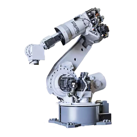
MOTOMAN-ES165D
INSTRUCTIONS
TYPE:
YR-ES0165D-A00 (STANDARD SPECIFICATION)
YR-ES0165D-A01 (SLU-AXES WITH LIMIT SWITCHES)
Upon receipt of the product and prior to initial operation, read these instructions thoroughly, and retain
for future reference.
MOTOMAN INSTRUCTIONS
MOTOVAN-ES165D INSTRUCTIONS
DX100 INSTRUCTIONS
DX100 OPERATOR'S MANUAL
DX100 MAINTENANCE MANUAL
The DX100 operator's manual above corresponds to specific usage.
Be sure to use the appropriate manual.
Part Number:
155976-1CD
Revision:
6
MANUAL NO.
HW0485249
1 of 92
9
Advertisement
Table of Contents

Subscribe to Our Youtube Channel
Related Manuals for YASKAWA MOTOMAN-ES165D


Summary of Contents for YASKAWA MOTOMAN-ES165D
- Page 1 MOTOMAN-ES165D INSTRUCTIONS TYPE: YR-ES0165D-A00 (STANDARD SPECIFICATION) YR-ES0165D-A01 (SLU-AXES WITH LIMIT SWITCHES) Upon receipt of the product and prior to initial operation, read these instructions thoroughly, and retain for future reference. MOTOMAN INSTRUCTIONS MOTOVAN-ES165D INSTRUCTIONS DX100 INSTRUCTIONS DX100 OPERATOR’S MANUAL DX100 MAINTENANCE MANUAL The DX100 operator’s manual above corresponds to specific usage.
- Page 2 Copyright © 2017, 2013 Yaskawa America, Inc. Terms of Use and Copyright Notice All rights reserved. This manual is freely available as a service to Yaskawa customers to assist in the operation of Motoman robots, related equipment and software This manual is copyrighted property of Yaskawa and may not be sold or redistributed in any way.
- Page 3 If such modification is made, the manual number will also be revised. • If your copy of the manual is damaged or lost, contact a YASKAWA representative to order a new copy. The representatives are listed on the back cover. Be sure to tell the representative the manual number listed on the front cover.
- Page 4 ALLOW UNTRAINED PERSONNEL TO OPERATE, PROGRAM, OR REPAIR THE EQUIPMENT! We recommend approved Yaskawa training courses for all personnel involved with the operation, programming, or repair of the equipment. This equipment has been tested and found to comply with the limits for a Class A digital device, pursuant to part 15 of the FCC rules.
- Page 5 Failure to observe this caution may result in electric shock or injury. • For disassembly or repair, contact your YASKAWA representative. • Do not remove the motor, and do not release the brake. Failure to observe these safety precautions may result in death or serious injury from unexpected turning of the manipulator's arm.
- Page 6 155976-1CD ES165D Notes for Safe Operation WARNING • Before operating the manipulator, check that servo power is turned OFF pressing the emergency stop buttons on the front door of the DX100 and the programming pendant. When the servo power is turned OFF, the SERVO ON LED on the programming pendant is turned OFF.
- Page 7 Read and understand the Explanation of Warning Labels in the DX100 Instructions before operating the manipulator: Definition of Terms Used In this Manual The MOTOMAN is the YASKAWA industrial robot product. The MOTOMAN usually consists of the manipulator, the controller, the programming pendant, and the manipulator cables.
- Page 8 Moving parts TYPE may cause PAYLOAD MASS injury DATE ORDER NO. SERIAL NO. WARNING Label B: YASKAWA ELECTRIC CORPORATION 2-1 Kurosakishiroishi, Yahatanishi-ku, WARNING Kitakyushu 806-0004 Japan MADE IN JAPAN NJ3878 Do not enter robot work area. viii 8 of 92...
- Page 9 155976-1CD ES165D Safeguarding Tips Safeguarding Tips All operators, programmers, maintenance personnel, supervisors, and anyone working near the system must become familiar with the operation of this equipment. All personnel involved with the operation of the equipment must understand potential dangers of operation. General safeguarding tips are as follows: •...
- Page 10 Do not make any modifications to the controller unit. Making any changes without the written permission from Yaskawa will void the warranty. • Some operations require standard passwords and some require special passwords.
- Page 11 Turn the power OFF and disconnect and lockout/tagout all electrical circuits before making any modifications or connections. Perform only the maintenance described in this manual. Maintenance other than specified in this manual should be performed only by Yaskawa- trained, qualified personnel. Summary of Warning Information This manual is provided to help users establish safe conditions for operating the equipment.
- Page 12 If you need assistance with any aspect of your ES165D system, please contact YASKAWA Customer Support at the following 24-hour telephone number: (937) 847-3200 For routine technical inquiries, you can also contact YASKAWA Customer Support at the following e-mail address: techsupport@motoman.com When using e-mail to contact YASKAWA Customer Support, please provide a detailed description of your issue, along with complete contact information.
-
Page 13: Table Of Contents
155976-1CD ES165D Table of Contents Table of Contents 1 Product Confirmation ........................1-1 1.1 Contents Confirmation ....................... 1-1 1.2 Order Number Confirmation ....................1-2 2 Transport............................2-1 2.1 Transport Method ......................2-1 2.1.1 Using a Crane ...................... 2-2 2.2 Shipping Bolts and Brackets....................2-3 3 Installation............................ - Page 14 155976-1CD ES165D Table of Contents 7 System Application.......................... 7-1 7.1 Peripheral Equipment Mounts.................... 7-1 7.2 Internal User I/O Wiring Harness and Air Line..............7-2 8 Electrical Equipment Specification ....................8-1 8.1 Position of Limit Switch ...................... 8-1 8.1.1 Specification of Limit Switch ................. 8-1 8.1.2 Location of Limit Switch ..................
- Page 15 155976-1CD ES165D Table of Contents 10 Recommended Spare Parts......................10-1 11 Parts List ............................. 11-1 11.1 S-Axis Unit ........................11-1 11.2 L-Axis Unit ........................11-3 11.3 URBT-Axes Unit ......................11-5 11.4 U-Arm Unit ........................11-8 11.5 Wrist Unit ........................11-10 11.6 Balancer Unit .......................
-
Page 16: Product Confirmation
155976-1CD ES165D Product Confirmation 1.1 Contents Confirmation Product Confirmation CAUTION • Confirm that the manipulator and the DX100 have the same order number. Special care must be taken when more than one manipulator is to be installed. If the numbers do not match, manipulators may not perform as expected and cause injury or damage. -
Page 17: Order Number Confirmation
155976-1CD ES165D Product Confirmation 1.2 Order Number Confirmation Order Number Confirmation Check that the order number of the manipulator corresponds to the DX100. The order number is located on a label as shown below. Fig. 1-1: Location of Order Number Labels Label (Enlarged View) THE MANIPULATOR AND THE CONTROLLER Check that the manipulator... -
Page 18: Transport
155976-1CD ES165D Transport 2.1 Transport Method Transport CAUTION • Sling applications and crane or forklift operations must be performed by authorized personnel only. Failure to observe this caution may result in injury or damage. • Avoid excessive vibration or shock during transport. The system consists of precision components. -
Page 19: Using A Crane
155976-1CD ES165D Transport 2.1 Transport Method 2.1.1 Using a Crane As a rule, the manipulator should be lifted by a crane with four wire ropes when removing it from the package and moving it. Be sure that the manipulator is fixed with the shipping bolts and brackets before transport, and lift it in the posture as shown in Fig. -
Page 20: Shipping Bolts And Brackets
155976-1CD ES165D Transport 2.2 Shipping Bolts and Brackets Shipping Bolts and Brackets The manipulator is provided with shipping bolts and brackets at position A and with the hexagon socket head cap screws at point B. (Fig. 2-1 “Transporting Position”). Fig. 2-2: Shipping Bolts and Brackets Shipping bracket Shipping bolt Hook... -
Page 21: Installation
155976-1CD ES165D Installation Installation WARNING • Install the safeguarding. Failure to observe this warning may result in injury or damage. • Install the manipulator in a location where the tool or the workpiece held by its fully extended arm will not reach the wall, safeguarding, or controller. -
Page 22: Safeguarding Installation
155976-1CD ES165D Installation 3.1 Safeguarding Installation Safeguarding Installation To insure safety, be sure to install safeguarding. It prevents unforeseen accidents with personnel and damage to equipment. Refer to the quoted clause for your information and guidance. Responsibility for Safeguarding (ISO10218) The user of a manipulator or robot system shall ensure that safeguards are provided and used in accordance with Sections 6, 7, and 8 of this standard. -
Page 23: Mounting Example
155976-1CD ES165D Installation 3.3 Location 3.2.1 Mounting Example For the first process, anchor the baseplate firmly to the ground. The baseplate should be rugged and durable to prevent shifting of the manipulator or the mounting fixture. It is recommend to prepare a baseplate of 50 mm or more thick, and anchor bolts of M20 or larger size. -
Page 24: Wiring
155976-1CD ES165D Wiring 4.1 Grounding Wiring WARNING • Ground resistance must be 100 Ω or less. Failure to observe this warning may result in fire or electric shock. • Before wiring, make sure to turn the primary power supply off, and put up a warning sign. -
Page 25: Cable Connection
155976-1CD ES165D Wiring 4.2 Cable Connection Cable Connection Three manipulator cables are delivered with the manipulator; an encoder cable for detection (1BC) and two power cables (2BC and 3BC). (Refer to Fig. 4-2 “Manipulator Cables”.) Connect these cables to the manipulator base connectors and to the DX100. - Page 26 155976-1CD ES165D Wiring 4.2 Cable Connection Fig. 4-2: Manipulator Cables The DX100 Side The Manipulator Side Encoder Cable The DX100 Side The Manipulator Side Power Cable The DX100 Side The Manipulator Side Power Cable 26 of 92 HW0485249...
- Page 27 155976-1CD ES165D Wiring 4.2 Cable Connection Fig. 4-3(a): Manipulator Cable Connectors (Manipulator Side) molex molex molex Key positions Connector Details (Manipulator Side) Fig. 4-3(b): Manipulator Cable Connection (DX100 Side) 27 of 92 HW0485249...
-
Page 28: Basic Specifications
155976-1CD ES165D Basic Specifications 5.1 Basic Specifications Basic Specifications Basic Specifications Table 5-1: Basic Specifications Item Model MOTOMAN-ES165D MOTOMAN-ES165D with external cabling for SRBT-axes Structure Vertically Articulated Degree of Freedom Payload 165 kg Repeatability ±0.2 mm Range of Motion S-Axis (turning) -180°... -
Page 29: Part Names And Working Axes
155976-1CD ES165D Basic Specifications 5.2 Part Names and Working Axes Part Names and Working Axes Fig. 5-1: Part Names and Working Axes Manipulator Base Dimensions Fig. 5-2: Manipulator Base Dimensions +0.021 Fitting surface 290 0.1 290 0.1 dia. (2 holes) (Pin hole for manipulator positioning) Fitting surface... -
Page 30: Dimensions And P-Point Maximum Envelope
155976-1CD ES165D Basic Specifications 5.4 Dimensions and P-Point Maximum Envelope Dimensions and P-Point Maximum Envelope Fig. 5-3: Dimensions and P-Point Maximum Envelope View A 4612 1961 2651 3050 P-point maximum envelope 1225 P-point 1024 Note: This figure shows the standard specification manipulator in the home position. 30 of 92 HW0485249... -
Page 31: Alterable Operating Range
Alterable Operating Range The operating range of the S-axis can be altered in accordance with the operating conditions as shown in Table 5-2 "S-Axis Operating Range". If alteration is necessary, contact your YASKAWA representative in advance. Table 5-2: S-Axis Operating Range... -
Page 32: Components For Altering Operating Range
155976-1CD ES165D Basic Specifications 5.5 Alterable Operating Range 5.5.1 Components for Altering Operating Range Arrange the components listed in Fig. 5-4 “The Components of the S-Axis Stopper”, when modifying the angle of S-axis. (1) Pin (drawing No. HW0402104-1, 1 pin) (2) Stopper (drawing No. -
Page 33: Notes On The Mechanical Stopper Installation
155976-1CD ES165D Basic Specifications 5.5 Alterable Operating Range 5.5.2 Notes on the Mechanical Stopper Installation • For S-Axis mechanical stopper, install the stopper (drawing No. HW0302424-2) with the pin which is used bottom up (drawing No. HW0402104-1) as in Fig. 5-4 “The Components of the S-Axis Stopper”. -
Page 34: Adjustment To The Pulse Limitation Of S-Axis
155976-1CD ES165D Basic Specifications 5.5 Alterable Operating Range 5.5.3 Adjustment to the Pulse Limitation of S-Axis To limit the operating range of the S-axis, refer to DX100 Instructions section 8.17 “Changing the Parameter Setting (162536-1CD)” and change the following parameters with the programming pendant. The limitation to the pulse (Pulse Soft Limit + 1st Axis ) : SICxG400 The limitation to the pulse (Pulse Soft Limit - 1st Axis ) : SICxG408 ±0°... - Page 35 155976-1CD ES165D Basic Specifications 5.5 Alterable Operating Range Table 5-3: The settable angle for S-Axis Stopper 35 of 92 HW0485249...
- Page 36 155976-1CD ES165D Basic Specifications 5.5 Alterable Operating Range Fig. 5-6(a): The Properly-Mounted Models for S-Axis Stopper Hexagon head screws The stopper is reversible. Either side of the stopper can be used. Installation at + 180° Hexagon head screws The stopper is reversible. Either side of the stopper can be used.
- Page 37 155976-1CD ES165D Basic Specifications 5.5 Alterable Operating Range Fig. 5-6(b): The Properly-Mounted Models for S-Axis Stopper The stopper is irreversible. Only this side of the stopper can be used at this angle. Hexagon head screws Installation at + 150° The stopper is reversible. Either side of the stopper can be used.
- Page 38 155976-1CD ES165D Basic Specifications 5.5 Alterable Operating Range Fig. 5-6(c): The Properly-Mounted Models for S-Axis Stopper The stopper is irreversible. Only this side of the stopper can be used at this angle. Hexagon head screws Installation at + 120° The stopper is reversible. Hexagon head screws Either side of the stopper can be used.
- Page 39 155976-1CD ES165D Basic Specifications 5.5 Alterable Operating Range Fig. 5-6(d): The Properly-Mounted Models for S-Axis Stopper The stopper is reversible. Either side of the stopper can be used. Hexagon head screws Installation at + 90° The stopper is reversible. Either side of the stopper can be used. Hexagon head screws Installation at + 75°...
- Page 40 155976-1CD ES165D Basic Specifications 5.5 Alterable Operating Range Fig. 5-6(e): The Properly-Mounted Models for S-Axis Stopper The stopper is irreversible. Only this side of the stopper can be used at this angle. Hexagon head screws Installation at + 60° The stopper is reversible. Either side of the stopper can be used.
- Page 41 155976-1CD ES165D Basic Specifications 5.5 Alterable Operating Range Fig. 5-6(f): The Properly-Mounted Models for S-Axis Stopper The stopper is irreversible. Only this side of the stopper can be used at this angle. Hexagon head screws Installation at + 30° The stopper is reversible. Either side of the stopper can be used.
-
Page 42: Allowable Load For Wrist Axis And Wrist Flange
If force is applied to the wrist instead of the load, force on R-, B-, and T-axes should be within the value shown in Table 6-1 "Allowable Wrist Load". Contact your YASKAWA representative for further information or assistance. Table 6-1: Allowable Wrist Load Axis Moment N•m (kgf•m) - Page 43 155976-1CD ES165D Allowable Load for Wrist Axis and Wrist Flange 6.1 Allowable Wrist Load Fig. 6-1: Moment Arm Rating LT(mm) 40kg 1000 60kg 80kg P-point 165kg T-, R-axis 130kg center of rotation 100kg 1400 1000 1200 LB(mm) 1000 LT(mm) B-axis center of rotation 43 of 92 HW0485249...
-
Page 44: Wrist Flange
155976-1CD ES165D Allowable Load for Wrist Axis and Wrist Flange 6.2 Wrist Flange Wrist Flange The wrist flange dimensions are shown in Fig. 6-2 “Wrist Flange”. It is recommended that the attachment be mounted inside the fitting in order to identify the alignment marks. -
Page 45: System Application
155976-1CD ES165D System Application 7.1 Peripheral Equipment Mounts System Application Peripheral Equipment Mounts The peripheral equipment mounts are provided on the U-axis (upper arm) and S-axis (rotary head) as shown in Fig. 7-1 “Installing Peripheral Equipment” for easier installation of the user's system applications. The following conditions shall be observed to attach or install peripheral equipment. -
Page 46: Internal User I/O Wiring Harness And Air Line
155976-1CD ES165D System Application 7.2 Internal User I/O Wiring Harness and Air Line Internal User I/O Wiring Harness and Air Line 6 cables for valves (0.75 mm ), 18 internal user I/O wires (0.5 mm 6 wires, 0.75 mm x 12 wires), the cables for the external axis (1.25 mm x 7 cables, 0.75 mm x 2 cables, 0.2 mm x 4 cables), and an air line are... - Page 47 155976-1CD ES165D System Application 7.2 Internal User I/O Wiring Harness and Air Line Fig. 7-2: Connectors for Internal User I/O Wiring Harness and Air Line Exhaust port (air flow) Tapped holes PT3/8 Connector for the external axis (Encoder cable): with pipe plug JL05-2A20-29SC (socket connector with cap).
- Page 48 155976-1CD ES165D System Application 7.2 Internal User I/O Wiring Harness and Air Line Fig. 7-3: Details of the Connector Pin Numbers 0.5mm (6 pins) 0.5mm (6 pins) 0.3mm (12 pins) Pins used Pins used 0.3mm (12 pins) 0.75mm (6 pins) 17 18 Pin details for internal user I/O wiring harness (Casing side)
-
Page 49: Electrical Equipment Specification
In case of re-adjusting the operating range of each subject axis, it is also required to change the dog location and limit NOTE values in software. Contact your YASKAWA representative if re-adjustment is required. 8.1.2 Location of Limit Switch The limit switch is optional. For the S-, L-, and U-axes with limit switch specifications, the limit switch is located on S-, L-, and U-axis respectively. -
Page 50: Setting Of Operation Range
155976-1CD ES165D Electrical Equipment Specification 8.1 Position of Limit Switch 8.1.3 Setting of Operation Range 8.1.3.1 S-Axis Operation Range By the S-axis limit switch, S-axis operation range can be set to those ranges mentioned in Table 5-2 "S-Axis Operating Range". 8.1.3.2 L-Axis Operation Range By the L-axis limit switch, the L-axis operation range can be set to any angles within -61°... -
Page 51: Setting Range Of Lu-Axes Interference Angle
155976-1CD ES165D Electrical Equipment Specification 8.1 Position of Limit Switch 8.1.3.3 Setting Range of LU-Axes Interference Angle L- and U-axes interference limit switches are designed to check the interference angle of L- and U-axes. As shown in Fig. 8-3 “LU-Axes Interference Angle”, the operation range of U-axis can be set to any angles within -8°... -
Page 52: Internal Connections
155976-1CD ES165D Electrical Equipment Specification 8.2 Internal Connections Internal Connections Highly reliable connectors are equipped on each connection part of the manipulator to enable easy removal and installation for maintenance and inspection. For the number and location of connectors, see Fig. 8-4 “Locations and Numbers of Connectors”. - Page 53 155976-1CD ES165D 8 Electrical Equipment Specification 8.2 Internal Connections Fig. 8-5(a): Internal Connection Diagram Notes 1. For the limit switch specification, the connection of the section 0BAT11 0BAT1 BAT11 BAT1 parts are changed as follows: 0BAT12 0BAT2 BAT12 BAT2 0BAT3 BAT3 S-AXIS OVERRUN L.S.
- Page 54 155976-1CD ES165D 8 Electrical Equipment Specification 8.2 Internal Connections Fig. 8-5(b): Internal Connection Diagram 2BC(8PX5+12PX1) S-AXIS OVERRUN L.S. Connected to CN1-1 CN1-1 CN1-2 CN1-2 CN1-3 CN1-3 L-AXIS OVERRUN L.S. Connected to CN1-5 CN1-5 CN1-6 CN1-6 CN1-7 CN1-7 No.9CN S-AXIS OVERRUN L.S. Connected to 9CN-A CN2-1...
-
Page 55: Maintenance And Inspection
Failure to observe this caution may result in electric shock or injury. • For disassembly or repair, contact your YASKAWA representative. • Do not remove the motor, and do not release the brake. Failure to observe these safety precautions may result in death or serious injury from unexpected turning of the manipulator's arm. - Page 56 Table 9-1: Inspection Items (Sheet 1 of 2) Items Schedule Method Operation Inspection Charge • • • • Alignment mark Visual Check alignment mark accordance at the home position. Check for damage. • • • • External lead Visual Check for damage and deterioration of leads. •...
- Page 57 17 Overhaul 1 Inspection No. correspond to the numbers in Fig. 9-1 “Inspection Items”. 2 The occurrence of a grease leakage indicates the possibility that grease has seeped into the motor. This can cause a motor breakdown. Contact your YASKAWA representative.
- Page 58 Fig. 9-1: Inspection Items R-AXIS B-AXIS T-AXIS S-AXIS 1 U-AXIS Check that no grease is leaked into the tube (2 tubes). L-AXIS 58 of 92...
- Page 59 155976-1CD ES165D Maintenance and Inspection 9.1 Inspection Schedule Table 9-2: Inspection Parts and Grease Used Grease Used Inspected Parts 12, 13, Molywhite RE No. 00 Speed Reducers for all Axes 14, 15, 16 R-, B-, and T-Axes gears Alvania EP Grease 2 L-Axis Balancer The numbers in the above table correspond to the numbers in Table 9-1 "Inspection Items"...
-
Page 60: Notes On Maintenance Procedures
155976-1CD ES165D Maintenance and Inspection 9.2 Notes on Maintenance Procedures Notes on Maintenance Procedures 9.2.1 Battery Pack Replacement The battery packs are installed in the position shown in Fig. 9-2(a) “Battery Location (Back View)” and Fig. 9-2(b) “Battery Location (Top View)”. If a battery alarm occurs in the DX100, replace the battery in accordance with the following procedure: Fig. - Page 61 155976-1CD ES165D Maintenance and Inspection 9.2 Notes on Maintenance Procedures Fig. 9-3: Battery Connection Battery pack See replacing step 5. before replacement Connector Board See replacing step 4. (Type : SGDR-EFBA02A) New battery pack 1. Turn OFF the DX100 main power supply. 2.
-
Page 62: Notes On Grease Replenishment/Exchange Procedures
155976-1CD ES165D Maintenance and Inspection 9.3 Notes on Grease Replenishment/Exchange Procedures Notes on Grease Replenishment/Exchange Procedures Make sure to follow the instructions listed below at grease replenishment/ exchange. Failure to observe the following notes may result in damage to motor and speed reducer. •... -
Page 63: Grease Replenishment
155976-1CD ES165D Maintenance and Inspection 9.3 Notes on Grease Replenishment/Exchange Procedures 9.3.1.1 Grease Replenishment (Refer to Fig. 9-4 “S-Axis Speed Reducer Diagram”.) Replenish the grease according to the following procedure: 1. Remove the hexagon socket head plugs PT3/8 from the grease exhaust port. -
Page 64: Grease Replenishment/Exchange For L-Axis Speed Reducer
155976-1CD ES165D Maintenance and Inspection 9.3 Notes on Grease Replenishment/Exchange Procedures 6. Wipe the discharged grease with a cloth, and reinstall the plug. Before installing the plug, apply Three Bond 1206C on the thread part of the plug, then tighten the plug with a tightening torque of 5 N•m (0.51 kgf•m). - Page 65 155976-1CD ES165D Maintenance and Inspection 9.3 Notes on Grease Replenishment/Exchange Procedures 9.3.2.2 Grease Exchange (Refer to Table 9-5 "L-Axis Speed Reducer Diagram".) 1. Make the L-arm vertical to the ground. 2. Remove the hexagon socket head plug PT3/8 from the grease exhaust port.
-
Page 66: Grease Replenishment/Exchange For U-Axis Speed Reducer
155976-1CD ES165D Maintenance and Inspection 9.3 Notes on Grease Replenishment/Exchange Procedures 9.3.3 Grease Replenishment/Exchange for U-Axis Speed Reducer Fig. 9-6: U-Axis Speed Reducer Diagram Grease exhaust port Hexagon socket head plug PT1/8 Grease inlet Hexagon socket head plug A-PT1/8 9.3.3.1 Grease Replenishment (Refer to Fig. -
Page 67: Grease Exchange
155976-1CD ES165D Maintenance and Inspection 9.3 Notes on Grease Replenishment/Exchange Procedures 9.3.3.2 Grease Exchange (Refer to Fig. 9-6 “U-Axis Speed Reducer Diagram”.) 1. Make the U-arm horizontal to the ground. 2. Remove the hexagon socket head plug PT1/8 from the grease exhaust port. -
Page 68: Grease Replenishment/Exchange For U-Arm
155976-1CD ES165D Maintenance and Inspection 9.3 Notes on Grease Replenishment/Exchange Procedures 9.3.4 Grease Replenishment/Exchange for U-Arm Fig. 9-7: U-Arm Diagram Grease inlet (R-,B-, and T-gears in the casing) Hexagon socket head plug A-PT1/8 T-axis speed reducer Grease exhaust port (T-axis speed reducer) Hexagon socket head plug PT1/16 R-axis speed reducer... -
Page 69: Grease Replenishment For R-Axis Speed Reducer
155976-1CD ES165D Maintenance and Inspection 9.3 Notes on Grease Replenishment/Exchange Procedures 3. Inject the grease through the grease inlet using a grease gun – Grease type: Molywhite RE No. 00 – Amount of grease: 300 cc (600 cc for 1st supply) –... -
Page 70: Grease Replenishment For B-Axis Speed Reducer
155976-1CD ES165D Maintenance and Inspection 9.3 Notes on Grease Replenishment/Exchange Procedures 9.3.4.3 Grease Replenishment for B-Axis Speed Reducer (Refer to Fig. 9-7 “U-Arm Diagram”.) 1. Remove the hexagon socket head plug PT1/8 from the grease exhaust port. If grease is injected with the plug on, the grease will leak NOTE inside the motor and may cause a damage. -
Page 71: Grease Exchange For R-, B-, T-Axes Gears In The Casing
155976-1CD ES165D Maintenance and Inspection 9.3 Notes on Grease Replenishment/Exchange Procedures 5. Wipe the discharged grease with a cloth, and reinstall the plug. Before installing the plug, apply Three Bond 1206C on the thread part of the plug, then tighten the plug with a tightening torque of 5 N•m (0.51 kgf•m). -
Page 72: Grease Exchange For B-Axis Speed Reducer
155976-1CD ES165D Maintenance and Inspection 9.3 Notes on Grease Replenishment/Exchange Procedures 3. Inject the grease through the grease inlet using a grease gun – Grease type: Molywhite RE No. 00 – Amount of grease: approx. 1550 cc – Air supply pressure of grease pump: 0.3 MPa or less –... -
Page 73: Grease Exchange For T-Axis Speed Reducer
155976-1CD ES165D Maintenance and Inspection 9.3 Notes on Grease Replenishment/Exchange Procedures 9.3.4.8 Grease Exchange for T-Axis Speed Reducer (Refer to Fig. 9-7 “U-Arm Diagram”.) 1. Remove the hexagon socket head plug PT1/8 from the grease exhaust port. If grease is injected with the plug on, the grease will leak NOTE inside the motor and may cause a damage. -
Page 74: Grease Replenishment For Balancer Connection Part
155976-1CD ES165D Maintenance and Inspection 9.3 Notes on Grease Replenishment/Exchange Procedures 9.3.5 Grease Replenishment for Balancer Connection Part Fig. 9-8: Balancer Connection Part Connection 2 Grease inlet Grease zerk A-PT1/8 Exhaust port 2 Hexagon socket head plug PT1/8 Exhaust port 1 Hexagon socket head plug PT1/8 Connection 2 Needle bearing Connection 1 Tapered roller bearing... -
Page 75: Notes For Maintenance
155976-1CD ES165D Maintenance and Inspection 9.3 Notes on Grease Replenishment/Exchange Procedures 9.3.6 Notes for Maintenance When performing maintenance such as replacement of a wire harness in the manipulator, the encoder connector may be necessary to be removed. In this case, be sure to connect the battery pack to the battery backup connector before removing the encoder connector. -
Page 76: Recommended Spare Parts
10 Recommended Spare Parts It is recommended to keep the parts and components in the following table in stock as spare parts for the MOTOMAN-ES165D. Product performance cannot be guaranteed when using spare parts from any company other than YASKAWA. The spare parts are ranked as follows: •... - Page 77 Recommended Spare Parts Table 10-1: Spare Parts for the YR-ES0165D-A00, -A01 (Sheet 2 of 2) Rank Parts Name Type Manufacturer Remarks Unit AC Servo Motor SGMRV-13ANA- YASKAWA for B-and T-Axes YR2* HW0388667-A Internal Wire HW0174287-A YASKAWA Harness Connector Base HW0374283-A...
-
Page 78: Parts List
155976-1CD ES165D Parts List 11.1 S-Axis Unit 11 Parts List 11.1 S-Axis Unit Fig. 11-1: S-Axis Unit 1037 1029 1038 1020 1030 1002 1004 1005 1035 1006 1036 1010 1008 1032 1031 1003 1011 1015 1025 1026 1001 1027 1016 1028 1021 1014... - Page 79 155976-1CD ES165D Parts List 11.1 S-Axis Unit Table 11-1: S-Axis Unit DWG No. Name 1001 HW0388208-A Speed reducer 1002 SGMRV-37ANA-YR1* Motor 1003 TC12015014 Oil seal 1004 STW-50 Retaining rings 1005 6310 Bearing 1006 HW0314016-1 Gear 1007 HW0100193-2 Base 1008 HW0100471-1 S head 1009 HW0402102-1...
-
Page 80: L-Axis Unit
155976-1CD ES165D Parts List 11.2 L-Axis Unit 11.2 L-Axis Unit Fig. 11-2: L-Axis Unit 2011 2040 2001 2039 2006 2042 2041 2046 2033 2037 2034 2019 2038 6004 2031 2020-26 2044 2032 2043 2012 2019 2005 2002 2017 2018 2019 2009 2010 2047... - Page 81 155976-1CD ES165D Parts List 11.2 L-Axis Unit Table 11-2: L-Axis Unit DWG No. Name 2001 HW9381442-B Speed reducer 2002 SGMRV-37ANA-YR1* Motor 2003 Y507212.5 Oil seal 2005 HR32916J Bearing 2006 HW0100472-1 L arm 2007 HW0303271-1 Gear 2009 HW9405055-1 Shaft 2010 EZ0094-A0 Air breather 2011 G300...
-
Page 82: Urbt-Axes Unit
155976-1CD ES165D Parts List 11.3 URBT-Axes Unit 11.3 URBT-Axes Unit Fig. 11-3: URBT-Axes Unit 3041 3042 3003 3039 3040 R-axis 3002 3007 3005 3041 3013 3042 3041 3018 3014 3042 B-axis 3050 3015 3050 3021 3027 3037 3004 3047 3045 3008 3020 3010... - Page 83 155976-1CD ES165D Parts List 11.3 URBT-Axes Unit Table 11-3: URBT-Axes Unit (Sheet 1 of 2) DWG No. Name 3001 HW0388209-A Speed reducer 3002 SGMRV-37ANA-YR1* Motor 3003 SGMRV-13ANA-YR1* Motor 3004 TAFI405520 Needle bearing 3005 Y507212.5 Oil seal 3006 Y507212.5 Oil seal 3007 HW0303963-1 Gear...
- Page 84 155976-1CD ES165D Parts List 11.3 URBT-Axes Unit Table 11-3: URBT-Axes Unit (Sheet 2 of 2) DWG No. Name 3046 2L-6 Spring washer 3047 HW9481343-A Shaft 3048 HW9482451-A Gear 3049 ISTW-12 Stopper 3050 SGMRV-13ANA-YR2* Motor 2006 HW0100472-1 L arm 4009 HW0100172-2 U arm 11-7 84 of 92...
-
Page 85: U-Arm Unit
155976-1CD ES165D Parts List 11.4 U-Arm Unit 11.4 U-Arm Unit Fig. 11-4: U-Arm Unit 4004 4008 4009 4028 4020 4019 4011 4003 4007 4026 4002 4015 4023 4022 3011 4021 4017 4005 4012 4018 4024 4025 4013 4024 4025 4006 4016 4006 4010... - Page 86 155976-1CD ES165D Parts List 11.4 U-Arm Unit Table 11-4: U-Arm Unit DWG No. Name 4001 NK25/20R Bearing 4002 HW1382917-A Speed reducer 4003 6810DDU Bearing 4004 HR32017XJ Bearing 4005 HR32013XJ Bearing 4006 HR32006XJ Bearing 4007 AC2847-F3-FKM Oil seal 4008 AC3842-F1-FKM Oil seal 4009 HW0100172-2 U arm...
-
Page 87: Wrist Unit
155976-1CD ES165D Parts List 11.5 Wrist Unit 11.5 Wrist Unit Fig. 11-5: Wrist Unit 4010 5089 5090 5023 5090 5041 5003 5024-28 5078 5022 5035 5045 5011 5012 5091 5073 5004 5048 5074 5014 5040 5088 5063-66 5046 5036 5047 5067 5098 5039... - Page 88 155976-1CD ES165D Parts List 11.5 Wrist Unit Table 11-5: Wrist Unit (Sheet 1 of 2) DWG No. Name 5001 HW9380961-D Speed reducer 5002 HW0389174-A Speed reducer 5002A FU00SC Fine U nut 5003 6908DB Bearing 5004 6909 Bearing 5005 6009 Bearing 5006 6907 Bearing...
- Page 89 155976-1CD ES165D Parts List 11.5 Wrist Unit Table 11-5: Wrist Unit (Sheet 2 of 2) DWG No. Name 5048 PT1/8 Plug 5049 PT1/16 Plug 5050 HW0406766-1 Shim 5051 HW0406766-2 Shim 5052 HW0406766-6 Shim 5053 HW0406766-7 Shim 5054 HW9403621-1 Shim 5055 HW9403621-2 Shim 5056...
-
Page 90: Balancer Unit
155976-1CD ES165D Parts List 11.6 Balancer Unit 11.6 Balancer Unit Fig. 11-6: Balancer Unit 6011 6004 6017 6005 6001 6007 6002 6006 6016 6015 6008 6012 6003 6003 6012 6014 6010 6013 2006 6009 2004 2014 2015 2016 2008 2013 2030 2029 11-13... - Page 91 155976-1CD ES165D Parts List 11.6 Balancer Unit Table 11-6: Balancer Unit DWG No. Name 6001 HW0481740-A Coil spring 6002 HW0481741-A Coil spring 6003 SOB607440 Oiless 6004 HW0100477-1 Case 6005 HW0306033-1 Flange 6006 HW0200420-1 Flange 6007 HW0401112-1 Flange 6008 HW0303581-1 6009 HW9405057-1 Clevis 6010...
- Page 92 INSTRUCTIONS HEAD OFFICE 2-1 Kurosakishiroishi, Yahatanishi-ku, Kitakyushu 806-0004, Japan Phone +81-93-645-7703 Fax +81-93-645-7802 YASKAWA America Inc. (Motoman Robotics Division) 100 Automation Way, Miamisburg, OH 45342, U.S.A. Phone +1-937-847-6200 Fax +1-937-847-6277 YASKAWA Europe GmbH Robotics Divsion ) Yaskawastrasse 1, 85391 Allershausen, Germany...
Need help?
Do you have a question about the MOTOMAN-ES165D and is the answer not in the manual?
Questions and answers