Table of Contents
Advertisement
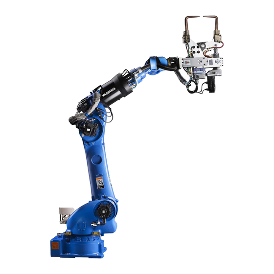
MOTOMAN-MS165
INSTRUCTIONS
TYPE:
YR-MS165/MH180-A00 (
Upon receipt of the product and prior to initial operation, read these instructions thoroughly, and
retain for future reference.
MOTOMAN INSTRUCTIONS
MOTOMAN-MS165 INSTRUCTIONS
DX200 INSTRUCTIONS
DX200 OPERATOR'S MANUAL (for each purpose)
The DX200 operator's manual above corresponds to specific usage. Be sure to use the appropriate manual.
STANDARD SPECIFICATION
Part Number:
Revision:
MANUAL NO.
HW1482308
)
167109-1CD
5
10
1 of 100
Advertisement
Table of Contents

Related Manuals for YASKAWA MOTOMAN-MS165


Summary of Contents for YASKAWA MOTOMAN-MS165
- Page 1 Upon receipt of the product and prior to initial operation, read these instructions thoroughly, and retain for future reference. MOTOMAN INSTRUCTIONS MOTOMAN-MS165 INSTRUCTIONS DX200 INSTRUCTIONS DX200 OPERATOR’S MANUAL (for each purpose) The DX200 operator’s manual above corresponds to specific usage. Be sure to use the appropriate manual.
- Page 2 Terms of Use and Copyright Notice All rights reserved. This manual is freely available as a service to Yaskawa customers to assist in the operation of Motoman robots, related equipment and software This manual is copyrighted property of Yaskawa and may not be sold or redistributed in any way. You are welcome to copy...
- Page 3 If such modification is made, the manual number will also be revised. • If your copy of the manual is damaged or lost, contact a YASKAWA representative to order a new copy. The representatives are listed on the back cover. Be sure to tell the representative the manual number listed on the front cover.
- Page 4 ALLOW UNTRAINED PERSONNEL TO OPERATE, PROGRAM, OR REPAIR THE EQUIPMENT! We recommend approved Yaskawa training courses for all personnel involved with the operation, programming, or repair of the equipment. This equipment has been tested and found to comply with the limits for a Class A digital device, pursuant to part 15 of the FCC rules.
- Page 5 Failure to observe this caution may result in electric shock or injury. • For disassembly or repair, contact your YASKAWA representative. • Do not remove the motor, and do not release the brake. Failure to observe these safety precautions may result in death or serious injury from unexpected turning of the manipulator's arm.
- Page 6 167109-1CD MS165 WARNING • Before operating the manipulator, check that servo power is turned OFF pressing the emergency stop buttons on the front door of the DX200 and the programming pendant. When the servo power is turned OFF, the SERVO ON LED on the programming pendant is turned OFF.
- Page 7 Read and understand the Explanation of Warning Labels in the DX200 Instructions before operating the manipulator. Definition of Terms Used Often in This Manual The MOTOMAN is the YASKAWA industrial robot product. The MOTOMAN usually consists of the manipulator, the controller, the programming pendant, and supply cables.
- Page 8 Also, an identification label with important information is placed on the body of the manipulator. Prior to operating the manipulator, confirm the contents. Note: Taking the maintenance-relevant trainings offered by YASKAWA is indispensable for replacing the L-axis of the balancer-equipped manipulator.
- Page 9 167109-1CD MS165 Safeguarding Tips All operators, programmers, maintenance personnel, supervisors, and anyone working near the system must become familiar with the operation of this equipment. All personnel involved with the operation of the equipment must understand potential dangers of operation. General safeguarding tips are as follows: •...
- Page 10 Do not make any modifications to the controller unit. Making any changes without the written permission from Yaskawa will void the warranty. • Some operations require a standard passwords and some require special passwords.
- Page 11 Turn the power OFF and disconnect and lockout/tagout all electrical circuits before making any modifications or connections. Perform only the maintenance described in this manual. Maintenance other than specified in this manual should be performed only by Yaskawa- trained, qualified personnel. Summary of Warning Information This manual is provided to help users establish safe conditions for operating the equipment.
- Page 12 If you need assistance with any aspect of your MS165 system, please contact Yaskawa Customer Support at the following 24-hour telephone number: (937) 847-3200 For routine technical inquiries, you can also contact Yaskawa Customer Support at the following e-mail address: techsupport@motoman.com When using e-mail to contact Yaskawa Customer Support, please provide a detailed description of your issue, along with complete contact information.
-
Page 13: Table Of Contents
167109-1CD MS165 Contents Table of Contents 1 Product Confirmation ........................1-1 1.1 Contents Confirmation ....................... 1-1 1.2 Order Number Confirmation ....................1-2 2 Transport............................2-1 2.1 Transport Method ......................2-2 2.1.1 Using a Crane....................... 2-2 2.2 Shipping Bolts and Brackets....................2-3 2.3 Cushioning Material for Transport .................. - Page 14 167109-1CD MS165 Contents 5.6 Alterable Operating Range ....................5-10 5.6.1 Components for Altering Operating Range............5-11 5.6.2 Notes on the Mechanical Stopper Installation ............ 5-12 5.6.3 Adjustment to the Pulse Limitation of S-Axis ............5-12 6 Allowable Load for Wrist Axis and Wrist Flange ................6-1 6.1 Allowable Wrist Load ......................
- Page 15 167109-1CD MS165 Contents 9.4.3 Gas Discharging Procedure ................9-19 9.4.3.1 Necessary Devices................9-19 9.4.3.2 Gas Discharging Procedures 9.4.4 Gas Injecting Procedure ..................9-22 9.4.4.1 Necessary Devices................9-22 9.4.4.2 Gas Injecting Procedures ..............9-22 9.5 Notes for Maintenance..................... 9-24 9.5.1 Battery Pack Connection ..................9-24 10 Recommended Spare Parts......................
-
Page 16: Product Confirmation
167109-1CD Product Confirmation MS165 1.1 Contents Confirmation Product Confirmation CAUTION • Confirm that the manipulator and the DX200 have the same order number. Special care must be taken when more than one manipulator is to be installed. If the numbers do not match, manipulators may not perform as expected and cause injury or damage. -
Page 17: Order Number Confirmation
167109-1CD Product Confirmation MS165 1.2 Order Number Confirmation Order Number Confirmation Check that the order number of the manipulator corresponds to the DX200. The order number is located on a label as shown below. Fig. 1-1: Location of Order Number Labels Label (Enlarged View) THE MANIPULATOR AND THE CONTROLLER Check that the manipulator... -
Page 18: Transport
167109-1CD Transport MS165 Transport CAUTION • Sling applications and crane or forklift operations must be performed by authorized personnel only. Failure to observe this caution may result in injury or damage. • Avoid excessive vibration or shock during transport. The system consists of precision components. Failure to observe this caution may adversely affect performances. -
Page 19: Transport Method
167109-1CD Transport MS165 2.1 Transport Method Transport Method • The weight of the manipulator is approximately 1070 kg including the shipping bolts and brackets. Use a wire rope strong enough to withstand the weight. • Shipping bolts and brackets are designed to support the manipulator weight. -
Page 20: Shipping Bolts And Brackets
167109-1CD Transport MS165 2.2 Shipping Bolts and Brackets Shipping Bolts and Brackets The manipulator is provided with shipping bolts and brackets. (fig. 2-2 “Shipping Bolts and Brackets” ). Fig. 2-2: Shipping Bolts and Brackets Hook 4xR20 Side view Front view •... -
Page 21: Installation
167109-1CD Installation MS165 Installation WARNING • Install the safeguarding. Failure to observe this warning may result in injury or damage. • Install the manipulator in a location where the tool or the workpiece held by its fully extended arm will not reach the wall, safeguarding, or controller. -
Page 22: Safeguarding Installation
167109-1CD Installation MS165 3.1 Safeguarding Installation Safeguarding Installation To insure safety, be sure to install safeguarding. It prevents unforeseen accidents with personnel and damage to equipment. Refer to the quoted clause for your information and guidance. Responsibility for Safeguarding (ISO10218) The user of a manipulator or robot system shall ensure that safeguards are provided and used in accordance with Sections 6, 7, and 8 of this standard. -
Page 23: Mounting Example
167109-1CD Installation MS165 3.2 Mounting Procedures for Manipulator Base Fig. 3-1: Manipulator Reaction Force and Torque 3.2.1 Mounting Example For the first process, anchor the baseplate firmly to the ground. The baseplate should be rugged and durable to prevent shifting of the manipulator or the mounting fixture. - Page 24 167109-1CD Installation MS165 3.2 Mounting Procedures for Manipulator Base Fig. 3-2: Mounting the Manipulator on Baseplate Hexagon socket head cap screw M20 (8 screws) Spring washer Washer Manipulator base Baseplate Flatness: 0.5mm or less Units: mm HW1482308 24 of 100...
-
Page 25: Location
167109-1CD Installation MS165 3.3 Location Location When installing a manipulator, it is necessary to satisfy the following environmental conditions: • Ambient temperature: 0 to + 45C • Humidity: 20 to 80%RH (no-condensing) • Free from dust, soot, oil, or water •... -
Page 26: Wiring
167109-1CD Wiring MS165 4.1 Grounding Wiring WARNING Ground resistance must be 100 or less. • Failure to observe this warning may result in fire or electric shock. • Before wiring, make sure to turn the primary power supply off, and put up a warning sign. -
Page 27: Cable Connection
167109-1CD Wiring MS165 4.2 Cable Connection Fig. 4-1: Grounding Method Bolt M8 (for grounding) 5.5mm or more Delivered with manipulator View A Cable Connection Two manipulator cables are delivered with the manipulator; an encoder cable for detection (1BC) and power cable (2BC). (Refer to fig. - Page 28 167109-1CD Wiring MS165 4.2 Cable Connection Fig. 4-2: Manipulator Cables The DX200 Side The Manipulator Side Encoder Cable The DX200 Side The Manipulator Side Power Cable HW1482308 28 of 100...
- Page 29 167109-1CD Wiring MS165 4.2 Cable Connection Fig. 4-3(a): Manipulator Cable Connectors (Manipulator Side) Key positions Key positions Connector Details (Manipulator Side) Fig. 4-3(b): Manipulator Cable Connection (DX200 Side) HW1482308 29 of 100...
-
Page 30: Basic Specifications
167109-1CD Basic Specifications MS165 5.1 Basic Specifications Basic Specifications Basic Specifications Table 5-1: Basic Specifications Item Model MOTOMAN-MS165 Flange for Cable Processing Not Equipped Equipped Application Spot Welding Structure Vertically Articulated Degree of Freedom Payload 180 kg 165 kg Repeatability ±0.2 mm... -
Page 31: Part Names And Working Axes
167109-1CD Basic Specifications MS165 5.2 Part Names and Working Axes Part Names and Working Axes Fig. 5-1: Part Names and Working Axes Manipulator Base Dimensions Fig. 5-2: Manipulator Base Dimensions +0.021 dia. (2 reamed holes) Fitting surface (Pin hole for manipulator positioning) ±0.1 ±0.1... -
Page 32: Dimensions And P-Point Maximum Envelope
167109-1CD Basic Specifications MS165 5.4 Dimensions and P-Point Maximum Envelope Dimensions and P-Point Maximum Envelope Fig. 5-3: Dimensions and P-Point Maximum Envelope Flange for cable processing View A 3673 2702 3061 P-point maximum envelope (290) 1225 P-point HW1482308 32 of 100... -
Page 33: Stopping Angles And Times For S-, L- And U-Axes
167109-1CD Basic Specifications MS165 5.5 Stopping Angles and Times for S-, L- and U-Axes Stopping Angles and Times for S-, L- and U-Axes Following data on stopping angle and time for each axis measured under the standard of ISO10218. 5.5.1 Stop Category 0: Stopping Angles and Times 5.5.1.1 Position 100% Fig. -
Page 34: Position 66%
167109-1CD Basic Specifications MS165 5.5 Stopping Angles and Times for S-, L- and U-Axes 5.5.1.2 Position 66% Fig. 5-5: Stop Category 0, Position 66% : Stopping Angle and Time for Each Axis (a)S-Axis Stop Category 0, Position 66% Stop Category 0, Position 66% (b)L-Axis Stop Category 0, Position 66% Stop Category 0, Position 66%... -
Page 35: Position 33%
167109-1CD Basic Specifications MS165 5.5 Stopping Angles and Times for S-, L- and U-Axes 5.5.1.3 Position 33% Fig. 5-6: Stop Category 0, Position 33% : Stopping Angle and Time for Each Axis (a)S-Axis Stop Category 0, Position 33% Stop Category 0, Position 33% (b)L-Axis Stop Category 0, Position 33% Stop Category 0, Position 33%... -
Page 36: Position100
167109-1CD Basic Specifications MS165 5.5 Stopping Angles and Times for S-, L- and U-Axes 5.5.2 Stop Category 1: Stopping Angles and Times Stopping angles and times at Stop category 1 are not NOTE subjected to the load of the manipulator. 5.5.2.1 Position100% Fig. -
Page 37: Position 66
167109-1CD Basic Specifications MS165 5.5 Stopping Angles and Times for S-, L- and U-Axes 5.5.2.2 Position 66% Fig. 5-8: Stop Category 1: Position 66% Stopping Angle and Time for Each Axis (a)S-Axis Stop Category 1, Position 66% Stop Category 1, Position 66% Note) Note depends on the load. -
Page 38: Position 33
167109-1CD Basic Specifications MS165 5.5 Stopping Angles and Times for S-, L- and U-Axes 5.5.2.3 Position 33% Fig. 5-9: Stop Category 1: Position 33% Stopping Angle and Time for Each Axis (a)S-Axis Stop Category 1, Position 33% Stop Category 1, Position 33% Note) Note depends on the load. -
Page 39: Alterable Operating Range
Alterable Operating Range The operating range of the S-axis can be altered in accordance with the operating conditions as shown in table 5-2 “S-Axis Operating Range” . If alteration is necessary, contact your YASKAWA representative in advance. Table 5-2: S-Axis Operating Range... -
Page 40: Notes On The Mechanical Stopper Installation
167109-1CD Basic Specifications MS165 5.6 Alterable Operating Range Fig. 5-10: The Components of the S-Axis Stopper Hexagon socket head cap screws M16 (4 screws)(length: 35) (tensile strength: 1200 N/mm or more) Conical spring washer 2H-16 (4 washers) Stopper HW1405450-1 Section A-A HW0402104-1 5.6.2 Notes on the Mechanical Stopper Installation For S-Axis mechanical stopper, install the stopper (drawing No. -
Page 41: Adjustment To The Pulse Limitation Of S-Axis
167109-1CD Basic Specifications MS165 5.6 Alterable Operating Range 5.6.3 Adjustment to the Pulse Limitation of S-Axis Apply the Instruction for “DX200 INSTRUCTIONS chapter 8.17 Changing the Parameter Setting (manual No. RE-CTO-A220)” as a part of reference materials for adjusting the programming pendant when modifying the range of motion of S-Axis. - Page 42 167109-1CD Basic Specifications MS165 5.6 Alterable Operating Range Table 5-3: The Settable Angle for S-Axis Stopper HW1482308 5-13 42 of 100...
- Page 43 167109-1CD Basic Specifications MS165 5.6 Alterable Operating Range Fig. 5-11(a): The Properly-Mounted Models for S-Axis Stopper Hexagon socket head cap screw fixing positions Installation at 180 Hexagon socket head cap screw fixing positions Installation at 165 HW1482308 5-14 43 of 100...
- Page 44 167109-1CD Basic Specifications MS165 5.6 Alterable Operating Range Fig. 5-11(b): The Properly-Mounted Models for S-Axis Stopper Hexagon socket head cap screw fixing positions Installation at 150 Hexagon socket head cap screw fixing positions Installation at 135 HW1482308 5-15 44 of 100...
- Page 45 167109-1CD Basic Specifications MS165 5.6 Alterable Operating Range Fig. 5-11(c): The Properly-Mounted Models for S-Axis Stopper Hexagon socket head cap screw fixing positions Installation at 120 Hexagon socket head cap screw fixing positions Installation at 105 HW1482308 5-16 45 of 100...
- Page 46 167109-1CD Basic Specifications MS165 5.6 Alterable Operating Range Fig. 5-11(d): The Properly-Mounted Models for S-Axis Stopper Hexagon socket head cap screw fixing positions Installation at 90 Hexagon socket head cap screw fixing positions Installation at 75 HW1482308 5-17 46 of 100...
- Page 47 167109-1CD Basic Specifications MS165 5.6 Alterable Operating Range Fig. 5-11(e): The Properly-Mounted Models for S-Axis Stopper Hexagon socket head cap screw fixing positions Installation at 60 Hexagon socket head cap screw fixing positions Installation at 45 HW1482308 5-18 47 of 100...
- Page 48 167109-1CD Basic Specifications MS165 5.6 Alterable Operating Range Fig. 5-11(f): The Properly-Mounted Models for S-Axis Stopper Hexagon socket head cap screw fixing positions Installation at 30 Hexagon socket head cap screw fixing positions Installation at 15 HW1482308 5-19 48 of 100...
- Page 49 167109-1CD Basic Specifications MS165 5.6 Alterable Operating Range Fig. 5-11(g): The Properly-Mounted Models for S-Axis Stopper Hexagon socket head cap screw fixing positions Installation at 0 HW1482308 5-20 49 of 100...
-
Page 50: Allowable Load For Wrist Axis And Wrist Flange
6-1(a) “Allowable Wrist Load (without flange for cable processing specification)” and fig. 6-1(b) “Allowable Wrist Load (with flange for cable processing specification)” . Contact your YASKAWA representative for further information or assistance. Table 6-1(a): Allowable Wrist Load (without flange for cable processing... - Page 51 167109-1CD Allowable Load for Wrist Axis and Wrist Flange MS165 6.1 Allowable Wrist Load Fig. 6-1: Moment Arm Rating Without flange for cable processing spec. LT(mm) 1200 40kg 1000 60kg 80kg 100kg 130kg 165kg P-point R-, T-axis 180kg center of rotation 400 600 800 10001200 1400 1600 LB(mm) 1000...
-
Page 52: Wrist Flange
167109-1CD Allowable Load for Wrist Axis and Wrist Flange MS165 6.2 Wrist Flange Wrist Flange The wrist flange dimensions are shown in fig. 6-2 “Wrist Flange” . In order to see the alignment mark, it is recommended that the attachment be mounted inside the fitting. -
Page 53: System Application
167109-1CD System Application MS165 7.1 Peripheral Equipment Mounts System Application Peripheral Equipment Mounts The peripheral equipment mounts are provided on the U-axis (upper arm) and S-axis (rotary head) as shown in fig. 7-1 “Installing Peripheral Equipment” for easier installation of the user’s system applications. The following conditions shall be observed to attach or install peripheral equipment. -
Page 54: Internal User I/O Wiring Harness And Air Line
167109-1CD System Application MS165 7.2 Internal User I/O Wiring Harness and Air Line Internal User I/O Wiring Harness and Air Line The internal user I/O wires (0.75 mm x 11 wires, 0.5 mm x 12 wires), the cables for the external axis (2.0 mm x 4 cables, 0.75 mm x 2 cables, 0.2 x 6 cables), and an air line are used in the manipulator for the drives... - Page 55 167109-1CD System Application MS165 7.2 Internal User I/O Wiring Harness and Air Line Fig. 7-3: Details of the Connector Pin Numbers Pins used 0.5mm 0.2mm (6 pins) (6 pins) Shielded wire 0.5mm (6 pins) 0.75mm Pin details for external axis encoder cable (11 pins) Pins used 2.0mm...
-
Page 56: Electrical Equipment Specification
In case of re-adjusting the operating range of each subject axis, it is also required to change the dog location and limit NOTE values in software. Contact your YASKAWA representative if re-adjustment is required. 8.1.2 Position of Limit Switch The limit switches are optional. For the S, L, and U-Axes with limit switches specifications, L.S. -
Page 57: Setting Of Operation Range
167109-1CD Electrical Equipment Specification MS165 8.1 Position of Limit Switch 8.1.3 Setting of Operation Range 8.1.3.1 S-Axis Operation Range By the S-axis limit switch, S-axis operation range can be set to those ranges mentioned in table 5-2 “S-Axis Operating Range” . 8.1.3.2 L-Axis Operation Range By the L-axis limit switch, the L-axis operation range can be set to any angles within -61°... - Page 58 167109-1CD Electrical Equipment Specification MS165 8.1 Position of Limit Switch Fig. 8-3: LU-Axes Interference Angle Positive side Negative side HW1482308 58 of 100...
-
Page 59: Internal Connections
167109-1CD Electrical Equipment Specification MS165 8.2 Internal Connections Internal Connections Highly reliable connectors are equipped on each connection part of the manipulator to enable easy removal and installation for maintenance and inspection. For the number and location of connectors, see fig. 8-4 “Locations and Numbers of Connectors”... - Page 60 167109-1CD MS165 8 Electrical Equipment Specification 8.1 Internal Connections Fig. 8-5(a): Internal Connection Diagram 0BAT11 0BAT1 Notes BAT11 BAT1 0BAT12 0BAT2 S-AXIS OVERRUN L.S. connected to A1 part BAT12 BAT2 0BAT3 For the limit switch specification, the connection of the section BAT3 L-AXIS OVERRUN L.S.
- Page 61 167109-1CD MS165 8 Electrical Equipment Specification 8.1 Internal Connections Fig. 8-5(b): Internal Connection Diagram 2BC(8PX3+12PX3) No.9CN 9CN-A S-AXIS B-10 B-10 No.10CN 10CN-A L-AXIS No.11CN 11CN-A U-AXIS No.12CN 12CN-A R-AXIS No.13CN C-11 13CN-A C-11 B-AXIS B-12 B-12 No.14CN 14CN-A T-AXIS B-11 B-11 No15CN(18-1) A-11...
-
Page 62: Maintenance And Inspection
Failure to observe this caution may result in electric shock or injury. • For disassembly or repair, contact your YASKAWA representative. • Do not remove the motor, and do not release the brake. Failure to observe these safety precautions may result in death or serious injury from unexpected turning of the manipulator's arm. - Page 63 Table 9-1: Inspection Items (Sheet 1 of 2) Items Schedule Method Operation Inspection Charge • • • • Alignment mark Visual Check alignment mark accordance at the home position. Check for damage. • • • • External lead Visual Check for damage and deterioration of leads. •...
- Page 64 1 Inspection No. correspond to the numbers in fig. 9-1 “Inspection Items” . 2 The occurrence of a grease leakage indicates the possibility that grease has seeped into the motor. This can cause a motor breakdown. Contact your YASKAWA representative.
- Page 65 Fig. 9-1: Inspection Items T-AXIS S-AXIS R-AXIS B-AXIS U-AXIS L-AXIS 65 of 100...
-
Page 66: Battery Pack Replacement
167109-1CD Maintenance and Inspection MS165 9.2 Battery Pack Replacement Battery Pack Replacement The battery packs are installed in the position shown in fig. 9-2(a) “Battery Location (Back View)” and fig. 9-2(b) “Battery Location (Top View)” . If a battery alarm occurs in the DX200, replace the battery in accordance with the following procedure: Fig. - Page 67 167109-1CD Maintenance and Inspection MS165 9.2 Battery Pack Replacement 1. Turn OFF the DX200 main power supply. 2. Remove the plate fixing screws and the plate on the connector base, then pull the battery pack out to replace it with the new one. 3.
-
Page 68: Grease Exchange
167109-1CD Maintenance and Inspection MS165 9.3 Grease Exchange Grease Exchange 9.3.1 Notes on Grease Exchange Procedures Make sure to follow the instructions listed below at grease exchange. Failure to observe the following notes may result in damage to motor and speed reducer. -
Page 69: List Of Necessary Items
167109-1CD Maintenance and Inspection MS165 9.3 Grease Exchange 9.3.2 List of Necessary Items Prepare necessary items as indicated in table 9-3 “List of Necessary Items” . “S”, “L”, “U”, “R”, and “BT” in the table mean axes for grease exchange to each axis, and “Casing” means R-, B-, and T-gear in a casing for grease exchange. -
Page 70: Grease Exchange
167109-1CD Maintenance and Inspection MS165 9.3 Grease Exchange Fig. 9-4: Recommended Posture of Each Axis While Injecting At filling grease to R,B,T-axis gear in the casing At filling grease to R-axis At filling grease to B, T-axis At filling grease to U-axis S-axis: Arbitrary S-axis: Arbitrary L-axis: Arbitrary... - Page 71 167109-1CD Maintenance and Inspection MS165 9.3 Grease Exchange Fig. 9-6: Plug Position of U-axis Speed Reducer and R-, B-, and T-gear in a casing R-, B-, T-gear inside the casing grease exhaust port Hexagon socket head plug PT3/8 U-axis grease exhaust port Hexagon socket head plug PT3/8 R-, B-, T-gear inside the casing grease inlet Hexagon socket head plug PT1/8...
- Page 72 167109-1CD Maintenance and Inspection MS165 9.3 Grease Exchange 2. Install the grease zerk to the grease inlet. (Refer to fig. 9-5 “Plug Position of S- and L-axis Speed Reducer” , fig. 9-6 “Plug Position of U-axis Speed Reducer and R-, B-, and T-gear in a casing” , and fig.
- Page 73 167109-1CD Maintenance and Inspection MS165 9.3 Grease Exchange Table 9-5: Amount of Grease Discharged from Each Axis Grease exchanging point Amount of exhausted grease [cc] S-axis 0 [Unnecessary] 0 [Unnecessary] L-axis 240±30 275±35 (240 to 310) U-axis 295±40 340±45 (295 to 385) R-, B-, T-gear in the casing 115±15 130±15 (115 to 145)
- Page 74 167109-1CD Maintenance and Inspection MS165 9.3 Grease Exchange Table 9-8: Plug Type and Tightening Torque of Each Axis Grease exchanging point Plug for grease inlet Plug for grease exhaust port Plug type Tightening torque Plug type Tightening torque S-axis PT1/4 12.0 N•m (1.2 kgf•m) L-axis PT3/8...
-
Page 75: Grease Replenishment For Gas Balancer Link Part
167109-1CD Maintenance and Inspection MS165 9.3 Grease Exchange 9.3.4 Grease Replenishment for Gas Balancer Link Part Fig. 9-9: Gas Balancer Link Part Link 2 Grease exhaust port (Hexagon socket head plug PT1/8) Link 2 Grease inlet (Hexagon socket head plug PT1/8) Link 2 Bearing Link 1 Bearing Link 1 Grease inlet... -
Page 76: Gas Maintenance Procedure In The Gas Balancer
• When handling high-pressure gas, sufficient caution and observing of the related laws and local government regulations are required. • For gas filling devices, contact your YASKAWA service representative. To maintain the sealing performance, small quantity of oil NOTE used may leak from the bottom part of the gas balancer. -
Page 77: Gas Pressure Inspection
167109-1CD Maintenance and Inspection MS165 9.4 Gas Maintenance Procedure in the Gas Balancer 9.4.2 Gas Pressure Inspection MANDATORY • Perform the gas pressure inspection every 6000H. • Operation of the manipulator with inadequate gas pressure gas balancer may cause failure or breakage. 9.4.2.1 Adequate Gas Pressure Adequate nitrogen gas pressure in the gas balancer varies depending on the temperature. -
Page 78: Necessary Device
167109-1CD Maintenance and Inspection MS165 9.4 Gas Maintenance Procedure in the Gas Balancer 9.4.2.2 Necessary Device Prepare following devices when checking the gas pressure. • Gas filling device: HW1485204 The device includes: Digital pressure gauge: GC64-173 Quick connector: 10-358-6297 • Thermometer (for measuring the gas balancer surface) 9.4.2.3 Inspection Procedures DANGER Before inspecting the gas pressure in the gas balancer or discharging/... -
Page 79: Gas Discharging Procedure
167109-1CD Maintenance and Inspection MS165 9.4 Gas Maintenance Procedure in the Gas Balancer 7. Remove the quick connector and mount the cover, then tighten the hexagon socket head screw plug M6 with flange by using a tightening torque of 4.9 N•m (0.5 kgf•m). 8. -
Page 80: Gas Discharging Procedures
167109-1CD Maintenance and Inspection MS165 9.4 Gas Maintenance Procedure in the Gas Balancer 9.4.3.2 Gas Discharging Procedures DANGER Before discharging/filling the gas from/into the gas balancer, confirm that the L-axis motor brake is appropriately functioning and L-axis is firmly fixed so that it will not rotate. Failure to observe this may cause very dangerous situation due to releasing of the L-axis motor brake. -
Page 81: Gas Injecting Procedure
167109-1CD Maintenance and Inspection MS165 9.4 Gas Maintenance Procedure in the Gas Balancer 6. Discharge gas by slowly releasing the blowdown valve until the gas pressure is the value shown in table 9-9 “Adequate Gas Pressure per Gas Balancer Surface Temperature” . After discharging/injecting gas, wait for a few minutes to NOTE stabilize the gas pressure, and then measure the gas pres-... -
Page 82: Gas Injecting Procedures
167109-1CD Maintenance and Inspection MS165 9.4 Gas Maintenance Procedure in the Gas Balancer 9.4.4.2 Gas Injecting Procedures DANGER Before discharging/filling the gas from/into the gas balancer, confirm that the L-axis motor brake is appropriately functioning and L-axis is firmly fixed so that it will not rotate. Failure to observe this may cause very dangerous situation due to releasing of the L-axis motor brake. - Page 83 167109-1CD Maintenance and Inspection MS165 9.4 Gas Maintenance Procedure in the Gas Balancer 14. Release the blowdown valve of the gas filling device and regulator, and then discharge the gas in the hose. 15. Disconnect the gas filling device from the nitrogen gas cylinder. 16.
-
Page 84: Notes For Maintenance
167109-1CD Maintenance and Inspection MS165 9.5 Notes for Maintenance Notes for Maintenance When performing maintenance such as replacement of a wire harness in the manipulator, the encoder connector may be necessary to be removed. In this case, be sure to con- nect the battery pack to the battery backup connector before removing the encoder connector. - Page 85 167109-1CD Maintenance and Inspection MS165 9.5 Notes for Maintenance Fig. 9-14: Battery Pack Connection Motor Motor power connector Connector for the encoder 0BT* BAT* Battery Pack: HW9470932-A Connector for the battery backup a:Insertion-type pin terminal (Pin) b:Insertion-type pin terminal (Socket) HW1482308 9-24 85 of 100...
-
Page 86: Recommended Spare Parts
10 Recommended Spare Parts It is recommended to keep the parts and components in the following table in stock as spare parts for the MOTOMAN-MS165. Product performance cannot be guaranteed when using spare parts from any company other than YASKAWA. The spare parts are ranked as follows: •... - Page 87 Table 10-1: Spare Parts for the YR-MS165/MH180-A00 (Sheet 2 of 2) Rank Part Name Type Manufacturer Remarks sNo. Unit Wrist Unit HW1171565-A YASKAWA Electric Corporation AC Servo Motor SGMRV-37ANA- YASKAWA Electric for S-, L-, and YR1* Corporation U-Axes HW0388670-A AC Servo Motor...
-
Page 88: Parts List
167109-1CD 11 Parts List MS165 11.1 S-Axis Unit 11 Parts List 11.1 S-Axis Unit Fig. 11-1: S-Axis Unit 1031 1032 1012 1002 1003 1018 1019 1027 1028 1046 1001 1004 1005 1013 1006 1016 1030 1024 1029 1025 1015 1045 1022 1023 1009... - Page 89 167109-1CD 11 Parts List MS165 11.1 S-Axis Unit Table 11-1: S-Axis Unit DWG No. Name 1001 HW0388208-B Speed reducer 1002 SGMRV-37ANA-YR1* Motor 1003 TC12015014 Oil seal 1004 STW-50 Retaining ring C-type 1005 6310 Bearing 1006 HW1303369-1 Gear 1007 HW1100520-1 Base 1008 HW1100521-1 S head...
-
Page 90: L-Axis Unit
167109-1CD 11 Parts List MS165 11.2 L-Axis Unit 11.2 L-Axis Unit Fig. 11-2: L-Axis Unit 2062 2078 2061 2053 2022 2007 2004 2016 2045 2028 2015 2011 2028 2010 2028 2046 2008 2079 2047 2078 2054 2009 2026 2001 2026 2025 2017 2025... - Page 91 167109-1CD 11 Parts List MS165 11.2 L-Axis Unit Table 11-2: L-Axis Unit (Sheet 1 of 2) DWG No. Name 2001 HW1382455-C Speed reducer 2002 SGMRV-37ANA-YR1* Motor 2003 HW9482447-A Oil seal 2004 HW1100591-1 L-arm 2005 HW1304057-1 Gear 2006 AS568-275 O ring 2007 VB75956 Oil seal...
- Page 92 167109-1CD 11 Parts List MS165 11.2 L-Axis Unit Table 11-2: L-Axis Unit (Sheet 2 of 2) DWG No. Name 2067 M4X6 Hexagon socket head cap screw 2068 2L-4 Conical spring washer 2069 HW1304369-A Cover 2070 M6X16 Hexagon socket head cap screw 2071 2L-6 Conical spring washer...
-
Page 93: Urbt-Axes Unit
167109-1CD 11 Parts List MS165 11.3 URBT-Axes Unit 11.3 URBT-Axes Unit Fig. 11-3: URBT-Axes Unit T-axis 3010 R-axis 3010 3027 3027 3007 3003 3011 3031 3011 3009 3029 3009 3029 3030 3001 3028 3008 3005 3008 3004 B-axis 3002 3010 3013 3014 3027... - Page 94 167109-1CD 11 Parts List MS165 11.3 URBT-Axes Unit Table 11-3: URBT-Axes Unit DWG No. Name 3001 HW0402391-1 Collar 3002 HW0402406-1 Collar 3003 HW1303889-1 Gear 3004 ISTW-36 Retaining ring 3005 HW0402390-1 Collar 3006 HW1303377-1 Gear 3007 HW1303378-1 Gear 3008 M6X25 Hexagon socket head cap screw 3009 2L-6 Conical spring washer...
-
Page 95: U-Arm Unit
167109-1CD 11 Parts List MS165 11.4 U-Arm Unit 11.4 U-Arm Unit Fig. 11-4: U-Arm Unit 3012 4024 4025 4021 4022 4002 4023 4019 4027 4035 4027 4016 4012 4008 4030 4018 4017 4006 4010 4007 4030 4014 4020 4011 4033 4013 4032 4031... - Page 96 167109-1CD 11 Parts List MS165 11.4 U-Arm Unit Table 11-4: U-Arm Unit DWG No. Name 4001 HW1100593-1 U-arm 4002 HW0401508-1 Plate 4003 6810DDU Bearing 4004 WR50 Retaining ring 4005 AC2847F3*NOK* Oil seal 4006 NK25/20R Needle bearing 4007 WR20 Circlip 4008 LRT202526 Bearing 4009...
-
Page 97: Wrist Unit
167109-1CD 11 Parts List MS165 11.5 Wrist Unit 11.5 Wrist Unit Fig. 11-5: Wrist Unit 4013 4012 5014 5013 5013 5009 5068 5012 5018 5010 5015 5037 5042 5011 5088 5025 5001 5073 5030 5026 5032 5023 5024 5028 5008 5061 5033 5038... - Page 98 167109-1CD 11 Parts List MS165 11.5 Wrist Unit Table 11-5: Wrist Unit (Sheet 1 of 2) DWG No. Name 5001 HW1100595-1 Wrist base 5002 M12X35 Hexagon socket head cap screw 5003 2H-12 Conical spring washer 5004 HW1100594-1 Wrist 5005 HW9380961-G Speed reducer 5006 M8X15...
- Page 99 167109-1CD 11 Parts List MS165 11.5 Wrist Unit Table 11-5: Wrist Unit (Sheet 2 of 2) DWG No. Name 5045 M14X40 Hexagon socket head cap screw 5046 GT-SH M14 Conical spring washer 5047 HW1303903-1 Flange 5050 HW0406766-* Shim 5057 HW9403621-* Shim 5061 HW9403622-*...
- Page 100 INSTRUCTIONS HEAD OFFICE 2-1 Kurosakishiroishi, Yahatanishi-ku, Kitakyushu 806-0004, Japan Phone +81-93-645-7703 Fax +81-93-645-7802 YASKAWA America Inc. (Motoman Robotics Division) 100 Automation Way, Miamisburg, OH 45342, U.S.A. Phone +1-937-847-6200 Fax +1-937-847-6277 YASKAWA Europe GmbH Robotics Divsion ) Yaskawastrasse 1, 85391 Allershausen, Germany...
Need help?
Do you have a question about the MOTOMAN-MS165 and is the answer not in the manual?
Questions and answers