Table of Contents
Advertisement
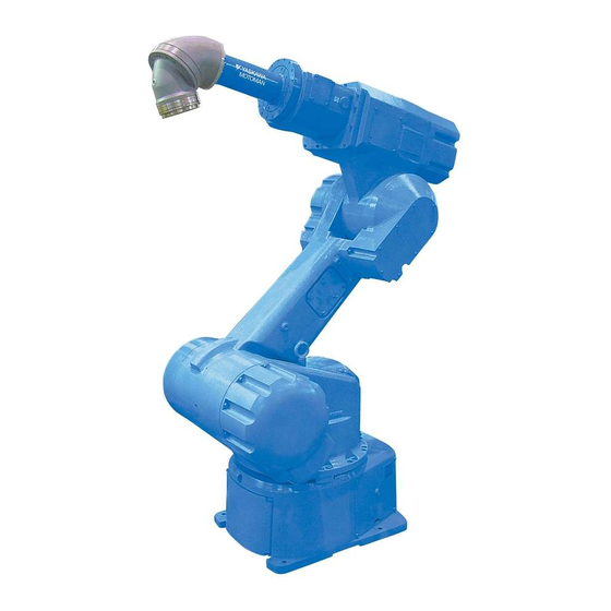
MOTOMAN-EPX1750 and EPX2050
INSTRUCTIONS
TYPE:
YR-EPX1750-B5**
YR-EPX2050-B5**
Upon receipt of the product and prior to initial operation, read these instructions thoroughly, and retain
for future reference.
MOTOMAN INSTRUCTIONS
MOTOMAN-EPX1750 & EPX2800 INSTRUCTIONS
NX100 INSTRUCTIONS
NX100 INSTRUCTIONS (EPX INSTRUCTION SUPPLEMENTS
NX100 OPERATOR'S MANUAL FOR PAINTING
NX100 MAINTENANCE MANUAL
The NX100 operator's manual above corresponds to specific usage.
Be sure to use the appropriate manual.
Part Number:
154771-1CD
Revision:
2
MANUAL NO.
HW0485080
1 of 66
2
Advertisement
Table of Contents

Related Manuals for YASKAWA MOTOMAN-EPX1750


Summary of Contents for YASKAWA MOTOMAN-EPX1750
- Page 1 YR-EPX2050-B5** Upon receipt of the product and prior to initial operation, read these instructions thoroughly, and retain for future reference. MOTOMAN INSTRUCTIONS MOTOMAN-EPX1750 & EPX2800 INSTRUCTIONS NX100 INSTRUCTIONS NX100 INSTRUCTIONS (EPX INSTRUCTION SUPPLEMENTS NX100 OPERATOR’S MANUAL FOR PAINTING NX100 MAINTENANCE MANUAL The NX100 operator’s manual above corresponds to specific usage.
- Page 2 Motoman robots, related equipment and software This manual is copyrighted property of Yaskawa and may not be sold or redistributed in any way. You are welcome to copy this document to your computer or mobile device for easy access but you may not copy the PDF files to another website, blog, cloud storage site or any other means of storing or distributing online content.
- Page 3 If such modification is made, the manual number will also be revised. • If your copy of the manual is damaged or lost, contact a YASKAWA representative to order a new copy. The representatives are listed on the back cover. Be sure to tell the representative the manual number listed on the front cover.
- Page 4 NEVER ALLOW UNTRAINED PERSONNEL TO OPERATE, PROGRAM, OR REPAIR THE EQUIPMENT! We recommend approved Yaskawa training courses for all personnel involved with the operation, programming, or repair of the equipment. This equipment has been tested and found to comply with the limits for a Class A digital device, pursuant to part 15 of the FCC rules.
- Page 5 154771-1CD Notes for Safe Operations Notes for Safe Operations Read this manual carefully before installation, operation, maintenance, or inspection of the MOTOMAN. In this manual, the Notes for Safe Operation are classified as “DANGER”, “WARNING”, “CAUTION”, “MANDATORY”, or “PROHIBITED”. Indicates an imminent hazardous situation which, if not DANGER avoided, could result in death or serious injury to personnel.
- Page 6 154771-1CD Notes for Safe Operations WARNING • Before operating the manipulator, check that servo power is turned OFF when the emergency stop buttons on the front door of the NX100 and programming pendant are pressed. When the servo power is turned OFF, the SERVO ON LED on the programming pendant is turned OFF.
- Page 7 154771-1CD Notes for Safe Operations CAUTION • Perform the following inspection procedures prior to conducting manipulator teaching. If problems are found, repair them immediately, and be sure that all other necessary processing has been performed. -Check for problems in manipulator movement. -Check for damage to insulation and sheathing of external wires.
- Page 8 154771-1CD Explanation of Warning Labels Explanation of Warning Labels The following warning labels are attached to the manipulator and NX100. Always follow the warnings on the labels. WARNING •The following warning labels are attached to NX100. Always follow the warnings on the labels. Neglect of this warning may cause a serious accident.
- Page 9 154771-1CD Definition of Terms Used Often in This Manual Definition of Terms Used Often in This Manual The MOTOMAN is the YASKAWA industrial robot product. The MOTOMAN usually consists of the manipulator, the controller, the programming pendant, and supply cables.
- Page 10 154771-1CD Customer Support Information Customer Support Information If you need assistance with any aspect of your EPX1750 & EPX2050 system, please contact Motoman Customer Support at the following 24-hour telephone number: (937) 847-3200 For routine technical inquiries, you can also contact Motoman Customer Support at the following e-mail address: techsupport@motoman.com When using e-mail to contact Motoman Customer Support, please provide a detailed description of...
-
Page 11: Table Of Contents
154771-1CD Table of Contents Table of Contents Safety Precautions Features 2.1 Methods of Protection ......2 2.2 Teaching . - Page 12 154771-1CD Table of Contents Connection 5.1 Wiring ..........5 5.1.1 Grounding .
- Page 13 154771-1CD Table of Contents Maintenance and Inspection 9.1 Inspection Schedule ....... 9 9.2 Maintenance for Manipulator .
- Page 14 WARNING Install the MOTOMAN-EPX1750 & EPX2050 in a location that meets the requirements of Area Classification “Division I” prescribed in FM Approval Standard.
- Page 15 Use the brake release function only when absolutely necessary. PROHIBITED Any modification of the MOTOMAN-EPX1750 & EPX2050, and the following is strictly prohibited: 1. Explosion-proof devices and system installation 2. Safeguards and the safety devices mounted on these safeguards 3.
-
Page 16: Features
Methods of Protection The MOTOMAN-EPX1750 & EPX2050 is evaluated as Type X Purged for use in Class Ι, Division 1, Groups A, B, C and D indoor hazardous (classified) Iocations T4, and appear in the Factory Mutual (FM) Research Approval Guide.They have the construction of protection as follows: Method of Protection;... -
Page 17: Teaching
154771-1CD 2 Features 2.2 Teaching Teaching The target positions, the motion speed, and the ON/OFF timing of the spray can be taught with the programming pendant while moving the manipulator, which shortens the time required for teaching and, the data can be corrected at any time. Because the teaching function and the correction function are integrated, the operations such as forward/reverse run, position modification, addition/deletion of points can be performed during teaching and the management function, which manages the parameter settings,... -
Page 18: Installation
154771-1CD 3 Installation 3.1 Requirements 3 Installation Requirements Prepare the power supply, the air supply, and the grounding according to the following specifications. Table 3-1 Specifications Item Specifications Remarks Power supply 3-phase 200/220 VAC (Option) (±10 % to -15 %) 3-phase 240/480/575VAC 50/60 Hz (±2 Hz) (+10% to -15%) -
Page 19: Installation Site
154771-1CD 3 Installation 3.2 Installation Site Installation Site This section describes the conditions of the installation site for the robot system. Only devices that are approved as explosion-proof can be installed in hazardous locations. Refer to the local regulations and safety codes for the definition of a hazardous location. Install the controller and control panels in a location free from water drops, dust, and dirt. -
Page 20: Transport And Installation
154771-1CD 4 Transport and Installation 4.1 Preparation 4 Transport and Installation Read the “Motoman Setup Manual” thoroughly before handling and installing the Motoman system, and then carry out the operation safely observing the following precautions. 1) Signs indicating prohibitions such as, “The lighting of fires is prohibited” 2) Clean working place that is clearly defined and free of obstacles 3) Appointment of personnel in charge 4) Company working regulations for safe operation... -
Page 21: Receiving And Handling
154771-1CD 4 Transport and Installation 4.2 Receiving and Handling Receiving and Handling When the package arrives, check the contents. Are the items and quantities in accordance with your order sheet? Was any damage incurred during shipment? CAUTION • Confirm that the manipulator and the NX100 have the same order number. Special care must be taken when more than one manipulator is to be installed. -
Page 22: Transport
154771-1CD 4 Transport and Installation 4.3 Transport Transport CAUTION • Sling and crane or forklift operations must be performed by authorized personnel only. Failure to observe this caution may result in injury or damage. • Avoid excessive vibration or shock during transport. The system consists of precision components. - Page 23 154771-1CD 4 Transport and Installation 4.3 Transport Using a Crane As a rule, when uncrating the manipulator and moving it, a crane should be used. Lift the manipulator with a wire rope using the attached eyebolts. Make sure to fix the manipulator with shipping bolts and brackets before transport, and lift it in the posture as shown in Fig.
-
Page 24: Shipping Bolts And Brackets
154771-1CD 4 Transport and Installation 4.3 Transport Using a Forklift When using a forklift, the manipulator should be fixed on a pallet with shipping bolts and bracket as shown in Fig. 4-3 "Transport Using a Forklift". Insert claws under the pallet and lift it. -
Page 25: Installation
154771-1CD 4 Transport and Installation 4.4 Installation Installation WARNING • Install the safeguarding. Failure to observe this warning may result in injury or damage. • Install the manipulator in a location where the manipulator’s tool or the workpiece held by the manipulator will not reach the wall, safeguarding, or NX100 when the arm is fully extended. -
Page 26: Installation Of Safeguarding
154771-1CD 4 Transport and Installation 4.4 Installation 4.4.1 Installation of Safeguarding To insure safety, be sure to install the safeguarding. They prevent unforeseen accidents with personnel and damage to equipment. The following is quoted for your information and guidance. Responsibility for Safeguarding (ISO 10218) The user of a manipulator or robot system shall ensure that safeguarding is provided and used in accordance with Sections 6, 7, and 8 of this standard. -
Page 27: Mounting The Manipulator On The Baseplate
154771-1CD 4 Transport and Installation 4.4 Installation 4.4.3 Mounting the Manipulator on the Baseplate The baseplate should be rugged and durable to withstand maximum repulsion force of the manipulator and to ensure that the manipulator and fixture are in the correct relative position. The thickness of the baseplate is 40 mm or more and an M16 size or larger anchor bolt is recommended. -
Page 28: Mounting Manipulator Directly On The Floor
154771-1CD 4 Transport and Installation 4.4 Installation 4.4.4 Mounting Manipulator Directly on the Floor The floor should be strong enough to support the manipulator. Construct a solid foundation with the appropriate thickness to withstand maximum repulsion forces of the manipulator. As a rough standard, when there is a concrete thickness (floor) of 150 mm or more, the manipulator base can be fixed directly on the floor with M16 anchor bolts. -
Page 29: Location
154771-1CD 4 Transport and Installation 4.4 Installation 4.4.5 Location When installing the manipulator, satisfy the following environmental conditions. • Ambient temperature: 0° to 40°C • Humidity: 20 to 80% RH at constant temperature • Free from exposure to water, oil, or dust •... -
Page 30: Connection
154771-1CD 5 Connection 5.1 Wiring 5 Connection Wiring WARNING • Ground resistance must be: - Non I.S. GND - 100 Ω or less - I.S. GND - 10 Ω or less Failure to observe this warning may result in fire or electric shock. •... -
Page 31: Grounding
154771-1CD 5 Connection 5.2 Cable Connection 5.1.1 Grounding The grounding methods differ depending on the system application. Refer to the connection instructions that are provided separately. Remove the Cover 5.5mm 2 or more (Prepare by the customer) less than 0.1W Fig. - Page 32 154771-1CD 5 Connection 5.2 Cable Connection Fig. 5-3 Manipulator Cable Connection 32 of 66 HW1480052...
-
Page 33: Power Cable Construction Method Example
154771-1CD 5 Connection 5.2 Cable Connection 5.2.2 Power Cable Construction Method Example The construction example is shown as follows: Fig. 5-4 Metal Pipe Construction Example • Construct the signal cable and the peripheral device coupling cable as mention above. • The metal pipe must have enough strength NOTE •... -
Page 34: Cable And Air Tube Connection
154771-1CD 5 Connection 5.3 Internal Connections 5.2.3 Cable and Air Tube Connection The cables and tubes necessary for installation are shown in the table below. The customer must prepare the power supply cable, the grounding cable, the cables for optional equipment, and the air tubes. Connection Type Power supply cable... - Page 35 Fig.5-5 (a) Internal Connection Diagram 35 of 66...
- Page 36 Fig.5-5 (b) Internal Connection Diagram 36 of 66...
-
Page 37: Internal Connections
154771-1CD 5 Connection 5.3 Internal Connections Fig.5-5 (c) Intrinsically Safe Circuit Diagram 37 of 66 HW1480052... -
Page 38: System Configuration
154771-1CD 6 System Configuration 6.1 Manipulator 6 System Configuration Fig. 6-1 "System Configuration" shows the system configuration of the MOTOMAN-EPX1750 & EPX2050. Manipulator The explosion-proof manipulator can be installed in hazardous locations such as in the painting booth. For painting, a spray gun is mounted on the end of the wrist with special fixtures. - Page 39 154771-1CD 6 System Configuration 6.1 Manipulator Fig. 6-1 System Configuration Fig. 6-2 Dimensions and P-point Maximum Envelope 39 of 66 HW1480052...
-
Page 40: Robot Controller
154771-1CD 6 System Configuration 6.2 Robot Controller Robot Controller The robot controller has a built-in microcomputer that controls all motion of the robot by saving motion signals when teaching and sending these signals to the manipulator. The power unit that supplies power to the manipulator is also built into the robot controller. DANGER •... - Page 41 154771-1CD 6 System Configuration 6.3 Pneumatic Unit Fig. 6-3 Pneumatic Unit Air Circuit CAUTION Manufacturer is requested to strictly, observe that the supply air is between 0.35 MPa to 0.65 MPa. The pressurized explosion-proof will not operate properly without the required amount of air pressure, if air pressure is low.
-
Page 42: O-Ring And X-Ring In The Wrist
6.4 O-Ring and X-Ring in the Wrist O-Ring and X-Ring in the Wrist Periodically replace the O-ring and X-ring in the wrist. Contact your Yaskawa representative to replace the ring. When the wrist is cleaned two or three times a week with the recovered thinner, the O-rings may become deformed, which causes malfunctions. -
Page 43: Basic Specifications
154771-1CD 7 Basic Specifications 7.1 Basic Specifications 7 Basic Specifications Basic Specifications Table 7-1 Basic Specifications Item Type EPX1750-B5** EPX2050-B5** Configuration Vertically articulated Degree of Freedom Payload 15 kg ± 0.5 mm Repeatability S-axis (turning) ± 90° L-axis (lower arm) +100°... -
Page 44: Wrist Flange
154771-1CD 7 Basic Specifications 7.2 Wrist Flange Wrist Flange The wrist flange dimensions are shown in Fig. 7-1 "Wrist Flange". Fitting depth of inside and outside fittings must be 7 mm or less. Fig. 7-1 Wrist Flange 44 of 66 HW1480052... -
Page 45: System Application
154771-1CD 7 Basic Specifications 7.3 System Application System Application The device required for the system application can be mounted on the horizontal arm. Observe the following restriction. • Maximum allowable load: 15 kg • Mounting Position: Refer to Fig. 7-2 "Device Mounting Position" Fig. -
Page 46: Frequent Inspections
154771-1CD 8 Frequent Inspections 8.1 Frequent Inspections 8 Frequent Inspections Frequent Inspections The painting robot is a precision device using advanced technology. It is important to frequently inspect the robot and remove any dried paint. Conduct the daily and weekly inspections listed in Table 8-1 "Frequent Inspections" to ensure the long life of the robot and its performance. - Page 47 154771-1CD 8 Frequent Inspections 8.1 Frequent Inspections Table 8-1 Frequent Inspections Items to be Inspected Inspection Daily Weekly Remarks Operation of emer- 1. The manipulator CAUTION gency stop button stops immediately and safety plug. when the Inspect the robot while Dried paint emergency stop it is in its standby posi-...
-
Page 48: Daily Inspections
154771-1CD 8 Frequent Inspections 8.2 Daily Inspections Daily Inspections Inspect the robot daily to ensure its high performance and early detection of any abnormalities. 8.2.1 Manipulator Visual Inspection Before turning ON the power to the manipulator, check if any abnormality can be found on the manipulator. -
Page 49: Pneumatic Unit
154771-1CD 8 Frequent Inspections 8.2 Daily Inspections Dried Paint, Dust, and Dirt Remove any dried paint on the manipulator and other devices. Replace the vinyl sheet if any. Replace the jacket if it is dirty. WARNING When using a tool to remove the dried paint, be careful not to damage the manipulator. ... -
Page 50: Options
154771-1CD 8 Frequent Inspections 8.2 Daily Inspections Photoelectric Intrusion Detecting Switch Make sure that the photoelectric intrusion detecting switch operates correctly. Remove any dried paint on the light beam receiving section on the switch. When the air is purging, check the air for purging. Limit Switch ... -
Page 51: Maintenance And Inspection
• Maintenance and inspection must be performed by specified personnel. Failure to observe this caution may result in electric shock or injury. • For disassembly or repair, contact your Yaskawa representative. • Do not remove the motor, and do not release the brake. -
Page 52: Inspection Schedule
Replace the belt and gear if any abnormality is found. Replenish Use Alvania EP grease 2 grease Gear inside the Contact your Yaskawa repre- wires Inspection, sentative for gear adjustment Adjustment replacement and gear grease... - Page 53 Grease in the motor may cause motor failure. When any grease enters in the motor, contact your Yaskawa representative. b.When checking for conduction with multimeter, connect the battery to “BAT” and “OBT” of connectors on the motor side for each axis, and then remove connectors on detector side for each axis from the motor.
-
Page 54: Maintenance For Manipulator
154771-1CD 9 Maintenance and Inspection 9.2 Maintenance for Manipulator Maintenance for Manipulator 9.2.1 Grease Replenishment/Replacement Inspection parts and Inspection numbers show the location of the components of the manipulator. Replenish or replace the grease for the following: 1) Gears on the wrist and the end of the U-arm 2) RV speed reducers for the S-, L- and U-axis ... - Page 55 154771-1CD 9 Maintenance and Inspection 9.2 Maintenance for Manipulator RV Speed Reducers Grease Replenishment Refer to Fig , Fig, and Fig Remove the cover on the 1. Remove the plug on the So (Lo, Uo) grease exhaust port. L-axis motor side. •...
- Page 56 154771-1CD 9 Maintenance and Inspection 9.2 Maintenance for Manipulator grease, remove the plugs on Li and Ui and install G nipples A-PT 1/8.) Grease type: Molywhite RE No.00 Amount of grease: S-axis: 1700 cc L-axis: 2000 cc U-axis: 900 cc 3.
-
Page 57: Lubricating Oil Replacement R-, B-, And T-Axis Speed Reducers
Lubricating Oil Replacement R-, B-, and T-Axis Speed Reducers Contact your Yaskawa representative because motors and drive shafts for the R- B-, and T-axis need to be removed to replace the lubricating oil.. • Recommend lubricating oil: Renolin PG220 made by Fuchs Lubricants Co. Viscosity =... -
Page 58: Tightening Bolts
154771-1CD 9 Maintenance and Inspection 9.2 Maintenance for Manipulator 9.2.3 Tightening Bolts Tighten the bolts shown in Fig. 9-6 "Manipulator Base Box Fixing Bolts" to Fig. 9-8 "Terminal Box in Manipulator Base Box" Fig. 9-6 Manipulator Base Box Fixing Bolts Fig. -
Page 59: Wrist Speed Reducer And Bearing
Check if the three wrist axis move smoothly or not. If the wrist does not move smoothly, contact your Yaskawa representative. Removing and disassembling the wrist to find the faulty axis will be needed for repair or replacement of the bearing, the speed reducer, or the sealing compounds. -
Page 60: Air Sealings For Internal Air Pressure
154771-1CD 9 Maintenance and Inspection 9.2 Maintenance for Manipulator 9.2.5 Air Sealings for Internal Air Pressure Packing on the Motor Case Remove the mounting bolts on the motor case and check the packing where the case is mounted. Remove the cover for the cable inlet in the motor case, and check the packing where the cover is attached. - Page 61 154771-1CD 9 Maintenance and Inspection 9.2 Maintenance for Manipulator Manipulator Base Box Cover Packing Remove the two covers on the back side of the manipulator base box, and check the rubber packing. Refer to Fig. 9-11 "Manipulator Base Box Rubber Packing" Fig.
-
Page 62: Maintenance And Inspection Of The Pneumatic Unit
154771-1CD 9 Maintenance and Inspection 9.3 Maintenance and Inspection of the Pneumatic Unit Maintenance and Inspection of the Pneumatic Unit 9.3.1 Solenoid Valve Check if the air purge starts a few seconds after turning ON the power to the NX100 and if it ends approximately 8.5 minutes later. -
Page 63: Inspection Of Explosion-Proof Devices
154771-1CD 9 Maintenance and Inspection 9.4 Inspection of Explosion-Proof Devices Inspection of Explosion-Proof Devices 9.4.1 Pressure Switch Remove the front cover of the pneumatic unit box and check the conduction of the pressure switches. The two pressure switches must be ON when the air is being supplied and OFF when the air is not being supplied. -
Page 64: Recommended Spare Parts
• Rank B: Parts for which replacement may be necessary as a result of frequent operation • Rank C: Drive units NOTE To replace parts in Rank B or Rank C, contact your Yaskawa representative. Fig. 10-1 Spare Parts for MOTOMAN-EPX1750 & EPX2050 Part... - Page 65 154771-1CD 10 Recommended Spare Parts Fig. 10-1 Spare Parts for MOTOMAN-EPX1750 & EPX2050 Part Rank Name Type Manufacturer Remarks Unit HW0370224-A EPX2050-B500, -B510 Switch unit Yaskawa HW0370224-B EPX2050-B501, -B511 Internal Cable HW0272857-A Yaskawa For S-axis Internal Cable HW0373190-A Yaskawa For L-axis motor...
- Page 66 INSTRUCTIONS HEAD OFFICE 2-1 Kurosakishiroishi, Yahatanishi-ku, Kitakyushu 806-0004, Japan Phone +81-93-645-7703 Fax +81-93-645-7802 YASKAWA America Inc. (Motoman Robotics Division) 100 Automation Way, Miamisburg, OH 45342, U.S.A. Phone +1-937-847-6200 Fax +1-937-847-6277 YASKAWA Europe GmbH Robotics Divsion ) Yaskawastrasse 1, 85391 Allershausen, Germany...
Need help?
Do you have a question about the MOTOMAN-EPX1750 and is the answer not in the manual?
Questions and answers