Table of Contents
Advertisement
MOTOMAN-MPL300 II
INSTRUCTIONS
TYPE:
YR-MPL0300-J00 (DX200 STANDARD SPECIFICATION)
Upon receipt of the product and prior to initial operation, read these instructions thoroughly, and
retain for future reference.
MOTOMAN INSTRUCTIONS
MOTOMAN-MPL300 II INSTRUCTIONS
DX200 INSTRUCTIONS
DX200 OPERATOR'S MANUAL (for each purpose)
DX200 MAINTENANCE MANUAL
The DX200 operator's manual above corresponds to specific usage. Be sure to use the appropriate manual.
Part Number:
173124-1CD
Revision:
2
MANUAL NO.
HW1482991
2
1 of 100
Advertisement
Table of Contents

Subscribe to Our Youtube Channel
Related Manuals for YASKAWA Motoman-MPL300 II


Summary of Contents for YASKAWA Motoman-MPL300 II
- Page 1 YR-MPL0300-J00 (DX200 STANDARD SPECIFICATION) Upon receipt of the product and prior to initial operation, read these instructions thoroughly, and retain for future reference. MOTOMAN INSTRUCTIONS MOTOMAN-MPL300 II INSTRUCTIONS DX200 INSTRUCTIONS DX200 OPERATOR’S MANUAL (for each purpose) DX200 MAINTENANCE MANUAL The DX200 operator’s manual above corresponds to specific usage. Be sure to use the appropriate manual.
- Page 2 Copyright © 2018, 2015, 2014 Yaskawa America, Inc. Terms of Use and Copyright Notice All rights reserved. This manual is freely available as a service to Yaskawa customers to assist in the operation of Motoman robots, related equipment and software This manual is copyrighted property of Yaskawa and may not be sold or redistributed in any way.
- Page 3 If such modification is made, the manual number will also be revised. • If your copy of the manual is damaged or lost, contact a YASKAWA representative to order a new copy. The representatives are listed on the back cover. Be sure to tell the representative the manual number listed on the front cover.
- Page 4 Failure to observe this caution may result in electric shock or injury. • For disassembly or repair, contact your YASKAWA representative. • Do not remove the motor, and do not release the brake. Failure to observe these safety precautions may result in death or serious injury from unexpected turning of the manipulator's arm.
- Page 5 173124-1CD Notes for Safe Operation MPL300 WARNING • Before operating the manipulator, check that servo power is turned OFF pressing the emergency stop buttons. When the servo power is turned OFF, the SERVO ON LED on the programming pendant is turned OFF. Injury or damage to machinery may result if the emergency stop circuit cannot stop the manipulator during an emergency.
- Page 6 Read and understand the Explanation of Warning Labels in the DX200 Instructions before operating the manipulator: Definition of Terms Used Often in This Manual The MOTOMAN is the YASKAWA industrial robot product. The MOTOMAN usually consists of the manipulator, the controller, the programming pendant, and supply cables.
- Page 7 Also, an identification label with important information is placed on the body of the manipulator. Prior to operating the manipulator, confirm the contents. Note: Taking the maintenance-relevant trainings offered by YASKAWA is indispensable for replacing the L-axis of the balancer-equipped manipulator.
- Page 8 173124-1CD Signal Output for Motor Protection MPL300 Signal Output for Motor Protection A cooling fan is equipped in order to protect the motor of S-axis of the manipulator from overheating. If the cooling fan is aut of ordet, warning message [COOLING FAN2 ERROR] will appear on the programming pendant.
- Page 9 173124-1CD Mechanical Safety Devices MPL300 Mechanical Safety Devices The safe operation of this equipment is ultimately the users responsibility. The conditions under which the equipment will be operated safely should be reviewed by the user. The user must be aware of the various national codes, ANSI/RIA R15.06-2012 safety standards, and other local codes that may pertain to the installation and use of this equipment.
- Page 10 Do not make any modifications to the controller unit. Making any changes without the written permission from Yaskawa will void the warranty. • Some operations require a standard passwords and some require special passwords.
- Page 11 Turn the power OFF and disconnect and lockout/tagout all electrical circuits before making any modifications or connections. Perform only the maintenance described in this manual. Maintenance other than specified in this manual should be performed only by Yaskawa- trained, qualified personnel. Summary of Warning Information This manual is provided to help users establish safe conditions for operating the equipment.
- Page 12 173124-1CD Customer Support Information MPL300 Customer Support Information If you need assistance with any aspect of your MPL300 system, please contact Customer Support at the following 24-hour telephone number: (937) 847-3200 For routine technical inquiries, you can also contact Customer Support at the following e-mail address: techsupport@motoman.com When using e-mail to contact Customer Support, please provide a...
-
Page 13: Table Of Contents
173124-1CD Table of Contents MPL300 Table of Contents 1 Product Confirmation ........................1-1 1.1 Contents Confirmation ....................... 1-1 1.2 Order Number Confirmation ....................1-2 2 Transport............................2-1 2.1 Transport Method ......................2-1 2.1.1 Using a Crane ...................... 2-2 2.2 Shipping Bolts and Brackets....................2-3 3 Installation............................ - Page 14 173124-1CD Table of Contents MPL300 5.6 Alterable Operating Range ....................5-7 5.6.1 Components for Altering Operating Range............5-8 5.6.2 Notes on the Mechanical Stopper Installation ............5-9 5.6.3 Adjustment of the Soft Limit of the S-Axis Pulse ..........5-10 6 Allowable Load for Wrist Axis and Wrist Flange ................6-1 6.1 Allowable Wrist Load ......................
- Page 15 173124-1CD Table of Contents MPL300 9.3.8 Notes for Maintenance ..................9-20 9.3.8.1 Battery Pack Connection............... 9-20 10 Recommended Spare Parts......................10-1 11 Parts List ............................. 11-1 11.1 S-Axis Unit ........................11-1 11.2 L-Axis Unit ........................11-4 11.3 U-Axis Unit........................11-8 11.4 Wrist Unit ........................
-
Page 16: Product Confirmation
173124-1CD Product Confirmation MPL300 1.1 Contents Confirmation Product Confirmation CAUTION • Confirm that the manipulator and the DX200 have the same order number. Special care must be taken when more than one manipulator is to be installed. If the numbers do not match, manipulators may not perform as expected and cause injury or damage. -
Page 17: Order Number Confirmation
173124-1CD Product Confirmation MPL300 1.2 Order Number Confirmation Order Number Confirmation Check that the order number of the manipulator corresponds to the DX200. The order number is located on a label as shown below. Fig. 1-1: Location of Order Number Labels Label (Enlarged View) THE MANIPULATOR AND THE CONTROLLER Check that the manipulator... -
Page 18: Transport
173124-1CD Transport MPL300 2.1 Transport Method Transport CAUTION • Sling applications and crane or forklift operations must be performed by authorized personnel only. Failure to observe this caution may result in injury or damage. • Avoid excessive vibration or shock during transport. The system consists of precision components. -
Page 19: Using A Crane
173124-1CD Transport MPL300 2.1 Transport Method 2.1.1 Using a Crane As a rule, the manipulator should be lifted by a crane with four wire ropes when removing it from the package and moving it. Be sure that the manipulator is fixed with the shipping bolts and brackets before transport, and lift it in the posture as shown in Fig. -
Page 20: Shipping Bolts And Brackets
173124-1CD Transport MPL300 2.2 Shipping Bolts and Brackets Shipping Bolts and Brackets The manipulator is provided with shipping bolts and brackets at positions A, B, and C. (See Fig. 2-1 “Transporting Position”.) • The shipping bolts and brackets are painted yellow. Position Screw Type Hexagon socket head cap screw M20... -
Page 21: Installation
173124-1CD Installation MPL300 3.1 Installation of Safeguarding Installation WARNING • Install the safeguarding. Failure to observe this warning may result in injury or damage. • Install the manipulator in a location where the tool or the workpiece held by its fully extended arm will not reach the wall, safeguarding, or controller. -
Page 22: Mounting Procedures For Manipulator Base
173124-1CD Installation MPL300 3.2 Mounting Procedures for Manipulator Base Mounting Procedures for Manipulator Base The manipulator should be firmly mounted on a baseplate or foundation strong enough to support the manipulator and withstand repulsion forces during acceleration and deceleration. Construct a solid foundation with the appropriate thickness to withstand maximum repulsion forces of the manipulator as shown in Table 3-1 “Manipulator Repulsion Force and Torque”. -
Page 23: Mounting The Manipulator And Fixture On The Baseplate
173124-1CD Installation MPL300 3.2 Mounting Procedures for Manipulator Base 3.2.1 Mounting the Manipulator and Fixture on the Baseplate For the first process, anchor the baseplate firmly on the floor. The baseplate should have enough rigidity, which is 50 mm or more in thickness. -
Page 24: Protection Class
173124-1CD Installation MPL300 3.3 Protection Class Protection Class For the standard type, environmental resistance for main part of the manipulator conforms to IP54; the wrist part conforms to IP67. Location When installing a manipulator, it is necessary to satisfy the following environmental conditions: •... -
Page 25: Wiring
173124-1CD Wiring MPL300 4.1 Grounding Wiring WARNING Ground resistance must be 100 Ω or less. • Failure to observe this warning may result in fire or electric shock. • Before wiring, make sure to turn the primary power supply off, and put up a warning sign. -
Page 26: Cable Connection
173124-1CD Wiring MPL300 4.2 Cable Connection Cable Connection Three manipulator cables are delivered with the manipulator: an encoder cable (1BC) and an power cable (2BC). (Refer to Fig. 4-2 “Manipulator Cables”.) Connect these cables to the manipulator base connectors and to the DX200. - Page 27 173124-1CD Wiring MPL300 4.2 Cable Connection Fig. 4-3(a): Manipulator Cable Connectors (Manipulator Side) positions Fig. 4-3(b): Manipulator Cable Connection (DX200 Side) HW1482991 27 of 100...
-
Page 28: Basic Specifications
173124-1CD Basic Specifications MPL300 5.1 Basic Specifications Basic Specifications Basic Specifications Table 5-1: Basic Specifications Item Type MOTOMAN-MPL300II YR-MPL0300-J00 Structure Vertically Articulated Degree of Freedom Payload 300 kg Repeatability ±0.5 mm Range of Motion S-Axis (turning) -180° − +180° -45° − +90° L-Axis (lower arm) -120°... -
Page 29: Part Names And Working Axes
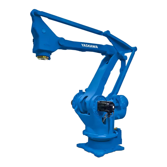
173124-1CD Basic Specifications MPL300 5.2 Part Names and Working Axes Part Names and Working Axes Fig. 5-1: Part Names and Working Axes Upper arm (U-arm) Wrist Wrist flange Lower arm (L-arm) Rotary head (S-head) Base Manipulator Base Dimensions Fig. 5-2: Manipulator Base Dimensions 220±0.1 220±0.1 +0.021... -
Page 30: Dimensions And T-Point Maximum Envelope
173124-1CD Basic Specifications MPL300 5.4 Dimensions and T-Point Maximum Envelope Dimensions and T-Point Maximum Envelope Fig. 5-3: Dimensions and T-Point Maximum Envelope 1300 1600 2776 2162 1400 R1124 2204 -Point P-point 1241 -point maximum envelope Units: mm 1037 3159 HW1482991 30 of 100... -
Page 31: Stopping Angle And Time At The Emergency Stop
173124-1CD Basic Specifications MPL300 5.5 Stopping Angle and Time at the Emergency Stop Stopping Angle and Time at the Emergency Stop Following data on stopping angle and time at the emergency stop are measured under the standard of ISO10218. 5.5.1 Stop Categiry 0: Emergency Stop 5.5.1.1 Position 100% Fig. -
Page 32: Position 66
173124-1CD Basic Specifications MPL300 5.5 Stopping Angle and Time at the Emergency Stop 5.5.1.2 Position 66% Fig. 5-5: Category 0, Position 66% : Stopping Angle and Time for each Axis at the Emergency Stop (a)S-Axis Note: L- and U-axis takes one pose only for this structure. 5.5.1.3 Position 33% Fig. -
Page 33: Stop Category 1: Emergency Stop
173124-1CD Basic Specifications MPL300 5.5 Stopping Angle and Time at the Emergency Stop 5.5.2 Stop Category 1: Emergency Stop The stopping angle and time at the emergency stop in category 1 are not subjected to the manipulator position and the load. Stop of category1 doesn't depend on the robot position and the load. -
Page 34: Alterable Operating Range
Alterable Operating Range The operating range of the S-axis can be altered in accordance with the operating conditions as shown in Table 5-2 “S-Axis Operating Range”. If alteration is necessary, contact your YASKAWA representative in advance. Table 5-2: S-Axis Operating Range... -
Page 35: Components For Altering Operating Range
173124-1CD Basic Specifications MPL300 5.6 Alterable Operating Range 5.6.1 Components for Altering Operating Range When modifying the operating range of the S-axis, prepare the components shown in Fig. 5-8 “Components of S-Axis Stopper” referring to the following list. (1) Pin (drawing No. HW0407007-1, 1 pin) (2) Stopper (drawing No. -
Page 36: Notes On The Mechanical Stopper Installation
173124-1CD Basic Specifications MPL300 5.6 Alterable Operating Range 5.6.2 Notes on the Mechanical Stopper Installation • Apply the Locktite 242 to the thread part of the pin HW0407007-1, and install the pin bottom up into the S-axis mechanical stopper HW0307574-1 as shown in Fig. 5-8 “Components of S-Axis Stopper”. Mount the stopper to the S-head with three hexagon head screws M20 (length: 70 mm) and tighten the screws to the tightening torque of 402 N•m (tensile strength: 1200 N/mm... -
Page 37: Adjustment Of The Soft Limit Of The S-Axis Pulse
173124-1CD Basic Specifications MPL300 5.6 Alterable Operating Range 5.6.3 Adjustment of the Soft Limit of the S-Axis Pulse Apply the Instruction for “DX200 Instructions chapter 8.17 Changing the Parameter Setting” as part of reference materials for adjusting the programming pendant when modifying the range of motion of S-Axis. Pulse limit (positive (+) direction of the S-axis): S1CxG400 Pulse limit (negative (-) direction of the S-axis): S1CxG408 MPL300 II... - Page 38 173124-1CD Basic Specifications MPL300 5.6 Alterable Operating Range Table 5-3: Settable Angle for S-Axis Stopper HW1482991 5-11 38 of 100...
- Page 39 173124-1CD Basic Specifications MPL300 5.6 Alterable Operating Range Fig. 5-10(a): Properly-Mounted Models for S-Axis Stopper The stopper is reversible. Either side of the stopper can be used. Hexagon head screw M20 (3 screws) (length: 70 mm) with three washers M20 Installation at + 180°...
- Page 40 173124-1CD Basic Specifications MPL300 5.6 Alterable Operating Range Fig. 5-10(b): Properly-Mounted Models for S-Axis Stopper The stopper is irreversible. Only this side of the stopper can be used at this angle. Hexagon head screw M20 (3 screws) (length: 70 mm) with three washers M20 Installation at + 150°...
- Page 41 173124-1CD Basic Specifications MPL300 5.6 Alterable Operating Range Fig. 5-10(c): Properly-Mounted Models for S-Axis Stopper The stopper is irreversible. Only this side of the stopper can be used at this angle. Hexagon head screw M20 (3 screws) (length: 70 mm) with three washers M20 Installation at + 120°...
- Page 42 173124-1CD Basic Specifications MPL300 5.6 Alterable Operating Range Fig. 5-10(d): Properly-Mounted Models for S-Axis Stopper The stopper is reversible. Either side of the stopper can be used. Hexagon head screw M20 (3 screws) (length: 70 mm) with three washers M20 Installation at + 90°...
- Page 43 173124-1CD Basic Specifications MPL300 5.6 Alterable Operating Range Fig. 5-10(e): Properly-Mounted Models for S-Axis Stopper The stopper is irreversible. Only this side of the stopper can be used at this angle. Hexagon head screw M20 (3 screws) (length: 70 mm) with three washers M20 Installation at + 60°...
- Page 44 173124-1CD Basic Specifications MPL300 5.6 Alterable Operating Range Fig. 5-10(f): Properly-Mounted Models for S-Axis Stopper Hexagon head screw M20 (3 screws) (length: 70 mm) The stopper is irreversible. with three washers M20 Only this side of the stopper can be used at this angle. Installation at + 30°...
- Page 45 173124-1CD Basic Specifications MPL300 5.6 Alterable Operating Range Fig. 5-10(g): Properly-Mounted Models for S-Axis Stopper Hexagon head screw M20 (3 screws) (length: 70 mm) with three washers M20 The stopper is reversible. Either side of the stopper can be used. Installation at + 0°...
- Page 46 173124-1CD Basic Specifications MPL300 5.6 Alterable Operating Range Fig. 5-10(h): Properly-Mounted Models for S-Axis Stopper The stopper is reversible. Either side of the stopper can be used. Hexagon head screw M20 (3 screws) (length: 70 mm) 180 ° with three washers M20 Installation at - 180°...
- Page 47 173124-1CD Basic Specifications MPL300 5.6 Alterable Operating Range Fig. 5-10(i): Properly-Mounted Models for S-Axis Stopper Hexagon head screw M20 (3 screws) (length: 70 mm) with three washers M20 The stopper is irreversible. Only this side of the stopper can be used at this angle. Installation at - 150°...
- Page 48 173124-1CD Basic Specifications MPL300 5.6 Alterable Operating Range Fig. 5-10(j): Properly-Mounted Models for S-Axis Stopper Hexagon head screw M20 (3 screws) (length: 70 mm) with three washers M20 The stopper is irreversible. Only this side of the stopper can be used at this angle. Installation at - 120°...
- Page 49 173124-1CD Basic Specifications MPL300 5.6 Alterable Operating Range Fig. 5-10(k): Properly-Mounted Models for S-Axis Stopper Hexagon head screw M20 (3 screws) (length: 70 mm) The stopper is reversible. with three washers M20 Either side of the stopper Installation at - 90° can be used.
- Page 50 173124-1CD Basic Specifications MPL300 5.6 Alterable Operating Range Fig. 5-10(l): Properly-Mounted Models for S-Axis Stopper Hexagon head screw M20 (3 screws) (length: 70 mm) with three washers M20 The stopper is irreversible. Only this side of the stopper can be used at this angle. Installation at - 60°...
- Page 51 173124-1CD Basic Specifications MPL300 5.6 Alterable Operating Range Fig. 5-10(m): Properly-Mounted Models for S-Axis Stopper Hexagon head screw M20 (3 screws) (length: 70 mm) with three washers M20 The stopper is irreversible. Only this side of the stopper can be used at this angle. Installation at - 30°...
-
Page 52: Allowable Load For Wrist Axis And Wrist Flange
173124-1CD Allowable Load for Wrist Axis and Wrist Flange MPL300 6.1 Allowable Wrist Load Allowable Load for Wrist Axis and Wrist Flange Allowable Wrist Load The allowable wrist load including the weight of the mount/gripper is 160 kg maximum. 1. The total moment of inertia (GD /4) of T-axis should be within the value shown in Table 6-1 “Allowable Total Inertia”. -
Page 53: Wrist Flange
173124-1CD Allowable Load for Wrist Axis and Wrist Flange MPL300 6.2 Wrist Flange Wrist Flange The wrist flange dimensions are shown in Fig. 6-2 “Wrist Flange”. It is recommended that the attachment be mounted inside the fitting in order to identify the alignment marks. -
Page 54: Levelness Of The Wrist Flange
173124-1CD Allowable Load for Wrist Axis and Wrist Flange MPL300 6.3 Levelness of the Wrist Flange Levelness of the Wrist Flange The wrist flange is kept level to the mounting surface of the MOTOMAN- MPL300 II in the full range of motion. However, minor tilting may occur due to the posture and load conditions. -
Page 55: System Application
173124-1CD System Application MPL300 7.1 Peripheral Equipment Mounts System Application Peripheral Equipment Mounts The peripheral equipment mounts and tapped holes are provided on the wrist unit as shown in Fig. 7-1 “Installing Peripheral Equipment” for easier installation of the users’ system applications. The following conditions shall be observed to attach or install peripheral equipment. -
Page 56: Internal User I/O Wiring Harness And Air Line
173124-1CD System Application MPL300 7.2 Internal User I/O Wiring Harness and Air Line Internal User I/O Wiring Harness and Air Line Internal user I/O wiring harness (0.5 mm x 23 wires), and air lines (5 lines ) are incorporated in the manipulator for the drive of peripheral devices mounted on the upper arm as shown in Fig. - Page 57 173124-1CD System Application MPL300 7.2 Internal User I/O Wiring Harness and Air Line Fig. 7-2(a): Connectors for Internal User I/O Wiring Harness and Air Line Cable B (See "Note 1" below.) Tube for field bus cable (inside dia.: 12) Details of Part Y (inside the junction box of the wrist) Part Y Connector for the internal user I/O...
- Page 58 173124-1CD System Application MPL300 7.2 Internal User I/O Wiring Harness and Air Line Run the field bus cable by following the steps below. Fig. 7-2(b): Field Bus Cable Connection Wire harness Union S-head Tube for field bus cable Part Z (inside dia.: 12) 1.
- Page 59 173124-1CD System Application MPL300 7.2 Internal User I/O Wiring Harness and Air Line Fig. 7-2(c): Details of the Connector Pin Numbers 11 12 18 19 20 Pins used Internal user I/O wiring harness: 23 wires, size 0.5 mm The same numbered pins (1 to 23) of the two connectors are connected with a single lead wire of 0.5 mm HW1482991 59 of 100...
- Page 60 MPL300 7.2 Internal User I/O Wiring Harness and Air Line The wrist part of MOTOMAN-MPL300 II has a hollow structure for the internal user I/O wiring harness, air line, etc. To run the internal user I/O wiring harness, air line, etc. through the hollow part, follow the conditions below.
-
Page 61: Electrical Equipment Specification
173124-1CD Electrical Equipment Specification MPL300 8.1 Position of Limit Switch Electrical Equipment Specification Position of Limit Switch The limit switches are optional. For the S-, L-, and U-axes with limit switches specifications, the limit switches are located on the S-axis, L- axis, and U-axis respectively. -
Page 62: Internal Connections
173124-1CD MPL300 II 8 Electrical Equipment Specification 8.2 Internal Connections Internal Connections Fig. 8-2(a): Internal Connection Diagram 0BAT11 0BAT1 BAT11 BAT1 0BAT12 0BAT2 S-AXIS OVERRUN L.S. Connected to BAT12 BAT2 0BAT3 BAT3 Connected to S-AXIS OVERRUN L.S. S-axis with Limit Switch Specification 0BAT21 Notes BAT21... - Page 63 173124-1CD MPL300 II 8 Electrical Equipment Specification 8.2 Internal Connections Fig. 8-2(b): Internal Connection Diagram BASE WRIST X21(8X5) 2BC(8X5) No.9CN S-AXIS No.10CN No.11CN L-AXIS No.12CN B-11 B-11 B-10 B-10 No.13CN U-AXIS No.14CN No.15CN T-AXIS No.16CN 63 of 100 HW1482991...
-
Page 64: Maintenance And Inspection
Failure to observe this caution may result in electric shock or injury. • For disassembly or repair, contact your YASKAWA representative. • Do not remove the motor, and do not release the brake. Failure to observe these safety precautions may result in death or serious injury from unexpected turning of the manipulator's arm. - Page 65 Table 9-1: Inspection Items (Sheet 1 of 2) Items Schedule Method Operation Inspection Charge • • • • Alignment mark Visual Check alignment mark accordance and damage at the home position. • • • • External lead Visual Check for damage and deterioration of leads. •...
- Page 66 1 Inspection item numbers correspond to the numbers in Fig. 9-1 “Inspection Items”. 2 The occurrence of a grease leakage indicates the possibility that grease has seeped into the motor. This can cause a motor breakdown. Contact your YASKAWA representative.
- Page 67 Fig. 9-1: Inspection Items U-axis T-axis L-axis S-axis 67 of 100...
-
Page 68: Notes On Maintenance Procedures
173124-1CD Maintenance and Inspection MPL300 9.2 Notes on Maintenance Procedures Notes on Maintenance Procedures 9.2.1 Battery Pack Replacement The battery packs are installed in the position shown in Fig. 9-2(a) “Battery Location (Back View)” and Fig. 9-2(b) “Battery Location (Top View)”. - Page 69 173124-1CD Maintenance and Inspection MPL300 9.2 Notes on Maintenance Procedures 1. Turn OFF the DX200 main power supply. 2. Remove the plate fixing screws and the plate on the connector base, then pull the battery pack out to replace it with the new one. 3.
-
Page 70: Grease Replenishment/Exchange
173124-1CD Maintenance and Inspection MPL300 9.3 Grease Replenishment/Exchange Grease Replenishment/Exchange 9.3.1 Notes on Grease Replenishment/Exchange Procedures Make sure to follow the instructions listed below at grease replenishment/ exchange. Failure to observe the following notes may result in damage to a motor and a speed reducer. •... -
Page 71: Grease Replenishment/Exchange For S-Axis Speed Reducer And Gear
173124-1CD Maintenance and Inspection MPL300 9.3 Grease Replenishment/Exchange 9.3.2 Grease Replenishment/Exchange for S-Axis Speed Reducer and Gear Fig. 9-4: S-Axis Speed Reducer and Gear Diagram Grease exhaust port Hexagon socket head plug Grease inlet Hexagon socket head plug S-axis speed reducer 9.3.2.1 Grease Replenishment (Refer to Fig. - Page 72 173124-1CD Maintenance and Inspection MPL300 9.3 Grease Replenishment/Exchange 9.3.2.2 Grease Exchange (Refer to Fig. 9-4 “S-Axis Speed Reducer and Gear Diagram”.) 1. Remove the hexagon socket head plugs from the grease inlet and grease exhaust port. • If grease is injected with the plug on, grease will leak inside the motor and may cause a damage.
-
Page 73: Grease Replenishment/Exchange For L-Axis Speed Reducer
173124-1CD Maintenance and Inspection MPL300 9.3 Grease Replenishment/Exchange 9.3.3 Grease Replenishment/Exchange for L-Axis Speed Reducer Fig. 9-5(a): L-Axis Speed Reducer Diagram L-axis speed reducer Grease exhaust port Hexagon socket head plug Grease inlet Hexagon socket head plug Section A-A' Fig. 9-5(b): L-Axis Grease Replenishment 225 mm Joint PT1/8 Grease zerk A-PT1/8... -
Page 74: Grease Replenishment
173124-1CD Maintenance and Inspection MPL300 9.3 Grease Replenishment/Exchange 9.3.3.1 Grease Replenishment (Refer to Fig. 9-5(a) “L-Axis Speed Reducer Diagram” and Fig. 9-5(b) “L-Axis Grease Replenishment”.) 1. Remove the hexagon socket head plugs from the grease inlet and grease exhaust port. •... -
Page 75: Grease Exchange
173124-1CD Maintenance and Inspection MPL300 9.3 Grease Replenishment/Exchange 9.3.3.2 Grease Exchange (Refer to Fig. 9-5(a) “L-Axis Speed Reducer Diagram”.) 1. Remove the hexagon socket head plugs from the grease inlet and grease exhaust port. • If grease is injected with the plug on, grease will leak inside the motor and may cause a damage. -
Page 76: Grease Replenishment/Exchange For U-Axis Speed Reducer
173124-1CD Maintenance and Inspection MPL300 9.3 Grease Replenishment/Exchange 9.3.4 Grease Replenishment/Exchange for U-Axis Speed Reducer Fig. 9-6: U-Axis Speed Reducer Diagram Grease exhaust port U-axis speed Grease inlet Hexagon socket head plug Hexagon socket head plug reducer 9.3.4.1 Grease Replenishment (Refer to Fig. - Page 77 173124-1CD Maintenance and Inspection MPL300 9.3 Grease Replenishment/Exchange 9.3.4.2 Grease Exchange (Refer to Fig. 9-6 “U-Axis Speed Reducer Diagram”.) 1. Remove the hexagon socket head plugs from the grease inlet and grease exhaust port. • If grease is injected with the plug on, grease will leak inside the motor and may cause a damage.
-
Page 78: Grease Replenishment/Exchange For T-Axis Speed Reducer
173124-1CD Maintenance and Inspection MPL300 9.3 Grease Replenishment/Exchange 9.3.5 Grease Replenishment/Exchange for T-Axis Speed Reducer Fig. 9-7: T-Axis Speed Reducer Diagram Grease exhaust port Hexagon socket head plug T-axis speed reducer Grease inlet Hexagon socket head plug 9.3.5.1 Grease Replenishment (Refer to Fig. - Page 79 173124-1CD Maintenance and Inspection MPL300 9.3 Grease Replenishment/Exchange If the plug is installed while grease is being exhausted, grease will leak inside the motor and may cause a damage. NOTE Make sure to install the plug when the grease exhaust is completed.
-
Page 80: Grease Replenishment For U-Axis Cross Roller Bearing
173124-1CD Maintenance and Inspection MPL300 9.3 Grease Replenishment/Exchange 9.3.6 Grease Replenishment for U-axis Cross Roller Bearing Fig. 9-8: U-Axis Cross Roller Bearing Diagram Exhaust port U-axis cross roller bearing Hexagon socket head plug Grease inlet Hexagon socket head plug 1. Remove the hexagon socket head plug of the exhaust port. (Refer to Fig. -
Page 81: Grease Replenishment For Links
173124-1CD Maintenance and Inspection MPL300 9.3 Grease Replenishment/Exchange 9.3.7 Grease Replenishment for Links Fig. 9-9: Grease Replenishment for Links HW1482991 9-18 81 of 100... - Page 82 173124-1CD Maintenance and Inspection MPL300 9.3 Grease Replenishment/Exchange 1. Remove the hexagon socket head plug PT1/8 from the exhaust port of each link. (Refer to Fig. 9-9 “Grease Replenishment for Links”) 2. Remove the hexagon socket head plug PT1/8 from the grease inlet of each link and install the grease zerk A-PT1/8.
-
Page 83: Notes For Maintenance
173124-1CD Maintenance and Inspection MPL300 9.3 Grease Replenishment/Exchange 9.3.8 Notes for Maintenance When performing maintenance such as replacement of a wire harness in the manipulator, the encoder connector may be necessary to be removed. In this case, be sure to connect the battery pack to the battery backup connector before removing the encoder connector. -
Page 84: Recommended Spare Parts
10 Recommended Spare Parts It is recommended to keep the parts and components in the following table in stock as spare parts for the MOTOMAN-MPL300 II. Product performance cannot be guaranteed when using spare parts from any company other than YASKAWA. The spare parts are ranked as follows: •... - Page 85 10 Recommended Spare Parts MPL300 Table 10-1: Spare Parts for the YR-MPL0300-J00 (Sheet 2 of 2) Rank Parts Name Type Manufacturer Remarks Unit Wire Harness in HW1172025-A YASKAWA Manipulator Electric Corporation Wire Harness in HW1372054-A YASKAWA Manipulator Electric Corporation Board...
-
Page 86: Parts List
173124-1CD 11 Parts List MPL300 11.1 S-Axis Unit 11 Parts List 11.1 S-Axis Unit Fig. 11-1: S-Axis Unit 1005 1006 1037 1039 1038 1026 1011 1034 1014 1001 1077 1022 1013 1029 1015 1078 1028 1023 1031 1035 1032 1025 1033 1024 1041... - Page 87 173124-1CD 11 Parts List MPL300 11.1 S-Axis Unit Table 11-1: S-Axis Unit (Sheet 1 of 2) DWG No. Name 1001 SGMRV-44ANA-YR1* Motor 1002 HW0281280-A Speed reducer 1003 M8X100 Socket screw 1004 2H-8 Spring washer 1005 M16X70 Socket screw 1006 2H-16 Spring washer 1011 HW0101143-1...
- Page 88 173124-1CD 11 Parts List MPL300 11.1 S-Axis Unit Table 11-1: S-Axis Unit (Sheet 2 of 2) DWG No. Name 1051 HW9405304-* Shim 1052 O-ring 1053 HW9405048-1 Housing 1054 2H-8 Spring washer 1055 M8X25 Socket screw 1056 2H-5 Spring washer 1057 M5X16 Socket screw 1058...
-
Page 89: L-Axis Unit
173124-1CD 11 Parts List MPL300 11.2 L-Axis Unit 11.2 L-Axis Unit Fig. 11-2(a): L-Axis Unit 2077 2003 2076 2055 2041 2085 2035 2058 2056 2043 2031 2076 2078 2059 2057 2077 2008 2045 2002 2041 2054 2040 2039 2067 2072 2070 2075 2074... - Page 90 173124-1CD 11 Parts List MPL300 11.2 L-Axis Unit Fig. 11-2(b): L-Axis Unit 2034 2031 2035 2035 2095 2006 2094 2039 2008 2040 2045 2045 2045 2028 2021 2016 2001 2092 2080 2086 2093 2015 2087 2017 2022 2014 2045 2018 2045 2002 2019...
- Page 91 173124-1CD 11 Parts List MPL300 11.2 L-Axis Unit Table 11-2: L-Axis Unit (Sheet 1 of 2) DWG No. Name 2001 SGMRV-44ANA-YR1* Motor 2002 HW0101144-1 L-arm 2003 HW0101146-1 Link A 2004 HW9482144-A Cross roller bearing 2005 HW9301736-1 B-cover 2006 HW9200827-1 M-base 2007 HW0200685-1 M-base...
- Page 92 173124-1CD 11 Parts List MPL300 11.2 L-Axis Unit Table 11-2: L-Axis Unit (Sheet 2 of 2) DWG No. Name 2046 HW0307641-1 Shaft 2047 HW0406922-1 B-cover 2048 HW0406923-1 Pup washer 2051 HW9405055-1 Shaft 2052 HW9405699-1 B-cover 2053 HW9302054-1 Shaft 2054 HW0308094-1 Link-C 2055 HW0400016-1...
-
Page 93: U-Axis Unit
173124-1CD 11 Parts List MPL300 11.3 U-Axis Unit 11.3 U-Axis Unit Fig. 11-3: U-Axis Unit 3022 3005 3034 3030 3030 3032 3023 3023 3032 2054 3009 3027 3023 3009 3033 3032 3022 3034 3034 3030 3022 3009 3024 3032 3030 3005 3027 3023... - Page 94 173124-1CD 11 Parts List MPL300 11.3 U-Axis Unit Table 11-3: U-Axis Unit DWG No. Name 3001 HW9403571-2 Shaft 3002 HW9301405-1 B-cover 3003 HW9403656-* Shim 3004 AG4059E0 Oil seal 3005 PT1/8 (STAINLESS) Plug 3006 HR32016XJ Bearing 3007 M6X6 Socket screw 3008 2H-6 Spring washer 3009...
-
Page 95: Wrist Unit
173124-1CD 11 Parts List MPL300 11.4 Wrist Unit 11.4 Wrist Unit Fig. 11-4: Wrist Unit 4045 4045 4022 4001 4029 4024 4017 4018 4037 4044 4012 4032 4011 4046 4010 4038 4019 4015 4020 4014 4004 4024 4033 3039 4013 3037 4008 4038... - Page 96 173124-1CD 11 Parts List MPL300 11.4 Wrist Unit Table 11-4: Wrist Unit (Sheet 1 of 2) DWG No. Name 4001 SGMRV-13ANA-YR1* Motor 4002 HW0381150-D Speed reducer 4003 HW0102580-1 Wrist base 4004 HW0406923-1 Pup washer 4005 O-ring 4006 HW0406922-1 B-cover 4007 HW0484003-A Bearing 4008...
- Page 97 173124-1CD 11 Parts List MPL300 11.4 Wrist Unit Table 11-4: Wrist Unit (Sheet 2 of 2) DWG No. Name 4045 M8X25 GT-SA Bolt 4046 M6X20 GT-SA Bolt 4047 M10X20 Socket screw 4048 2H-10 Spring washer 4049 M4X10 GT-SA Bolt 4050 M8X80 Socket screw 4051...
-
Page 98: Balancer Unit
173124-1CD 11 Parts List MPL300 11.5 Balancer Unit 11.5 Balancer Unit Fig. 11-5: Balancer Unit 5018 5019 5011 5004 5020 5007 5005 5001 5002 5006 5016 5017 5015 5012 5003 5008 5003 5012 5014 5010 5013 5009 HW1482991 11-13 98 of 100... - Page 99 173124-1CD 11 Parts List MPL300 11.5 Balancer Unit Table 11-5: Balancer Unit DWG No. Name 5001 HW0481740-A Coil spring 5002 HW0481741-A Coil spring 5003 SOB607440 OILES bearing 5004 HW0100477-1 Case 5005 HW0306033-1 Flange 5006 HW0200420-1 Flange 5007 HW0401112-1 Flange 5008 HW0303581-1 5009 HW9405057-1...
- Page 100 INSTRUCTIONS HEAD OFFICE 2-1 Kurosakishiroishi, Yahatanishi-ku, Kitakyushu 806-0004, Japan Phone +81-93-645-7703 Fax +81-93-645-7802 YASKAWA America Inc. (Motoman Robotics Division) 100 Automation Way, Miamisburg, OH 45342, U.S.A. Phone +1-937-847-6200 Fax +1-937-847-6277 YASKAWA Europe GmbH Robotics Divsion ) Yaskawastrasse 1, 85391 Allershausen, Germany...
Need help?
Do you have a question about the Motoman-MPL300 II and is the answer not in the manual?
Questions and answers