
Related Manuals for Festo CPX-CMIX-M1-1


Summary of Contents for Festo CPX-CMIX-M1-1
- Page 1 CPX Terminal Manual Electronics Measurement Module Type CPX-CMIX-M1-1 Manual 567 054 en 1208a [8021701]...
- Page 3 ....... . . 567 054 © (Festo AG & Co. KG, D-73726 Esslingen, Germany, 2012) Internet: http://www.festo.com E-Mail: service_international@festo.com...
- Page 4 Contents and general safety instructions ® ® PROFIBUS, PROFIBUS-DP, PROFINET IO , DeviceNet , RSLinx, RSLogix, RSNetworx for ® ® ® DeviceNet , EtherNet/IP and TORX are registered trademarks of the respective owners in certain countries. Festo P.BE-CPX-CMIX-EN en 1208a...
-
Page 5: Table Of Contents
..... . . 2-17 2.6.2 Power supply arrangement – formation of power zones ..2-18 Festo P.BE-CPX-CMIX-EN en 1208a... - Page 6 ......4-10 4.4.3 I/O diagnostic interface and diagnostic memory ....4-11 Festo P.BE-CPX-CMIX-EN en 1208a...
- Page 7 ............Festo P.BE-CPX-CMIX-EN en 1208a...
- Page 8 Contents and general safety instructions Festo P.BE-CPX-CMIX-EN en 1208a...
-
Page 9: Designated Use
Designated use The CPX-CMIX-C-1-H1 measuring module documented in this manual is intended exclusively for use in Festo CPX terminals for installation in a machine or an automation control system. In combinaton with a CPX terminal with suitable CPX nodes as... -
Page 10: Safety Note
Europe the standards listed under the EU machine guidelines must be observed. Without additional measures in accordance with statutory minimum requirements, the product is not suitable for use in safety-related sections of control systems. VIII Festo P.BE-CPX-CMIX-EN en 1208a... -
Page 11: Target Group
This description is intended exclusively for technicians trained in control and automation technology, who have experience in installing, commissioning, programming and diagnosing positioning systems. Service Please consult your local Festo Service if you have any technical problems. Festo P.BE-CPX-CMIX-EN en 1208a... -
Page 12: Required Software Versions
CPX-FB38 (EtherCat) CPX-CEC suitable Revisions version (R...) see type plate Tab. 0/1: Overview of CPX bus node / CPX-FEC Please also observe the notes on the software status in the documentation for the CPX node. Festo P.BE-CPX-CMIX-EN en 1208a... -
Page 13: Important User Instructions
This means that failure to observe this instruction may result in damage to property. The following pictogram marks passages in the text which describe activities with electrostatically sensitive compo- nents. Electrostatically sensitive components may be damaged if they are not handled correctly. Festo P.BE-CPX-CMIX-EN en 1208a... - Page 14 Accessories: Information on necessary or sensible accessories for the Festo product. Environment: Information on environment-friendly use of Festo products. Text markings The bullet indicates activities which may be carried out in • any order. 1. Figures denote activities which must be carried out in the numerical order specified.
-
Page 15: Notes On This Manual
Contents and general safety instructions Notes on this manual This manual refers to the following versions: – CPX-CMIX-M1-1 measuring module from ab software status V 1.0 This manual contains special information on the functioning, mounting, installation and commissioning of the CMIX measuring module with associated modules and components on the axis string (see Tab. - Page 16 – Standard cylinder with external displacement encoder (analogue, absolute – potentiometer) DSMI-... – Semi-rotary drive with integrated displacement encoder. (analogue, absolute – potentiometer) Support for other drives in preparation Tab. 0/2: Overview of modules and components Festo P.BE-CPX-CMIX-EN en 1208a...
-
Page 17: Glossary
(increments) Digital output From the point of view of the master control system, the CMIX control inputs are module output data, see section 3.3 OB / IB Output byte / input byte Festo P.BE-CPX-CMIX-EN en 1208a... - Page 18 Parameters which must be set with measuring system type potentiometer in order to be operated. These are drive length/swivel angle as well as minimum and maximum position. PLC/IPC Programmable logic controller/industrial PC Tab. 0/3: Terms and abbreviations Festo P.BE-CPX-CMIX-EN en 1208a...
-
Page 19: Overview Cpx
Overview CPX Chapter 1 Overview CPX Festo P.BE-CPX-CMIX-EN en 1208a... - Page 20 ............Festo P.BE-CPX-CMIX-EN en 1208a...
-
Page 21: Cmix Measuring Module
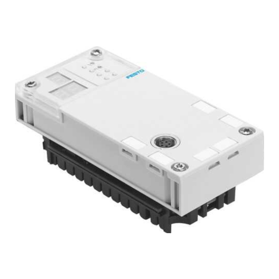
The following connection and display elements can be found on the CMIX: Status LEDs X: Control interface (connection for measuring system or sensor interface) Identification labels (accessories) 3-character display Rating plate see side Fig. 1/1: Connection and display elements of the CMIX Festo P.BE-CPX-CMIX-EN en 1208a... -
Page 22: Function Of The Cmix
CPX node (bus node or FEC) via the internal bus using 6 module output bytes and 6 module input bytes, see section 3.3. Information on commissioning the CMIX via the CPX bus node or CPX-FEC is provided in chapter 3. Festo P.BE-CPX-CMIX-EN en 1208a... -
Page 23: Layout
A sensor interface with measuring system cable (optional, depending on the measuring system used) Drive with displacement encoder (here DNCI as example) Fig. 1/2: Set-up to record positioning Specific information on the set-up is provided in chapters 2. Festo P.BE-CPX-CMIX-EN en 1208a... - Page 24 1. Overview CPX Festo P.BE-CPX-CMIX-EN en 1208a...
-
Page 25: Fitting And Installation
Fitting and installation Chapter 2 Fitting and installation Festo P.BE-CPX-CMIX-EN en 1208a... - Page 26 ..... . . 2-17 2.6.2 Power supply arrangement – formation of power zones ..2-18 Festo P.BE-CPX-CMIX-EN en 1208a...
-
Page 27: General Notes On Fitting And Installation
The use of components that have not been approved for operation with the CMIX may lead to malfunctions. Use only the special matching components from Festo for setting up and wiring the system. When fitting the pneumatic components, observe also the notes on fitting in the operating instructions supplied and the notes on installation in this chapter. -
Page 28: Fitting And Removing The Cmix
1. Loosen the four screws of the CMIX with a T10 TORX screwdriver. 2. Pull the CMIX carefully and without tilting away from the power rails of the interlinking block. CMIX Interlocking block Contact rails TORX T10 screws Fig. 2/1: Removal/fitting of the CMIX Festo P.BE-CPX-CMIX-EN en 1208a... - Page 29 0.9 ... 1.1 Nm. The parameterisation is saved in the CMIX. Therefore, after replacing a CMIX, check the parameters and, if necessary, repeat the commissioning process; see chapter 3. Observe the instructions in section A.4. Festo P.BE-CPX-CMIX-EN en 1208a...
-
Page 30: Installation Of The Drive And Displacement Encoder
2. Fitting and installation Installation of the drive and displacement encoder Use the permitted combinations of drives and measuring systems approved by Festo for the CMIX. The following drives can be used: Drive Measuring system Sensor interface Design Type Function... -
Page 31: General Requirements Of The Mechanics
Please observe the notes in the operating instructions for the axis used. Make sure that: – the permitted lateral force, – the permitted longitudinal force, – the permitted mass moment of inertia, – the maximum permitted speeds and swivel frequencies are observed. Festo P.BE-CPX-CMIX-EN en 1208a... - Page 32 External displacement encoder Always leave the measuring system mounted already mounted on delivery on the standard cylinder • Observe the notes in the operating manual DSMI Integrated displacement encoder – Tab. 2/2: Notes on mounting the displacement encoder Festo P.BE-CPX-CMIX-EN en 1208a...
-
Page 33: Mounting The Casm
Tightening torque: 2 Nm. Fastening screw (connect earthing) Fig. 2/2: Mounting the CASM-... Fastening on H-rails as per EN 60715 is possible with mounting kit type CP-TS-HS35; see Fig. 2/3. H-rail Fig. 2/3: Mounting the CASM-... on H-rails Festo P.BE-CPX-CMIX-EN en 1208a... -
Page 34: Electrical Installation
(typically 20 ... 30 cm). Sensor interface earthing When using a sensor interface: Make a low-ohm connection between the earthing con- • nection of the sensor interface and the earth potential of the CPX terminal. 2-10 Festo P.BE-CPX-CMIX-EN en 1208a... - Page 35 Make a low-ohm connection (earthing strap) displacement encoder between the earth connection of the DSMI and the earth potential! Alternatively: Mount the drive on an earthed machine bed. Tab. 2/3: Notes on earthing the drive and displacement encoder 2-11 Festo P.BE-CPX-CMIX-EN en 1208a...
-
Page 36: Axis Connection
+24 V load voltage CAN_H CAN_L Housing Cable shield Cable screening on CASM connected to the earth terminal, screening for DGCI or DDLI connected to the housing. Tab. 2/4: Pin allocation of the axis connections 2-12 Festo P.BE-CPX-CMIX-EN en 1208a... -
Page 37: Permissible Module And String Lengths
0.5 m KVI-CP-3-WS-WD-0,5 KVI-CP-3-WS-WD-2 KVI-CP-3-WS-WD-5 KVI-CP-3-WS-WD-8 Connecting cable GS-GD, KVI-CP-3-GS-GD-2 straight plug – straight socket KVI-CP-3-GS-GD-5 KVI-CP-3-GS-GD-8 Connecting piece, – KVI-CP-3-SSD for control cabinet feed-through Tab. 2/5: Overview of cables between CMIX, sensor interface, measuring system 2-13 Festo P.BE-CPX-CMIX-EN en 1208a... -
Page 38: Sensor Interface Casm
– If the potentiometer has worse values for linearity and temperature coefficient, the measured value will be less accurate. – To connect it to the sensor interface, you might have to fabricate a special cable. 2-14 Festo P.BE-CPX-CMIX-EN en 1208a... - Page 39 Signal cosine – Signal cosine + Screening n.c. (not connected) Housing Earthing connection (FE) The cable screening is connected to the earthing terminal of the sensor interface. Tab. 2/7: Pin assignment of connection S2 with the CASM-S-D3-R7 2-15 Festo P.BE-CPX-CMIX-EN en 1208a...
-
Page 40: Ensuring Protection Class Ip65
In order to achieve protection class IP65: Seal unused connections with the protective caps • supplied. If the axis connection is not used, then seal this using a FLANSCHDOSE (flangesocket), S712 protective cap. You will then achieve protection class IP65. 2-16 Festo P.BE-CPX-CMIX-EN en 1208a... -
Page 41: Power Supply
Current consumption of the CMIX made up of V EL/SEN the CPX terminal Typical current consumption dependent on the 80 ... 110 mA measuring system Maximum current consumption 110 mA Tab. 2/9: Current consumption via V of the EL/SEN CPX terminal 2-17 Festo P.BE-CPX-CMIX-EN en 1208a... -
Page 42: Power Supply Arrangement - Formation Of Power Zones
CPX-GE-EV-V interlinking block is located to the left of the CMIX because this can remove an intentional voltage isolation. Basic information on the power supply arrangement of the CPX terminal can be found in the CPX system manual. 2-18 Festo P.BE-CPX-CMIX-EN en 1208a... -
Page 43: Commissioning
Commissioning Chapter 3 Commissioning Festo P.BE-CPX-CMIX-EN en 1208a... - Page 44 Resetting to status as at delivery ........3-18 Festo P.BE-CPX-CMIX-EN en 1208a...
-
Page 45: Overview / Procedure For Commissioning
– Potentiometer (e.g. MLO-POT-..., DSMI, DNCM): The min. and max. position value must be set once and the effective stroke length (max. measurement length) written in 1/100 mm. After commissioning: 5. Check function of the CMIX. Festo P.BE-CPX-CMIX-EN en 1208a... -
Page 46: Notes On The Available Cpx Nodes
Not present Tab. 3/1: Note, CPX node Depending on the bus, up to 9 CMIX can be installed in one CPX terminal. General parameterisation instructions are provided in the respective manuals for the CPX node used. Festo P.BE-CPX-CMIX-EN en 1208a... -
Page 47: I/O Assignment Of The Cmix / Address Range
16 bit after the decimal Input data Actual value: position or speed Status byte Reserved SCON 16 bit before the decimal 16 bit after the decimal Tab. 3/3: Module output data of the CMIX with decimal format Festo P.BE-CPX-CMIX-EN en 1208a... -
Page 48: Control Byte And Status Byte Assignment
Assignment of the status byte SCON (byte 4) SCON ERROR – REF_OK ERROR3 ERROR2 ERROR1 ERROR0 Errors – Para- Refe- Error code meter rence accepted point set Tab. 3/5: Byte 4 of the module input data of the CMIX: SCON Festo P.BE-CPX-CMIX-EN en 1208a... - Page 49 (the effective stroke length is not considered). For the potentiometer, the max. position, min. position and effective stroke length or swivel angle must be entered; see section 3.4.3. For swivel modules, the unit 0.01° is valid correspondingly. Festo P.BE-CPX-CMIX-EN en 1208a...
- Page 50 = 0: No parameter acknowledgement (LOAD_P = 0) nommen Parameter = 1: Parameter acknowledged LOAD_P can be reset to 0 – – Reserved (= 0) – Fehler Error Error bit. ERROR = 0: No error = 1: Error present; see B0 ... B3 Festo P.BE-CPX-CMIX-EN en 1208a...
-
Page 51: Data Format Of Actual Value And Setpoint Value
7 6 5 4 3 2 1 0 7 6 5 4 3 2 1 0 7 6 5 4 3 2 1 0 7 6 5 4 3 2 1 0 0 0 0 0 0 0 0 0 0 0 0 0 0 0 0 1 0 0 1 0 0 1 0 0 1 1 1 1 1 0 0 0 Festo P.BE-CPX-CMIX-EN en 1208a... -
Page 52: Notes On Displaying Speed
For the potentiometer or encoder (DNCI, DDPC), after-decimal digits are putput, since for the potentiometer the effective stroke length is divided by 65535 and for the encoder an increment is calculated as 4.8828 μm. 3-10 Festo P.BE-CPX-CMIX-EN en 1208a... -
Page 53: Commissioning With Various Drives/Measuring Systems
REF in the control byte CCON. Confirmation takes place via the bits ACK = 1 and REF_OK = 0 in the status byte SCON. Negative values are output below the zero point, positive values above it. 3-11 Festo P.BE-CPX-CMIX-EN en 1208a... -
Page 54: Potentiometer (Mlo
1/100°. That is, an entry of 27000 (32-bit integer) or 270.00 (decimal) equals the nominal swivel angle of 270°. But the exact angle between the stops can differ from it. 3-12 Festo P.BE-CPX-CMIX-EN en 1208a... - Page 55 Tip: You can also perform all one-time settings with the CPX-FMT. Fig. 3/4 shows the effective stroke length being written as an example. Fig. 3/4: Writing the effective stroke length with the CPX-FMT 3-13 Festo P.BE-CPX-CMIX-EN en 1208a...
-
Page 56: Examples
Byte 3 Byte 4 Byte 5 Bit 7 ... 0 XXXXXXXX XXXXXXXX XXXXXXXX XXXXXXXX 00100000 00000000 Hex. 0xXX 0xXX 0xXX 0xXX 0x20 0x00 Description X: Not relevant Bit 5: Pos. accepted Reserved Bit 7: No error 3-14 Festo P.BE-CPX-CMIX-EN en 1208a... - Page 57 Byte 3 Byte 4 Byte 5 Bit 7 ... 0 XXXXXXXX XXXXXXXX XXXXXXXX XXXXXXXX 00100000 00000000 Hex. 0xXX 0xXX 0xXX 0xXX 0x20 0x00 Description Bit 5: Pos. accepted X: Not relevant Reserved Bit 7: No error 3-15 Festo P.BE-CPX-CMIX-EN en 1208a...
- Page 58 Effective stroke length setpoint value, Bit 0: Unit 0.01 mm Reserved example 485 mm (Z 48500 = 0x0000BD74) Bit 1: Format 32-bit int. Bit 2: Position mode Bit 5: Accept length Bit 6, 7: Effective stroke length 3-16 Festo P.BE-CPX-CMIX-EN en 1208a...
- Page 59 Bit 7: No error Example decimal format In the decimal format, all values (position values, effective stroke length, etc.) are interpreted as follows: L = 488.02 mm before decimal = 488 (0x01E8) after decimal = 02 (0x0002) 3-17 Festo P.BE-CPX-CMIX-EN en 1208a...
-
Page 60: Resetting To Status As At Delivery
5. Switch off power supply of the CPX terminal. 6. Plug cable back in to the measuring system or sensor interface. 7. Switch on power supply of the CPX terminal. The CMIX is back in the delivery condition. 3-18 Festo P.BE-CPX-CMIX-EN en 1208a... -
Page 61: Diagnosis
Diagnosis Chapter 4 Diagnosis Festo P.BE-CPX-CMIX-EN en 1208a... - Page 62 ......4-10 4.4.3 I/O diagnostic interface and diagnostic memory ....4-11 Festo P.BE-CPX-CMIX-EN en 1208a...
-
Page 63: Errors Of The Cmix
Value of the error bits ERROR0 ... ERROR3 For potentiometer, the error does not have to be acknowledged after its cause is repaired 100 ≥ Effective stroke ≥ 500000 Tab. 4/1: Error messages of the CMIX Festo P.BE-CPX-CMIX-EN en 1208a... -
Page 64: Acknowledging Errors
Errors can basically only be acknowledged after the cause of the error has been rectified. In order to delete the error: – acknowledge the error with the RESET_FAULT bit – switch the operating voltage off and then on again. Festo P.BE-CPX-CMIX-EN en 1208a... -
Page 65: Diagnostics Via Leds
The light-emitting diodes on the cover indicate CMIX errors. Errors P (red) Power Load PL (not used) Fig. 4/1: LEDs at the CMIX Description Error LED Lights up when CMIX errors occur. Power Load Not used by CMIX Tab. 4/3: LEDs of the CMIX Festo P.BE-CPX-CMIX-EN en 1208a... -
Page 66: Leds On The Sensor Interface
Error: Sensor cable (cable break in the sensor cable) green flashes red 3 times Error: Supply voltage (< 17 V for longer than 15 ms) green flashes red 4 times Error: Communication error (Bus Off state) Festo P.BE-CPX-CMIX-EN en 1208a... -
Page 67: Leds On The Measuring System (Dgci Only)
Status green No error (normal operating status) No power supply Error: Initialising via CAN failed green Error: Magnet not recognised or incorrect number of magnets flashes green flashes red Error: Operating voltage not within permissible range Festo P.BE-CPX-CMIX-EN en 1208a... -
Page 68: Diagnosis Via The Display/7-Segment Display
Measuring system is not present/defective, communication error or time out E81: Checksum error in the measuring system. Impermissible entry of the effective stroke length (100 ≥ Effective stroke ≥ 500000) Undervoltage measuring system Measuring system defective Tab. 4/4: Status information display Festo P.BE-CPX-CMIX-EN en 1208a... -
Page 69: Diagnosis Via The Cpx Node
Error exists The ERROR bit shows that an error is present. With the RESET bit, the error can be acknowledged. Error number The error number of an existing error is provided in the bits ERROR0 ... 3. Festo P.BE-CPX-CMIX-EN en 1208a... -
Page 70: Status Bits Of The Cpx Terminal
– Short circuit/overload – Wire break – Other error – Tab. 4/5: Overview of status bits Further instructions on the function and content of the status bits can be found in the CPX system manual. 4-10 Festo P.BE-CPX-CMIX-EN en 1208a... -
Page 71: I/O Diagnostic Interface And Diagnostic Memory
(diagnostic event) [NB] = 0 ... 39; most current diagnostic event = 0 Tab. 4/6: Diagnostic memory data of the CMIX Instructions on diagnosis with the I/O diagnostic interface can be found in the CPX system manual. 4-11 Festo P.BE-CPX-CMIX-EN en 1208a... - Page 72 5 ... 0 Description 10000000 0 ... 0 Error in I channel Error number [FN] CPX error number: 108 01101100 Following channels Always 0 for the CMIX 00000000 Tab. 4/7: Example of diagnostic memory entry 4-12 Festo P.BE-CPX-CMIX-EN en 1208a...
- Page 73 = module number (0 ... 47) Description Error number Bit 0 ... 7 Error number Values CPX error number, (see example Tab. 4/7) Remark For CMIX error messages, see section 4.1 Tab. 4/9: Module error number 4-13 Festo P.BE-CPX-CMIX-EN en 1208a...
- Page 74 784 + m*4 + 3 Serial number of the module. byte 0: lower nibble = year, higher nibble = month of the series. bytes 1 ... 3: each nibble contains one digit of the serial number (BCD encoded) 4-14 Festo P.BE-CPX-CMIX-EN en 1208a...
-
Page 75: A. Technical Appendix
Technical appendix Appendix A Technical appendix Festo P.BE-CPX-CMIX-EN en 1208a... - Page 76 ........A-11 Festo P.BE-CPX-CMIX-EN en 1208a...
-
Page 77: Technical Data Cmix
> 1 ms causes error E80) CMIX measuring system connection Axis string Number of axis strings / Number of axes 1 / 1 Max. total length (all cables) 30 m Type of axis connection Socket M9, 5-pin Festo P.BE-CPX-CMIX-EN en 1208a... -
Page 78: Components And Accessories
(in this example a DGC with interface, connection MLO-POT-...-LWG) and possibly a sensor cables and, if present, interface (depending on the measuring additional fixed stops system) Tab. A/1: Components with the CMIX Festo P.BE-CPX-CMIX-EN en 1208a... -
Page 79: Supported Drives Or Measuring Systems
(potentiometer) on the axis string Connection cable for Connection cable between a NEBC-A1W3-K- the measuring system CASM-S-D2-R3 and an MLO-POT-...-TLF 0.3-N-M12G5 Tab. A/3: Components with DGP(L) linear drive and MLO-POT-...-TLF measuring system Festo P.BE-CPX-CMIX-EN en 1208a... - Page 80 (potentiometer) on the axis string Connection cable Connection cable between a NEBC-P1W4-K- for the measuring CASM-S-D2-R3 and an MLO-POT-...-LWG 0.3-N-M12G5 system Tab. A/5: Components with DNC standard cylinder and MLO-POT-...-LWG displacement encoder Festo P.BE-CPX-CMIX-EN en 1208a...
- Page 81 Sensor interface for connection to an CASM-S-D2-R3 analogue absolute displacement encoder (potentiometer) on the axis string Connection cable Connection cable between a NEBC-P1W4-K- for the measuring CASM-S-D2-R3 and a DSMI 0.3-N-M12G5 system Tab. A/7: Components with DSMI semi-rotary drive Festo P.BE-CPX-CMIX-EN en 1208a...
-
Page 82: Characteristic Values For Various Measuring Systems
Characteristic values for encoder (DNCI, DDPC) Entire system linearity ≤ ±0.07 mm . ±0.02 mm Repetition accuracy . 0.03 mm Hysteresis Max. speed of travel 1 m/s Smallest measurable speed 10 mm/s Tab. A/9: Characteristic values for encoder Festo P.BE-CPX-CMIX-EN en 1208a... - Page 83 Repetition accuracy (± in mm) 0.019 0.023 0.03 0.038 0.046 0.054 0.062 Max. speed of travel 3 m/s Smallest measurable speed (mm/s) Temperature coefficient 5 ppm/° C Tab. A/11: Characteristic values for potentiometer 600 ... 2000 Festo P.BE-CPX-CMIX-EN en 1208a...
-
Page 84: Replacing Components
Note, however, that the reference system may change when the drive or measuring system is replaced! ... of other Identical electrical components, such as the sensor interface, can be replaced components without further changes. Tab. A/12: Replacing components A-10 Festo P.BE-CPX-CMIX-EN en 1208a... -
Page 85: Display With The Handheld Unit
0 equals the position in whole millimetres, the value of input channel 1 the decimal places in 1/100 milli- metres. The values in Fig. A/1 thus equal the position 425.04 mm, for example. A-11 Festo P.BE-CPX-CMIX-EN en 1208a... - Page 86 Fig. A/2: Displaying information with the handheld unit Module data Description Type code Module code (CPX-specific, for the CMIX: 180) Revision Revision status of the CMIX Serial No Serial number of the CMIX Tab. A/13: Module data on the handheld unit A-12 Festo P.BE-CPX-CMIX-EN en 1208a...
-
Page 87: B. Configuration With Cpx Node
Configuration with CPX node Appendix B Configuration with CPX node Festo P.BE-CPX-CMIX-EN en 1208a... - Page 88 ..........B-26 Festo P.BE-CPX-CMIX-EN en 1208a...
-
Page 89: Cpx-Fec
Detailed information on operating the FST can be found in the FST manual (type P.BE-FST-...). B.1.1 Configuration Use Festo Software Tools (FST 4.1 or higher) with the Hardware Configurator in order to configure your CPX terminal with CPX-FEC. To configure the CMIX, this must be in the catalogue of the CPX configurator (CPX terminal / Technology module / CPX-CMIX...). - Page 90 With manual configuration, the CMIX can initially be configured without a connection to the CPX terminal. Configuration with drag & drop Configured modules in the configuration table Fig. B/1: Manual configuration of the CPX terminal in the Hardware Configurator Festo P.BE-CPX-CMIX-EN en 1208a...
-
Page 91: Parameterising The Cmix
CPX-FEC (a program must exist for this). Note Make sure that you have supplied taught parameters, or parameters edited via the keyboard or the CPX-MMI, to the CPX configurator. Festo P.BE-CPX-CMIX-EN en 1208a... -
Page 92: Address Assignment
2-way analogue input module (2AI) 64, 65 – – – MPA pneumatic interface – – Passive module MPA pneumatic module – – (CPX-Typ32: 1-8V) – – Tab. B/2: Configuration of address assignment for example Fig. B/2 Festo P.BE-CPX-CMIX-EN en 1208a... - Page 93 – (reserved) O131.8 ... 15 – (reserved) I131.8 ... 15 For decimal format OW / IW : output word / input word Tab. B/3: Addresses of the CMIX input and output bytes in the example Fig. B/2 Festo P.BE-CPX-CMIX-EN en 1208a...
-
Page 94: Diagnosis
Hardware Configurator with an icon on the appropriate module: View current diagnostic message View diagnostic memory (properties or module entry) (context menu) Fig. B/3: Warning icon as diagnostic message in the Hardware Configurator Festo P.BE-CPX-CMIX-EN en 1208a... - Page 95 View current diagnostic message Diagnostic message in the Hardware Configurator. • Display the “Diagnosis” tab of the “Module...” dialog by • double-clicking or via the [Properties] context menu. Fig. B/4: Diagnostic message in the Properties dialog Festo P.BE-CPX-CMIX-EN en 1208a...
- Page 96 Fig. B/5: Tarce memory Diagnosis with the online control panel Select [Online] [Control Panel]. • Coded diagnostic information is displayed under “Error”: Error type, CPX error number, module number Fig. B/6: FST online control panel B-10 Festo P.BE-CPX-CMIX-EN en 1208a...
- Page 97 Enter it as “Error program” in the register “Run mode” in the “Controller settings”. STEP “Wait for fault quitting E0.7 ’Reset FEC Error THEN RESET ’Error LOAD ’Fault word RESET ’Fault quitting ’General - organisational Fig. B/7: Sample extract from an error program B-11 Festo P.BE-CPX-CMIX-EN en 1208a...
-
Page 98: Cpx-Fb13 (Profibus-Dp
CMIX 6 bytes I, 6 bytes O measuring module Device master file (GSD file) and icon files Obtainable from Current GSD files and icon files can be found on the Festo Internet pages at: www.festo.com Downloads Download Area: Software, Drivers and firmware... -
Page 99: Configuration With Step
1. Add a DP master system 1 and the CPX terminal 2 to the CPX-FB13, as per the instructions. 2. Fill the configuration table with the modules of your CPX system. Open the component “Festo CPX-Terminal” in the Hardware Catalogue (file \PROFIBUS-DP\Additional Field Devices\Valves\...) 3. There are two entries for the CMIX:... - Page 100 B. Configuration with CPX node Fig. B/8: Configuration with STEP7 – Hardware catalogue B-14 Festo P.BE-CPX-CMIX-EN en 1208a...
-
Page 101: Parameterisation
Value “1”: MOTOROLA (MSB-LSB) Fig. B/9: CPX parameter “Analogue process value presentation” Note the byte order of the actual and setpoint values when using the INTEL format; see section B.2.4. General information can be found in section 3.3.2. B-15 Festo P.BE-CPX-CMIX-EN en 1208a... -
Page 102: Addressing
7 ... 8 8-way digital input module (E: CPX-8DE) – 4-way digital output module (A : CPX-4DA 2x) – CMIX (CPX-CMIX-M1-1) measuring module, 10 ... 15 10 ... 15 for assignments, see Tab. B/6 Analogue input module (A : CPX4AE-I) 16 ... - Page 103 Tab. B/6: Addresses of the CMIX input and output bytes in the example Fig. B/10 (INTEL format) The following examples show a variable table each for various format and data formats; see also section 3.3. B-17 Festo P.BE-CPX-CMIX-EN en 1208a...
- Page 104 EW 102 (IW102) EB100 EB101 EB102 EB103 (IB100) (IB101) (IB102) (IB103) 0x00 0x01 0x7F 0x70 Result 32-bit integer ED100 (ID100) 0x00017F70 98160 [1/100 mm] Tab. B/7: Variable table example: actual position, 32 bit integer, MOTOROLA format B-18 Festo P.BE-CPX-CMIX-EN en 1208a...
- Page 105 (IB102) (IB103) 0x00 0x3C 0x03 0xD5 After the decimal Before the decimal Result: Before the After the decimal decimal EW102 (IW102) EW100 (IW100) 0x03D5 0x003C Tab. B/8: Variable table example: actual position, decimal, MOTOROLA format B-19 Festo P.BE-CPX-CMIX-EN en 1208a...
- Page 106 I bytes in the right order Marker double word MD100 MB100 MB101 MB102 MB103 0x00 0x01 0x7F 0x70 Result: 32-bit integer MD100 0x00017F70 98160 [1/100 mm] Tab. B/9: Variable table example: actual position, 32 bit integer, INTEL format B-20 Festo P.BE-CPX-CMIX-EN en 1208a...
- Page 107 MB100 MB101 MB102 MB103 0x00 0x3C 0x03 0xD5 After the decimal Before the decimal Result: Before the After the decimal decimal MW102 MW100 0x03D5 0x003C Tab. B/10: Variable table example: actual position, decimal, INTEL format B-21 Festo P.BE-CPX-CMIX-EN en 1208a...
- Page 108 Format 32-bit integer Data format MOTOROLA Input in the output data: 0x00005780 22400 AB120 AB121 AB122 AB123 (QB120) (QB121) (QB122) (QB123) 0x00 0x00 0x57 0x80 Tab. B/11: Variable table example: effective stroke, 32 bit integer, MOTOROLA format B-22 Festo P.BE-CPX-CMIX-EN en 1208a...
- Page 109 Format 32-bit integer INTEL data format Input in the output data: 0x00005780 22400 AB120 AB121 AB122 AB123 (QB120) (QB121) (QB122) (QB123) 0x80 0x57 0x00 0x00 Tab. B/12: Variable table example: effective stroke, 32 bit integer, INTEL format B-23 Festo P.BE-CPX-CMIX-EN en 1208a...
-
Page 110: Cpx-Fb11 (Devicenet)
Reference source for EDS files Reference source Current EDS files, icon files and information on the EDS files can be found under the following address in Internet: www.festo.com Downloads Download Area: Software, Drivers and firmware Enter search term: CMIX B-24 Festo P.BE-CPX-CMIX-EN en 1208a... - Page 111 The CPX terminal or the modules will then be represented accordingly in the configuration program. Notes on installing the EDS files and the icon files can be found in the documentation for your configuration program. B-25 Festo P.BE-CPX-CMIX-EN en 1208a...
-
Page 112: Parameterising
1. Double-click on the scanner in the network. A dialogue box will open. 2. With the registers “Input” and “Output”, you assign the I/O addresses of the CPX terminal to the PLC operands. Fig. B/11: Output address assignment B-26 Festo P.BE-CPX-CMIX-EN en 1208a... - Page 113 Module no.: 0 CPX-FB11 (with status bits) Analogue I/O modules Digital I/O modules MPA pneumatics (2 pneumatic modules) CMIX technology module Fig. B/12: CPX example terminal 3 (address example for scanner 1747-SDN, see Tab. B/14) B-27 Festo P.BE-CPX-CMIX-EN en 1208a...
-
Page 114: Addressing
O:1.3.0 ... O:1.3.15 Analogue 2-input module O:1.2.0 ... O:1.2.15 – CPX-2AE O:1.3.0 ... O:1.3.15 MPA1 pneumatic module – O:1.4.8 ... O:1.4.15 MPA1 pneumatic module – O:1.5.0 ... O:1.5.7 Tab. B/14: Addressing example for scanner 1747-SDN B-28 Festo P.BE-CPX-CMIX-EN en 1208a... - Page 115 O:1.6.5 I:1.3.5 PARAM0 O:1.6.6 – I:1.3.6 PARAM1 O:1.6.7 ERROR I:1.3.7 – (reserved) O:1.6.8 ... 15 – (reserved) I:1.3.8 ... 15 Tab. B/15: Addresses of the CMIX input and output bytes in the example Fig. B/12 B-29 Festo P.BE-CPX-CMIX-EN en 1208a...
- Page 116 B. Configuration with CPX node B-30 Festo P.BE-CPX-CMIX-EN en 1208a...
- Page 117 Index Appendix C Index Festo P.BE-CPX-CMIX-EN en 1208a...
-
Page 118: C. Index
C. Index Festo P.BE-CPX-CMIX-EN en 1208a... - Page 119 ......... Festo P.BE-CPX-CMIX-EN en 1208a...
- Page 120 ......4-13 Number of the first faulty channel ....4-13 Festo P.BE-CPX-CMIX-EN en 1208a...
- Page 121 Trace memory ........B-10 Festo P.BE-CPX-CMIX-EN en 1208a...
- Page 122 C. Index Festo P.BE-CPX-CMIX-EN en 1208a...
Need help?
Do you have a question about the CPX-CMIX-M1-1 and is the answer not in the manual?
Questions and answers