
Subscribe to Our Youtube Channel
Related Manuals for Planet Networking & Communication WGSW-50040


Summary of Contents for Planet Networking & Communication WGSW-50040
- Page 1 Configuration Guide WGSW-50040 50-Port 10/100/1000Mbps with 4 Shared SFP Managed Gigabit Switch...
-
Page 2: Fcc Warning
Saving the Energy and reduce the unnecessary power consuming, it is strongly suggested to remove the power connection for the device if this device is not intended to be active. Revision PLANET 50-Port 10/100/1000Mbps with 4 Shared SFP Managed Gigabit Switch User's Manual FOR MODEL: WGSW-50040 REVISION: 1.0 (AUGUST.2010) Part No: EM-WGSW-50040 (2081-A93200-000) -
Page 3: Table Of Contents
Content CHAPTER 1 INTRODUTION ................... 1-1 1.1 P ..........................1-1 ACKET ONTENTS 1.2 P ........................1-1 RODUCT ESCRIPTION 1.3 P ........................... 1-3 RODUCT EATURES 1.4 P ........................1-2 RODUCT PECIFICATION CHAPTER 2 INSTALLATION ..................2-1 2.1 H ........................2-1 ARDWARE ESCRIPTION 2.1.1 Switch Front Panel ........................ - Page 4 4.4.4 SNMP Configuration ....................... 4-9 4.4.5 Typical SNMP Configuration Examples ................4-11 4.4.6 SNMP Troubleshooting ......................4-13 4.5 S ..........................4-13 WITCH PGRADE 4.5.1 Switch System Files ......................4-13 4.5.2 BootROM Upgrade ........................ 4-14 4.5.3 FTP/TFTP Upgrade ....................... 4-16 CHAPTER 5 CLUSTER CONFIGURATION ..............5-1 5.1 I ................
- Page 5 10.1.3 Typical VLAN Application ....................10-4 10.2 GVRP C ........................10-5 ONFIGURATION 10.2.1 Introduction to GVRP ......................10-5 10.2.2 GVRP Configuration Task List ..................... 10-6 10.2.3 Typical GVRP Application ....................10-7 10.2.4 GVRP Troubleshooting ....................... 10-8 10.3 D ..................... 10-8 TUNNEL ONFIGURATION 10.3.1 Introduction to Dot1q-tunnel ....................
- Page 6 13.1 I S ........................13-1 NTRODUCTION TO 13.1.1 QoS Terms .......................... 13-1 13.1.2 QoS Implementation ......................13-2 13.1.3 Basic QoS Model ........................ 13-2 13.2 Q ..................... 13-6 ONFIGURATION 13.3 Q ..........................13-10 XAMPLE 13.4 Q ....................... 13-12 ROUBLESHOOTING CHAPTER 14 FLOW-BASED REDIRECTION .............14-13 14.1 I ................
- Page 7 18.4 DHCP T ......................18-5 ROUBLESHOOTING CHAPTER 19 DHCP SNOOPING CONFIGURATION ...........19-1 19.1 I DHCP S ....................19-1 NTRODUCTION TO NOOPING 19.2 DHCP S ................ 19-2 NOOPING ONFIGURATION EQUENCE 19.3 DHCP S ..................19-5 NOOPING YPICAL PPLICATION 19.4 DHCP S ..................
- Page 8 23.1 I VLAN ..................... 23-1 NTRODUCTIONS TO ULTICAST 23.2 M VLAN C ................. 23-1 ULTICAST ONFIGURATION 23.3 M VLAN E ......................23-2 ULTICAST XAMPLES CHAPTER 24 ACL CONFIGURATION ................24-4 24.1 I ACL ........................24-4 NTRODUCTION TO 24.1.1 Access-list ........................... 24-4 24.1.2 Access-group ........................
- Page 9 27.3 AM F ........................27-3 UNCTION XAMPLE 27.4 AM F ....................27-3 UNCTION ROUBLESHOOTING CHAPTER 28 SECURITY FEATURE CONFIGURATION ..........28-1 28.1 I ..................... 28-1 NTRODUCTION TO ECURITY EATURE 28.2 S ....................28-1 ECURITY EATURE ONFIGURATION 28.2.1 Prevent IP Spoofing Function Configuration Task Sequence ..........28-1 28.2.2 Prevent TCP Unauthorized Label Attack Function Configuration Task Sequence .....
- Page 10 32.3 M ........................32-16 IRROR XAMPLES 32.4 D ....................32-17 EVICE IRROR ROUBLESHOOTING CHAPTER 33 SFLOW CONFIGURATION ..............33-18 33.1 I ......................33-18 NTRODUCTION TO S 33.2 ....................33-18 ONFIGURATION 33.3 ......................... 33-20 XAMPLES 33.4 ......................33-20 ROUBLESHOOTING CHAPTER 34 SNTP CONFIGURATION ..............34-22 34.1 I SNTP .......................
-
Page 11: Chapter 1 Introdution
QoS and RADIUS authentication besides the IPv4 protocol supported. Supporting IPv6 management features and also backward compatible with IPv4, the WGSW-50040 helps the enterprises to step in the IPv6 era with the lowest investment but not need to replace the network facilities while the ISP construct the IPv6 FTTx edge network. - Page 12 The WGSW-50040 provides 802.1Q Tagged VLAN, Q-in-Q, voice VLAN and GVRP protocol. The VLAN groups allowed on the WGSW-50040 will be maximally up to 256. By supporting port aggregation, the WGSW-50040 allows the operation of a high-speed trunk combining multiple ports. It enables up to 8 groups of maximum 8-ports for trunking.
-
Page 13: Product Features
1.3 Product Features Physical Port 50-Port 10/100/1000Base-T Gigabit Ethernet RJ-45 4 mini-GBIC/SFP slots, shared with Port-45 to Port-48 RJ-45 to DB9 console interface for Switch basic management and setup IP Stacking Connects with stack member via both Gigabit TP/SFP interface ... - Page 14 Quality of Service 8 priority queues on all switch ports Supports for strict priority and Weighted Round Robin (WRR) CoS policies Traffic classification: IEEE 802.1p CoS / ToS IPv4 / IPv6 DSCP Port-Based QoS Strict priority and Weighted Round Robin (WRR) CoS policies ...
-
Page 15: Product Specification
1.4 Product Specification WGSW-50040 Product 50-Port 10/100/1000Mbps with 4 Shared SFP Managed Gigabit Switch Hardware Specification Copper Ports 50 10/ 100/1000Base-T RJ-45 Auto-MDI/MDI-X ports SFP / mini-GBIC Slots 4 1000Base-SX/LX SFP interfaces, shared with Port-45 to Port-48 Switch Architecture Store-and-Forward... - Page 16 The right configuration for users to adopt radius server’s shell management Supports CLI, Console (RS-232), Telnet Supports SNMPv1 / v2c / v3 Supports Security IP safety net management function : avoid unlawful landing at nonrestrictive area Support Syslog server for IPv4 and IPv6 Supports TACACS+ Layer2 Function Port disable/enable.
- Page 17 IPv4 / IPv6 + port binding Support MAC filter ARP Scanning Prevention IEEE 802.1x Port-Based network access control Authentication AAA Authentication: TACACS+ and IPv4 / IPv6 over RADIUS RFC-1213 MIB-II RFC-1215 Internet Engineering Task Force RFC-1271 RMON RFC-1354 IP-Forwarding MIB RFC-1493 Bridge MIB RFC-1643 Ether-like MIB RFC -1907 SNMP v2...
-
Page 18: Chapter 2 Installation
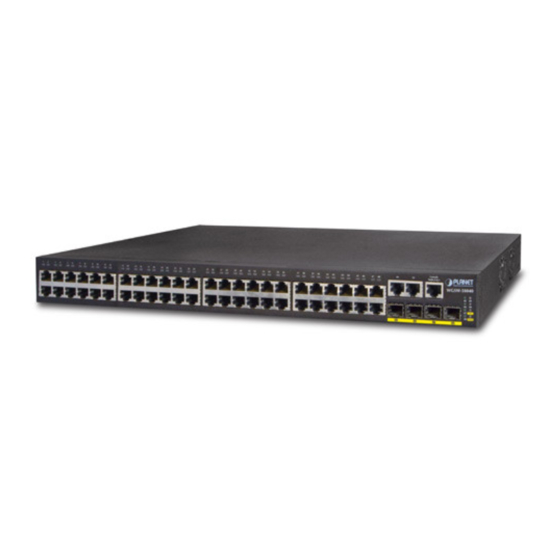
Figure 2-1 shows the front panel of the Managed Switch. WGSW-50040 Front Panel Figure 2-1 WGSW-50040 front panel ■ Gigabit TP interface 10/100/1000Base-T Copper, RJ-45 Twist-Pair: Up to 100 meters. ■ Gigabit SFP slots 1000Base-SX/LX mini-GBIC slot, SFP (Small Form Factor Pluggable) transceiver module: From 550 meters (Multi-mode fiber), up to 10/20/30/40/50/70/120 kilometers (Single-mode fiber). -
Page 19: Led Indications
2.1.2 LED Indications The front panel LEDs indicates instant status of port links, data activity, system operation, Stack status and system power, helps monitor and troubleshoot when needed. WGSW-50040 LED indication Figure 2-2 WGSW-50040 LED panel ■ System Color Function Green Lights to indicate that the Switch has power. -
Page 20: Switch Rear Panel
Figure 2-3 shows the rear panel of these Managed Switch. WGSW-50040 Rear Panel Figure 2-3 Rear panel of WGSW-50040 ■ AC Power Receptacle For compatibility with electric service in most areas of the world, the Managed Switch’s power supply automatically adjusts to line power in the range 100-240VAC and 50/60 Hz. -
Page 21: Install The Switch
2.2 Install the Switch This section describes how to install your Managed Switch and make connections to the Managed Switch. Please read the following topics and perform the procedures in the order being presented. To install your Managed Switch on a desktop or shelf, simply complete the following steps. 2.2.1 Desktop Installation To install the Managed Switch on desktop or shelf, please follows these steps: Step1: Attach the rubber feet to the recessed areas on the bottom of the Managed Switch. -
Page 22: Rack Mounting
Figure 2-6. Figure 2-6 Mounting WGSW-50040 in a Rack Step6: Proceeds with the steps 4 and steps 5 of session 2.2.1 Desktop Installation to connect the network cabling and supply power to the Managed Switch. -
Page 23: Installing The Sfp Transceiver
2.2.3 Installing the SFP transceiver The sections describe how to insert an SFP transceiver into an SFP slot. The SFP transceivers are hot-pluggable and hot-swappable. You can plug-in and out the transceiver to/from any SFP port without having to power down the Managed Switch. As the Figure 2-7 appears. - Page 24 be male duplex LC connector type. Connect the fiber cable Attach the duplex LC connector on the network cable into the SFP transceiver. Connect the other end of the cable to a device – switches with SFP installed, fiber NIC on a workstation or a Media Converter.
-
Page 25: Chapter 3 Switch Management
Chapter 3 Switch Management 3.1 Management Options After purchasing the switch, the user needs to configure the switch for network management. Switch provides two management options: in-band management and out-of-band management. 3.1.1 Out-Of-Band Management Out-of-band management is the management through Console interface. Generally, the user will use out-of-band management for the initial switch configuration, or when in-band management is not available. - Page 26 Figure 3-2 Opening Hyper Terminal 2) Type a name for opening HyperTerminal, such as “Switch”. Figure 3-3 Opening HyperTerminal...
- Page 27 3) In the “Connecting using” drop-list, select the RS-232 serial port used by the PC, e.g. COM1, and click “OK”. Figure 3-4 Opening HyperTerminal 4) COM1 property appears, select “9600” for “Baud rate”, “8” for “Data bits”, “none” for “Parity checksum”, “1” for stop bit and “none”...
-
Page 28: In-Band Management
Step 3: Entering switch CLI interface Power on the switch, the following appears in the HyperTerminal windows, that is the CLI configuration mode for Switch. Testing RAM... 0x077C0000 RAM OK Loading MiniBootROM... Attaching to file system ... Loading nos.img ... done. Booting.. - Page 29 The switch is Layer 3 switch that can be configured with several IPv4/IPv6 addresses. The following example assumes the shipment status of the switch where only VLAN1 exists in the system. The following describes the steps for a Telnet client to connect to the switch’s VLAN1 interface by Telnet (with IPv4 address example): Figure 3-6 Manage the switch by Telnet Step 1: Configure the IP addresses for the switch and start the Telnet Server function on the switch.
- Page 30 Step 2: Run Telnet Client program. Run Telnet client program included in Windows with the specified Telnet target. Figure 3-7 Run telnet client program included in Windows Step 3: Login to the switch. Login to the Telnet configuration interface. Valid login name and password are required, otherwise the switch will reject Telnet access.
-
Page 31: Management Via Http
3.1.2.2 Management via HTTP To manage the switch via HTTP, the following conditions should be met: Switch has an IPv4/IPv6 address configured; The host IPv4/IPv6 address (HTTP client) and the switch’s VLAN interface IPv4/IPv6 address are in the same network segment; If 2) is not met, HTTP client should connect to an IPv4/IPv6 address of the switch via other devices, such as a router. - Page 32 “admin”, and password of “admin”, the configuration procedure should like the following: Switch>enable Switch#config Switch(config)#username admin privilege 15 password 0 admin Switch(config)#authentication line web login local The Web login interface of WGSW-50040 is as below: Figure 3-10 Web Login Interface 3-15...
-
Page 33: Cli Interface
Input the right username and password, and then the main Web configuration interface is shown as below. Figure 3-11 Main Web Configuration Interface When configure the switch, the name of the switch is composed with English letters. 3.1.2.3 Manage the Switch via SNMP Network Management Software The necessities required by SNMP network management software to manage switches: 1) IP addresses are configured on the switch;... -
Page 34: Configuration Modes
CLI interface is familiar to most users. As aforementioned, out-of-band management and Telnet login are all performed through CLI interface to manage the switch. CLI Interface is supported by Shell program, which consists of a set of configuration commands. Those commands are categorized according to their functions in switch configuration and management. -
Page 35: Admin Mode
3.2.1.2 Admin Mode To Admin Mode sees the following: In user entry system, if as Admin user, it is defaulted to Admin Mode. Admin Mode prompt “Switch#” can be entered under the User Mode by running the enable command and entering corresponding access levels admin user password, if a password has been set. -
Page 36: Configuration Syntax
Type the ip dhcp pool <name> command under Global Mode will enter the DHCP Address Pool Mode prompt “Switch(Config-<name>-dhcp)#”. DHCP address pool properties can be configured under DHCP Address Pool Mode. Run the exit command to exit the DHCP Address Pool Mode to Global Mode. ... -
Page 37: Help Function
commands can be shown. Down “↓” Show next command entered. When use the Up key to get previously entered commands, you can use the Down key to return to the next command Left “←” The cursor moves one character to You can use the Left and the left. -
Page 38: Fuzzy Match Support
Returned Information: error Output error message Explanation Unrecognized command or illegal The entered command does not exist, or there is parameter! error in parameter scope, type or format. Ambiguous command At least two interpretations is possible basing on the current input. Invalid command or parameter The command is recognized, but no valid parameter record is found. -
Page 39: Chapter 4 Basic Switch Configuration
Chapter 4 Basic Switch Configuration 4.1 Basic Configuration Basic switch configuration includes commands for entering and exiting the admin mode, commands for entering and exiting interface mode, for configuring and displaying the switch clock, for displaying the version information of the switch system, etc. Command Explanation Normal User Mode/ Admin Mode... -
Page 40: Telnet Management
4.2 Telnet Management 4.2.1 Telnet 4.2.1.1 Introduction to Telnet Telnet is a simple remote terminal protocol for remote login. Using Telnet, the user can login to a remote host with its IP address of hostname from his own workstation. Telnet can send the user’s keystrokes to the remote host and send the remote host output to the user’s screen through TCP connection. -
Page 41: Ssh
authentication ip access-class Binding standard IP ACL protocol to login with {<num-std>|<name>} Telnet/SSH/Web; the no form command will no authentication ip access-class cancel the binding ACL. authentication ipv6 access-class Binding standard IPv6 ACL protocol to login with {<num-std>|<name>} Telnet/SSH/Web; the no form command will no authentication ipv6 access-class cancel the binding ACL. - Page 42 4.2.2.2 SSH Server Configuration Task List SSH Server Configuration Command Explanation Global Mode Enable SSH function on the switch; the “no ssh-server enable ssh-server enable” command disables SSH no ssh-server enable function. Configure the username and password of SSH ssh-user <user-name> password {0 | 7} client software for logging on the switch;...
-
Page 43: Configurate Switch Ip Addresses
Switch(Config-if-Vlan1)#exit Switch(config)# username test privilege 15 password 0 test In IPv6 networks, the terminal should run IPv6-supporing SSH client software, such as putty6. Users should make no modification to configurations on the switch except allocating an IPv6 address for the local host. 4.3 Configurate Switch IP Addresses All Ethernet ports of switch are default to Data Link layer ports and perform layer 2 forwarding. -
Page 44: Snmp Configuration
ip address <ip_address> <mask> Configure the VLAN interface IP address; the “no [secondary] ip address <ip_address> <mask> [secondary]” no ip address <ip_address> <mask> command deletes VLAN interface IP address. [secondary] ipv6 address <ipv6-address / Configure IPv6 address, including aggregation global prefix-length>... -
Page 45: Introduction To Mib
Management Station) and Agent. NMS is the workstation on which SNMP client program is running. It is the core on the SNMP network management. Agent is the server software runs on the devices which need to be managed. NMS manages all the managed objects through Agents. The switch supports Agent function. The communication between NMS and Agent functions in Client/Server mode by exchanging standard messages. -
Page 46: Introduction To Rmon
Figure 4-1 ASN.1 Tree Instance In this figure, the OID of the object A is 1.2.1.1. NMS can locate this object through this unique OID and gets the standard variables of the object. MIB defines a set of standard variables for monitored network devices by following this structure. -
Page 47: Snmp Configuration
Event: A list of all events generated by RMON Agent. Alarm depends on the implementation of Event. Statistics and History display some current or history subnet statistics. Alarm and Event provide a method to monitor any integer data change in the network, and provide some alerts upon abnormal events (sending Trap or record in logs). - Page 48 3. Configure IP address of SNMP management base Command Explanation Global Mode snmp-server securityip { <ipv4-addr> | Configure the secure IPv4/IPv6 address which is <ipv6-addr> } allowed to access the switch on the NMS; the no no snmp-server securityip { <ipv4-addr> | command deletes configured secure address.
-
Page 49: Typical Snmp Configuration Examples
{<ipv6-num-std>|<ipv6-name>}] 7. Configure view Command Explanation Global Mode snmp-server view <view-string> <oid-string> {include|exclude} Configure view on the switch. This command is used no snmp-server view for SNMP v3. <view-string>[<oid-string>] 8. Configuring TRAP Command Explanation Global Mode snmp-server enable traps Enable the switch to send Trap message. This no snmp-server enable traps command is used for SNMP v1/v2/v3. - Page 50 The NMS can use private as the community string to access the switch with read-write permission, or use public as the community string to access the switch with read-only permission. Scenario 2: NMS will receive Trap messages from the switch (Note: NMS may have community string verification for the Trap messages.
-
Page 51: Snmp Troubleshooting
Switch(config)#snmp-server host 2004:1:2:3::2 v1 trap Switch(config)#snmp-server enable traps 4.4.6 SNMP Troubleshooting When users configure the SNMP, the SNMP server may fail to run properly due to physical connection failure and wrong configuration, etc. Users can troubleshoot the problems by following the guide below: ... -
Page 52: Bootrom Upgrade
will be explained in details in following two sections. 4.5.2 BootROM Upgrade There are two methods for BootROM upgrade: TFTP and FTP, which can be selected at BootROM command settings. cable Console cable connection connection Figure 4-2 Typical topology for switch upgrade in BootROM mode The upgrade procedures are listed below: Step 1: As shown in the figure, a PC is used as the console for the switch. - Page 53 [Boot] Step 4: Enable FTP/TFTP server in the PC. For TFTP, run TFTP server program; for FTP, run FTP server program. Before start downloading upgrade file to the switch, verify the connectivity between the server and the switch by ping from the server. If ping succeeds, run “load” command in the BootROM mode from the switch; if it fails, perform troubleshooting to find out the cause.
-
Page 54: Ftp/Tftp Upgrade
Step 8: After successful upgrade, execute run or reboot command in BootROM mode to return to CLI configuration interface. [Boot]: run(or reboot) Other commands in BootROM mode 1. DIR command Used to list existing files in the FLASH . [Boot]: dir boot.rom 327,440 1900-01-01 00:00:00 --SH boot.conf... - Page 55 management connection maintains until data transfer is complete. Then, using the address and port number provided by the client, the server establishes data connection on port 20 (if not engaged) to transfer data; if port 20 is engaged, the server automatically generates some other port number to establish data connection. In passive connection, the client, through management connection, notify the server to establish a passive connection.
- Page 56 Running configuration file: refers to the running configuration sequence use in the switch. In switch, the running configuration file stores in the RAM. In the current version, the running configuration sequence running-config can be saved from the RAM to FLASH by write command or copy running-config startup-config command, so that the running configuration sequence becomes the start up configuration file, which is called configuration save.
- Page 57 For FTP client, server file list can be ftp-dir <ftpServerUrl> checked. FtpServerUrl format looks like: ftp: //user: password@IPv4|IPv6 Address. 2. FTP server configuration (1)Start FTP server Command Explanation Global Mode Start FTP server and support IPv4, IPv6, the no ftp-server enable command shuts down FTP server and prevents no ftp-server enable FTP user from logging in.
- Page 58 Global Mode tftp-server retransmission-timeout Set maximum retransmission time within timeout <seconds> interval. (3)Modify TFTP server connection retransmission time Command Explanation Global Mode tftp-server retransmission-number Set the retransmission time for TFTP server. <number> 4.5.3.3 FTP/TFTP Configuration Examples It is the same configuration switch for IPv4 addresses and IPv6 addresses. The example only for the IPv4 addresses configuration.
- Page 59 Switch(config)#exit Switch#copy ftp: //Switch:switch@10.1.1.1/12_30_nos.img nos.img With the above commands, the switch will have the “nos.img” file in the computer downloaded to the FLASH. TFTP Configuration Computer side configuration: Start TFTP server software on the computer and place the “nos.img” file to the appropriate TFTP server directory on the computer.
- Page 60 Computer side configuration: Login to the switch with any TFTP client software, use the “tftp” command to download “nos.img” file from the switch to the computer. Scenario 4: Switch acts as FTP client to view file list on the FTP server. Synchronization conditions: The switch connects to a computer by an Ethernet port, the computer is a FTP server with an IP address of 10.1.1.1;...
- Page 61 4.5.3.4.1 FTP Troubleshooting When upload/download system file with FTP protocol, the connectivity of the link must be ensured, i.e., use the “Ping” command to verify the connectivity between the FTP client and server before running the FTP program. If ping fails, you will need to check for appropriate troubleshooting information to recover the link connectivity.
- Page 62 When upload/download system file with TFTP protocol, the connectivity of the link must be ensured, i.e., use the “Ping” command to verify the connectivity between the TFTP client and server before running the TFTP program. If ping fails, you will need to check for appropriate troubleshooting information to recover the link connectivity.
-
Page 63: Chapter 5 Cluster Configuration
Chapter 5 Cluster Configuration 5.1 Introduction to cluster network management Cluster network management is an in-band configuration management. Unlike CLI, SNMP and Web Config which implement a direct management of the target switches through a management workstation, cluster network management implements a direct management of the target switches (member switches) through an intermediate switch (commander switch). - Page 64 5) Clear the list of candidate switches maintained by the switch 4. Configure attributes of the cluster in the candidate switch 1) Set the time interval of keep-alive messages of the cluster 2) Set the max number of lost keep-alive messages that can be tolerated in the cluster 5....
- Page 65 number lost cluster keepalive loss-count <int> keep-alive messages that can be no cluster keepalive loss-count tolerated in the cluster. Admin mode clear cluster nodes [nodes-sn Clear nodes in the list of candidate <candidate-sn-list> | mac-address switches maintained by the switch. <mac-addr>] 4.
- Page 66 6. Manage cluster network with web Command Explanation Global Mode Enable http function in commander switch and member switch. Notice: must insure the http function be enabled in member switch when ip http server commander switch visiting member switch by web. The commander switch visit member switch via beat member node in member cluster topology.
-
Page 67: Examples Of Cluster Administration
5.3 Examples of Cluster Administration Scenario: The four switches SW1-SW4, amongst the SW1 is the command switch and other switches are member switch. The SW2 and SW4 is directly connected with the command switch, SW3 connects to the command switch through SW2. Figure 5-1 Examples of Cluster Configuration Procedure Configure the command switch... -
Page 68: Chapter 6 Port Configuration
Chapter 6 Port Configuration 6.1 Introduction to Port Switch contain Cable ports and Combo ports. The Combo ports can be configured to as either 1000GX-TX ports or SFP Gigabit fiber ports. If the user needs to configure some network ports, he/she can use the interface ethernet <interface-list> command to enter the appropriate Ethernet port configuration mode, where <interface-list>... -
Page 69: Port Configuration Example
shutdown Enables/Disables specified ports. no shutdown name <string> Names or cancels the name of specified ports. no name Sets the cable type for the specified port; this mdi {auto | across | normal} command is not supported by combo port and no mdi fiber port of switch. -
Page 70: Port Troubleshooting
Figure 6-1 Port Configuration Example No VLAN has been configured in the switches, default VLAN1 is used. Switch Port Property Switch1 Ingress bandwidth limit: 150 M Switch2 Mirror source port 100Mbps full, mirror source port 1/10 1000Mbps full, mirror destination port Switch3 1/12 100Mbps full... -
Page 71: Chapter 7 Port Loopback Detection Function Configuration
Chapter 7 Port Loopback Detection Function Configuration 7.1 Introduction to Port Loopback Detection Function With the development of switches, more and more users begin to access the network through Ethernet switches. In enterprise network, users access the network through layer-2 switches, which means urgent demands for both internet and the internal layer 2 Interworking. - Page 72 loopback-detection interval-time Configure the time interval of loopback <loopback> <no-loopback> detection. no loopback-detection interval-time 2. Enable the function of port loopback detection Command Explanation Global Mode loopback-detection specified-vlan <vlan-list> Enable and disable the function of port no loopback-detection specified-vlan loopback detection. <vlan-list>...
-
Page 73: Port Loopback Detection Function Example
7.3 Port Loopback Detection Function Example SWITCH Network Topology Figure 7-1 A typical example of port loopback detection As shown in the above configuration, the switch will detect the existence of loopbacks in the network topology. After enabling the function of loopback detection on the port connecting the switch with the outside network, the switch will notify the connected network about the existence of a loopback, and control the port on the switch to guarantee the normal operation of the whole network. -
Page 74: Chapter 8 Port Channel Configuration
Chapter 8 Port Channel Configuration 8.1 Introduction to Port Channel To understand Port Channel, Port Group should be introduced first. Port Group is a group of physical ports in the configuration level; only physical ports in the Port Group can take part in link aggregation and become a member port of a Port Channel. -
Page 75: Port Channel Configuration Task List
the same. If Port Channel is configured manually or dynamically on switch, the system will automatically set the port with the smallest number to be Master Port of the Port Channel. If the spanning tree function is enabled in the switch, the spanning tree protocol will regard Port Channel as a logical port and send BPDU frames via the master port. -
Page 76: Port Channel Examples
<port-channel-number> 8.3 Port Channel Examples Scenario 1: Configuring Port Channel in LACP. SwitchA SwitchB Figure 8-2 Configuring Port Channel in LACP The switches in the description below are all switch and as shown in the figure, ports 1, 2, 3, 4 of SwitchA are access ports that belong to VLAN1. - Page 77 Configuration result: Shell prompts ports aggregated successfully after a while, now ports 1, 2, 3, 4 of Switch A form an aggregated port named “Port-Channel1”, ports 6, 8, 9, 10 of Switch B forms an aggregated port named “Port-Channel2”; configurations can be made in their respective aggregated port configuration mode. Scenario 2: Configuring Port Channel in ON mode.
-
Page 78: Port Channel Troubleshooting
SwitchB (Config-If-Port-Range)#exit Configuration result: Add ports 1, 2, 3, 4 of Switch 1 to port-group 1 in order, and we can see a group in “on” mode is completely joined forcedly, switch in other ends won’t exchange LACP BPDU to complete aggregation. Aggregation finishes immediately when the command to add port 2 to port-group 1 is entered, port 1 and port 2 aggregate to be port-channel 1, when port 3 joins port-group 1, port-channel 1 of port 1 and 2 are ungrouped and re-aggregate with port 3 to form port-channel 1, when port 4 joins port-group 1, port-channel 1 of port 1, 2 and... -
Page 79: Chapter 9 Jumbo Configuration
Chapter 9 Jumbo Configuration 9.1 Introduction to Jumbo So far the Jumbo (Jumbo Frame) has not reach a determined standard in the industry (including the format and length of the frame). Normally frames sized within 1519-9000 should be considered jumbo frame. Networks with jumbo frames will increase the speed of the whole network by 2% to 5%. -
Page 80: Chapter 10 Vlan Configuration
Chapter 10 VLAN Configuration 10.1 VLAN Configuration 10.1.1 Introduction to VLAN VLAN (Virtual Local Area Network) is a technology that divides the logical addresses of devices within the network to separate network segments basing on functions, applications or management requirements. By this way, virtual workgroups can be formed regardless of the physical location of the devices. -
Page 81: Vlan Configuration Task List
The switch implements VLAN and GVRP (GARP VLAN Registration Protocol) which are defined by 802.1Q. The chapter will explain the use and the configuration of VLAN and GVRP in detail. 10.1.2 VLAN Configuration Task List 1. Create or delete VLAN 2. - Page 82 5. Set Trunk port Command Explanation Port Mode switchport trunk allowed vlan {WORD | all Set/delete VLAN allowed to be crossed | add WORD | except WORD|remove by Trunk. The “no” command restores WORD} the default setting. no switchport trunk allowed vlan switchport trunk native vlan <vlan-id>...
-
Page 83: Typical Vlan Application
10.1.3 Typical VLAN Application Scenario: VLAN100 VLAN2 VLAN200 Workstation Workstation Switch A Trunk Link Switch B VLAN2 VLAN200 Workstation VLAN100 Workstation Figure 10-2 Typical VLAN Application Topology The existing LAN is required to be partitioned to 3 VLANs due to security and application requirements. The three VLANs are VLAN2, VLAN100 and VLAN200. -
Page 84: Gvrp Configuration
Switch(Config-Vlan100)#exit Switch(config)#vlan 200 Switch(Config-Vlan200)#switchport interface ethernet 1/8-10 Switch(Config-Vlan200)#exit Switch(config)#interface ethernet 1/11 Switch(Config-If-Ethernet1/11)#switchport mode trunk Switch(Config-If-Ethernet1/11)#exit Switch(config)# Switch B: Switch(config)#vlan 2 Switch(Config-Vlan2)#switchport interface ethernet 1/2-4 Switch(Config-Vlan2)#exit Switch(config)#vlan 100 Switch(Config-Vlan100)#switchport interface ethernet 1/5-7 Switch(Config-Vlan100)#exit Switch(config)#vlan 200 Switch(Config-Vlan200)#switchport interface ethernet 1/8-10 Switch(Config-Vlan200)#exit Switch(config)#interface ethernet 1/11 Switch(Config-If-Ethernet1/11)#switchport mode trunk Switch(Config-If-Ethernet1/11)#exit 10.2 GVRP Configuration... -
Page 85: Gvrp Configuration Task List
10.2.2 GVRP Configuration Task List 1. Configuring GARP Timer parameters Command Explanation Port Mode garp timer join <timer-value> no garp timer join garp timer leave <timer-value> Configure the hold, join and no garp timer leave leave timers for GARP. garp timer hold <timer-value> no garp timer hold Global Mode garp timer leaveall <timer-value>... -
Page 86: Typical Gvrp Application
10.2.3 Typical GVRP Application Scenario: Switch A Switch B Switch C Figure 10-3 Typical GVRP Application Topology To enable dynamic VLAN information register and update among switches, GVRP protocol is to be configured in the switch. Configure GVRP in Switch A, B and C, enable Switch B to learn VLAN100 dynamically so that the two workstation connected to VLAN100 in Switch A and C can communicate with each other through Switch B without static VLAN100 entries. -
Page 87: Gvrp Troubleshooting
Switch(Config-Vlan100)#exit Switch(config)#interface Ethernet 1/11 Switch(Config-If-Ethernet1/11)#switchport mode trunk Switch(Config-If-Ethernet1/11)# gvrp Switch(Config-If-Ethernet1/11)#exit Switch B: Switch(config)# bridge-ext gvrp Switch(config)#interface ethernet 1/10 Switch(Config-If-Ethernet1/10)#switchport mode trunk Switch(Config-If-Ethernet1/10)# gvrp Switch(Config-If-Ethernet1/10)#exit Switch(config)#interface ethernet 1/11 Switch(Config-If-Ethernet1/11)#switchport mode trunk Switch(Config-If-Ethernet1/11)# gvrp Switch(Config-If-Ethernet1/11)#exit Switch C: Switch(config)# gvrp Switch(config)#vlan 100 Switch(Config-Vlan100)#switchport interface ethernet 1/2-6 Switch(Config-Vlan100)#exit Switch(config)#interface ethernet 1/11 Switch(Config-If-Ethernet1/11)#switchport mode trunk... -
Page 88: Dot1Q-Tunnel Configuration
as backbone equipment. On the customer port Trunk VLAN 200-300 This port on PE1 is enabled Unsymmetrical QinQ and belong to VLAN3 connection SP networks Customer Trunk connection networks1 Trunk connection This port on PE1 is enabled QinQ and belong to VLAN3 Unsymmetrical Customer connection... -
Page 89: Typical Applications Of The Dot1Q-Tunnel
1. Configure the dot1q-tunnel function on the ports Command Explanation Port mode dot1q-tunnel enable Enter/exit the dot1q-tunnel mode on the no dot1q-tunnel enable ports. 2. Configure the type of protocol (TPID) on the ports Command Explanation Port mode dot1q-tunnel tpid Configure the type of protocol on port. -
Page 90: Dot1Q-Tunnel Troubleshooting
PE2: Switch(config)#vlan 3 Switch(Config-Vlan3)#switchport interface ethernet 1/1 Switch(Config-Vlan3)#exit Switch(Config)#interface ethernet 1/1 Switch(Config-Ethernet1/1)# dot1q-tunnel enable Switch(Config-Ethernet1/1)# exit Switch(config)#interface ethernet 1/10 Switch(Config-Ethernet1/10)#switchport mode trunk switch(Config-Ethernet1/10)#dot1q-tunnel tpid 0x9100 Switch(Config-Ethernet1/10)#exit Switch(Config)# 10.3.4 Dot1q-tunnel Troubleshooting Enabling dot1q-tunnel on Trunk port will make the tag of the data packet unpredictable which is not required in the application. -
Page 91: Dynamic Vlan Configuration
no need of added frame label to identify the VLAN which reduce the network traffic. 10.4.2 Dynamic VLAN Configuration Dynamic VLAN Configuration Task Sequence: Configure the MAC-based VLAN function on the port Set the VLAN to MAC VLAN Configure the correspondence between the MAC address and the VLAN Configure the IP-subnet-based VLAN function on the port Configure the correspondence between the IP subnet and the VLAN Configure the correspondence between the Protocols and the VLAN... - Page 92 5. Configure the correspondence between the IP subnet and the VLAN Command Explanation Global Mode subnet-vlan ip-address <ipv4-addrss> Add/delete the correspondence between mask <subnet-mask> vlan <vlan-id> the IP subnet and the VLAN, namely priority <priority-id> specified IP subnet joins/leaves specified no subnet-vlan {ip-address <ipv4-addrss>...
-
Page 93: Typical Application Of The Dynamic Vlan
10.4.3 Typical Application of the Dynamic VLAN Scenario: In the office network Department A belongs to VLAN100. Several members of this department often have the need to move within the whole office network. It is also required to ensure the resource for other members of the department to access VLAN 100. -
Page 94: Dynamic Vlan Troubleshooting
10.4.4 Dynamic VLAN Troubleshooting On the switch configured with dynamic VLAN, if the two connected equipment (e.g. PC) are both belongs to the same dynamic VLAN, first communication between the two equipment may not go through. The solution will be letting the two equipment positively send data packet to the switch (such as ping), to let the switch learn their source MAC, then the two equipment will be able to communicate freely within the dynamic VLAN. -
Page 95: Voice Vlan Configuration
10.5.2 Voice VLAN Configuration Voice VLAN Configuration Task Sequence: Set the VLAN to Voice VLAN Add a voice equipment to Voice VLAN Enable the Voice VLAN on the port 1. Configure the VLAN to Voice VLAN Command Explanation Global Mode voice-vlan vlan <vlan-id>... -
Page 96: Voice Vlan Troubleshooting
Switch IP-phone1 IP-phone2 Figure 10-7 VLAN typical apply topology Configuration items Configuration Explanation Voice VLAN Global configuration on the Switch. Configuration procedure: Switch 1: Switch(config)#vlan 100 Switch(Config-Vlan100)#exit Switch(config)#voice-vlan vlan 100 Switch(config)#voice-vlan mac 00-30-4f-11-22-33 mask 255 priority 5 name company Switch(config)#voice-vlan mac 00-30-4f-11-22-55 mask 255 priority 5 name company Switch(config)#interface ethernet 1/10 Switch(Config-If-Ethernet1/10)#switchport mode trunk Switch(Config-If-Ethernet1/10)#exit... -
Page 97: Chapter 11 Mac Table Configuration
Chapter 11 MAC Table Configuration 11.1 Introduction to MAC Table MAC table is a table identifies the mapping relationship between destination MAC addresses and switch ports. MAC addresses can be categorized as static MAC addresses and dynamic MAC addresses. Static MAC addresses are manually configured by the user, have the highest priority and are permanently effective (will not be overwritten by dynamic MAC addresses);... - Page 98 Port 5 Port 12 MAC 00-01-11-11-11-11 MAC 00-01-33-33-33-33 MAC 00-01-22-22-22-22 MAC 00 01 44 44 44 44 Figure 11-1 MAC Table dynamic learning The topology of the figure above: 4 PCs connected to switch, where PC1 and PC2 belongs to a same physical segment (same collision domain), the physical segment connects to port 1/5 of switch;...
-
Page 99: Forward Or Filter
11.1.2 Forward or Filter The switch will forward or filter received data frames according to the MAC table. Take the above figure as an example, assuming switch have learnt the MAC address of PC1 and PC3, and the user manually configured the mapping relationship for PC2 and PC4 to ports. -
Page 100: Typical Configuration Examples
Configure the MAC aging-time Command Explanation Global Mode mac-address-table aging-time Configure the MAC address aging-time. <0|aging-time> no mac-address-table aging-time Configure static MAC forwarding or filter entry Command Explanation Global Mode mac-address-table {static | blackhole} address <mac-addr> vlan <vlan-id > [interface [ethernet | portchannel] <interface-name>] | Configure static MAC forwarding or filter [source|destination|both]... -
Page 101: Mac Table Troubleshooting
to the default VLAN1. As required by the network environment, dynamic learning is enabled. PC1 holds sensitive data and can not be accessed by any other PC that is in another physical segment; PC2 and PC3 have static mapping set to port 7 and port 9, respectively. The configuration steps are listed below: Set the MAC address 00-01-11-11-11-11 of PC1 as a filter address. - Page 102 11.5.1.2 MAC Address Binding Configuration Task List Enable MAC address binding function for the ports Lock the MAC addresses for a port MAC address binding property configuration Enable MAC address binding function for the ports Command Explanation Port Mode Enable MAC address binding function for the port and lock the port.
- Page 103 MAC address binding property configuration Command Explanation Port Mode switchport port-security maximum Set the maximum number of secure MAC <value> addresses for a port; the “no switchport no switchport port-security maximum port-security maximum” command <value> restores the default value. switchport port-security violation Set the violation mode for the port;...
-
Page 104: Chapter 12 Mstp Configuration
Chapter 12 MSTP Configuration 12.1 Introduction to MSTP The MSTP (Multiple STP) is a new spanning-tree protocol which is based on the STP and the RSTP. It runs on all the bridges of a bridged-LAN. It calculates a common and internal spanning tree (CIST) for the bridge-LAN which consists of the bridges running the MSTP, the RSTP and the STP. -
Page 105: Operations Within An Mstp Region
Root Root REGION Figure 12-1 Example of CIST and MST Region In the above network, if the bridges are running the STP or the RSTP, one port between Bridge M and Bridge B should be blocked. But if the bridges in the yellow range run the MSTP and are configured in the same MST region, MSTP will treat this region as a bridge. -
Page 106: Port Roles
12.1.2 Port Roles The MSTP bridge assigns a port role to each port which runs MSTP. CIST port roles: Root Port, Designated Port, Alternate Port and Backup Port On top of those roles, each MSTI port has one new role: Master Port. The port roles in the CIST (Root Port, Designated Port, Alternate Port and Backup Port) are defined in the same ways as those in the RSTP. - Page 107 2. Configure instance parameters Command Explanation Global Mode spanning-tree mst <instance-id> priority <bridge-priority> Set bridge priority for specified instance. no spanning-tree mst <instance-id> priority spanning-tree priority <bridge-priority> Configure the spanning-tree priority of the no spanning-tree priority switch. Port Mode spanning-tree mst <instance-id> cost <cost>...
- Page 108 4. Configure MSTP time parameters Command Explanation Global Mode spanning-tree forward-time <time> Set the value for switch forward delay no spanning-tree forward-time time. spanning-tree hello-time <time> Set the Hello time for sending BPDU no spanning-tree hello-time messages. spanning-tree maxage <time> Set Aging time for BPDU messages.
-
Page 109: Mstp Example
8. Configure the FLUSH mode once topology changes Command Explanation Global Mode Enable: the spanning-tree flush once the topology changes. Disable: the spanning tree don’t flush when the topology changes. spanning-tree tcflush {enable| disable| Protect: the spanning-tree flush not protect} more than time... - Page 110 Bridge Name Switch1 Switch2 Switch3 Switch4 Bridge MAC …00-00-01 …00-00-02 …00-00-03 …00-00-04 Address Bridge Priority 32768 32768 32768 32768 Port 1 Port 2 Port 3 Port 4 Port 5 Port 6 Port 7 Port 1 200000 200000 200000 Port 2 200000 200000 200000...
- Page 111 Switch2(Config-Vlan50)#exit Switch2(config)#spanning-tree mst configuration Switch2(Config-Mstp-Region)#name mstp Switch2(Config-Mstp-Region)#instance 3 vlan 20;30 Switch2(Config-Mstp-Region)#instance 4 vlan 40;50 Switch2(Config-Mstp-Region)#exit Switch2(config)#interface e1/1-7 Switch2(Config-Port-Range)#switchport mode trunk Switch2(Config-Port-Range)#exit Switch2(config)#spanning-tree Switch3: Switch3(config)#vlan 20 Switch3(Config-Vlan20)#exit Switch3(config)#vlan 30 Switch3(Config-Vlan30)#exit Switch3(config)#vlan 40 Switch3(Config-Vlan40)#exit Switch3(config)#vlan 50 Switch3(Config-Vlan50)#exit Switch3(config)#spanning-tree mst configuration Switch3(Config-Mstp-Region)#name mstp Switch3(Config-Mstp-Region)#instance 3 vlan 20;30 Switch3(Config-Mstp-Region)#instance 4 vlan 40;50 Switch3(Config-Mstp-Region)#exit...
- Page 112 Switch4(config)#interface e1/1-7 Switch4(Config-Port-Range)#switchport mode trunk Switch4(Config-Port-Range)#exit Switch4(config)#spanning-tree Switch4(config)#spanning-tree mst 4 priority 0 After the above configuration, Switch1 is the root bridge of the instance 0 of the entire network. In the MSTP region which Switch2, Switch3 and Switch4 belong to, Switch2 is the region root of the instance 0, Switch3 is the region root of the instance 3 and Switch4 is the region root of the instance 4.
-
Page 113: Mstp Troubleshooting
Figure 12-4 The Topology Of the Instance 3 after the MSTP Calculation Switch2 Switch3 Switch4 Figure 12-5 The Topology Of the Instance 4 after the MSTP Calculation 12.4 MSTP Troubleshooting In order to run the MSTP on the switch port, the MSTP has to be enabled globally. If the MSTP is not enabled globally, it can’t be enabled on the port. -
Page 114: Chapter 13 Qos Configuration
Chapter 13 QoS Configuration 13.1 Introduction to QoS QoS (Quality of Service) is a set of capabilities that allow you to create differentiated services for network traffic, thereby providing better service for selected network traffic. QoS is a guarantee for service quality of consistent and predictable data transfer service to fulfill program requirements. -
Page 115: Qos Implementation
A field of the MPLS packets means the service class, there are 3 bits, the ranging from 0 to 7. Internal Priority: The internal priority setting of the switch chip, it’s valid range relates with the chip, it’s shortening is Int-Prio or IntP。 Drop Precedence: When processing the packets, firstly drop the packets with the bigger drop precedence, the ranging is 0-2 in three color algorithm, the ranging is 0-1 in dual color algorithm. - Page 116 Figure 13-3 Basic QoS Model Classification: Classify traffic according to packet classification information and generate internal priority and drop precedence based the classification information. For different packet types and switch configurations, classification is performed differently; the flowchart below explains this in detail. 13-3...
- Page 117 Figure 13-4 Classification process Policing and remark: Each packet in classified ingress traffic is assigned an internal DSCP value and can be policed and remarked. Policing can be performed based on the flow to configure different policies that allocate bandwidth to classified traffic, the assigned bandwidth policy may be dual bucket dual color or dual bucket three color.
- Page 118 Check policing policy, is traffic in-profile? Figure 13-5 Policing and Remarking process Queuing and scheduling: There are the internal priority and the drop precedence for the egress packets, the queuing operation assigns the packets to different priority queues according to the internal priority, while the scheduling operation perform the packet forwarding according to the priority queue weight and the drop precedence.
-
Page 119: Qos Configuration Task List
Figure 13-6 Queuing and Scheduling process 13.2 QoS Configuration Task List 1. Configure class map. Set up a classification rule according to ACL, CoS, VLAN ID, IPv4 Precedent, DSCP, IPV6 FL to classify the data stream. Different classes of data streams will be processed with different policies. 2.... - Page 120 3. Apply QoS to the ports or the VLAN interface Configure the trust mode for ports or bind policies to ports. A policy will only take effect on a port when it is bound to that port. The policy may be bound to the specific VLAN. 4....
- Page 121 no set {ip dscp | ip precedence|internal priority | drop precedence |cos } Configure a policy for the classified flow. Single bucket mode: The non-aggregation policy command policy <bits_per_second> supports three colors. Analyze the <normal_burst_bytes> ({conform-action working mode of the token bucket, ACTION}| exceed-action ACTION} ) whether it is singe rate single bucket, Dual bucket mode:...
- Page 122 port. Configure the default CoS value of the mls qos cos {<default-cos>} port; the no command restores the no mls qos cos default setting. Apply a policy map to the specified port; the no command deletes the specified service-policy input <policy-map-name> policy map applied to the port.
-
Page 123: Qos Example
mls qos map intp-dscp <dscp1..dscp8> no mls qos map intp-dscp 6. Clear accounting data of the specific ports or VLANs Command Explanation Interface Mode Clear accounting data of the specified clear mls qos statistics [interface ports or VLAN Policy Map. If there are no <interface-name>... - Page 124 the incoming packet has no CoS value, it is default to 5 and will be put in queue6. All passing packets would not have their DSCP values changed. Example 2: In port ethernet1/2, set the bandwidth for packets from segment 192.168.1.0 to 10 Mb/s, with a burst value of 4 MB, all packets exceed this bandwidth setting will be dropped.
-
Page 125: Qos Troubleshooting
As shown in the figure, inside the block is a QoS domain, Switch1 classifies different traffics and assigns different IP precedences. For example, set CoS precedence for packets from segment 192.168.1.0 to 5 on port ethernet1/1. The port connecting to switch2 is a trunk port. In Switch2, set port ethernet 1/1 that connecting to swtich1 to trust CoS precedence. -
Page 126: Chapter 14 Flow-Based Redirection
Chapter 14 Flow-based Redirection 14.1 Introduction to Flow-based Redirection Flow-based redirection function enables the switch to transmit the data frames meeting some special condition (specified by ACL) to another specified port. The fames meeting a same special condition are called a class of flow, the ingress port of the data frame is called the source port of redirection, and the specified egress port is called the destination port of redirection. -
Page 127: Flow-Based Redirection Examples
14.3 Flow-based Redirection Examples Example: User’s request of configuration is listed as follows: redirecting the frames whose source IP is 192.168.1.111 received from port 1 to port 6, that is sending the frames whose source IP is 192.168.1.111 received from port 1 through port6. -
Page 128: Chapter 15 Layer 3 Management Configuration
Chapter 15 Layer 3 Management Configuration Switch only support Layer 2 forwarding, but can configure a Layer 3 management port for the communication of all kinds of management protocols based on the IP protocol. 15.1 Layer 3 Management Interface 15.1.1 Introduction to Layer 3 Management Interface Only one layer 3 management interface can be created on switch. -
Page 129: Ip Configuration
15.2 IP Configuration 15.2.1 IP Configuration Layer 3 interface can be configured as IPv4 interface, IPv6 interface. 15.2.1.1 IPv4 Address Configuration IPv4 address configuration task list: 1.Configure the IPv4 address of three-layer interface 1. Configure the IPv4 address of three-layer interface Command Explanation VLAN Interface Configuration Mode... - Page 130 ipv6 address Configure IPv6 address, including aggregatable global unicast addresses, site-local addresses <ipv6-address/prefix-length> and link-local addresses. The no ipv6 address [eui-64] <ipv6-address/prefix-length> command no ipv6 address cancels IPv6 address. <ipv6-address/prefix-length> (2) Configure default gateway Command Explanation Interface Configuration Mode ipv6 default-gateway Configure the default IPv6 gateway address;...
- Page 131 Configure Router advertisement Lifespan. The ipv6 nd ra-lifetime <seconds> NO command resumes default value (1800 no ipv6 nd ra-lifetime seconds). (5) Configure router advertisement Minimum Interval Command Description Interface Configuration Mode Configure the minimum interval for router ipv6 nd min-ra-interval <seconds> advertisement.
-
Page 132: Ipv6 Troubleshooting
(9) Delete all entries in IPv6 neighbor table Command Explanation Admin Mode clear ipv6 neighbors Clear all static neighbor table entries. 15.2.2 IPv6 Troubleshooting IPv6 on-off must be turned on when configuring IPv6 commands, otherwise the configuration is invalid ... -
Page 133: Chapter 16 Arp Scanning Prevention Function Configuration
Chapter 16 ARP Scanning Prevention Function Configuration 16.1 Introduction to ARP Scanning Prevention Function ARP scanning is a common method of network attack. In order to detect all the active hosts in a network segment, the attack source will broadcast lots of ARP messages in the segment, which will take up a large part of the bandwidth of the network. - Page 134 anti-arpscan enable Enable or disable the ARP Scanning no anti-arpscan enable Prevention function globally. 2. Configure the threshold of the port-based and IP-based ARP Scanning Prevention Command Explanation Global configuration mode anti-arpscan port-based threshold <threshold-value> Set the threshold of the port-based no anti-arpscan port-based ARP Scanning Prevention.
-
Page 135: Arp Scanning Prevention Typical Examples
anti-arpscan log enable Enable or disable the log function of ARP no anti-arpscan log enable scanning prevention. anti-arpscan trap enable Enable or disable the SNMP Trap function no anti-arpscan trap enable of ARP scanning prevention. show anti-arpscan [trust <ip | port | Display state operation... -
Page 136: Arp Scanning Prevention Troubleshooting Help
SWITCHB configuration task sequence: Switch B(config)# anti-arpscan enable SwitchB(config)#interface ethernet1/1 SwitchB (Config-If-Ethernet 1/1)#anti-arpscan trust port SwitchB (Config-If-Ethernet 1/1)exit 16.4 ARP Scanning Prevention Troubleshooting Help ARP scanning prevention is disabled by default. After enabling ARP scanning prevention, users can enable the debug switch, “debug anti-arpscan”, to view debug information. 16-4... -
Page 137: Chapter 17 Arp Guard Configuration
Chapter 17 ARP GUARD Configuration 17.1 Introduction to ARP GUARD There is serious security vulnerability in the design of ARP protocol, which is any network device, can send ARP messages to advertise the mapping relationship between IP address and MAC address. This provides a chance for ARP cheating. -
Page 138: Arp Guard Configuration Task List
17.2 ARP GUARD Configuration Task List 1. Configure the protected IP address Command Explanation Port configuration mode arp-guard ip <addr> Configure/delete ARP GUARD address no arp-guard ip <addr> 17-2... -
Page 139: Chapter 18 Dhcp Configuration
Chapter 18 DHCP Configuration 18.1 Introduction to DHCP DHCP [RFC2131] is the acronym for Dynamic Host Configuration Protocol. It is a protocol that assigns IP address dynamically from the address pool as well as other network configuration parameters such as default gateway, DNS server, and default route and host image file position within the network. -
Page 140: Dhcp Server Configuration
manually bound IP address will be the same all the time. 2) The lease period of IP address obtained dynamically is the same as the lease period of the address pool, and is limited; the lease of manually bound IP address is theoretically endless. 3) Dynamically allocated address cannot be bound manually. 4) Dynamic DHCP address pool can inherit the network configuration parameters of the dynamic DHCP address pool of the related segment. - Page 141 dns-server Configure DNS server for DHCP clients. The [<address1>[<address2>[…<address8> command deletes server configuration. no dns-server Configure Domain name for DHCP clients; domain-name <domain> the “no domain-name” command deletes no domain-name the domain name. netbios-name-server [<address1>[<address2>[…<address8> Configure the address for WINS server. The no operation cancels the address for server.
-
Page 142: Dhcp Configuration Examples
host <address> [<mask> | Specify/delete the IP address to be <prefix-length> ] assigned to the specified client when no host binding address manually. client-identifier <unique-identifier> Specify/delete the unique ID of the user no client-identifier when binding address manually. 3. Enable logging for address conflicts Command Explanation Global Mode... -
Page 143: Dhcp Troubleshooting
Switch(dhcp-A-config)#dns-server 10.16.1.202 Switch(dhcp-A-config)#netbios-name-server 10.16.1.209 Switch(dhcp-A-config)#netbios-node-type H-node Switch(dhcp-A-config)#exit Switch(config)#ip dhcp excluded-address 10.16.1.200 10.16.1.201 Switch(config)#ip dhcp pool B Switch(dhcp-B-config)#network 10.16.2.0 24 Switch(dhcp-B-config)#lease 1 Switch(dhcp-B-config)#default-route 10.16.2.200 10.16.2.201 Switch(dhcp-B-config)#dns-server 10.16.2.202 Switch(dhcp-B-config)#option 72 ip 10.16.2.209 Switch(dhcp-config)#exit Switch(config)#ip dhcp excluded-address 10.16.2.200 10.16.2.201 Switch(config)#ip dhcp pool A1 Switch(dhcp-A1-config)#host 10.16.1.210 Switch(dhcp-A1-config)#hardware-address 00-03-22-23-dc-ab Switch(dhcp-A1-config)#exit... -
Page 144: Chapter 19 Dhcp Snooping Configuration
Chapter 19 DHCP Snooping Configuration 19.1 Introduction to DHCP Snooping DHCP Snooping means that the switch monitors the IP-getting process of DHCP CLIENT via DHCP protocol. It prevents DHCP attacks and illegal DHCP SERVER by setting trust ports and untrust ports. And the DHCP messages from trust ports can be forwarded without being verified. -
Page 145: Dhcp Snooping Configuration Task Sequence
added in DHCP messages according to user’s authentication status. 19.2 DHCP Snooping Configuration Task Sequence 1. Enable DHCP Snooping 2. Enable DHCP Snooping binding function 3. Enable DHCP Snooping binding ARP function 4. Enable DHCP Snooping option82 function 5. Set the private packet version 6. - Page 146 Command Explanation Globe mode ip dhcp snooping information enable Enable/disable DHCP Snooping option 82 no ip dhcp snooping information function. enable ip dhcp snooping option82 enable To enable/delete DHCP option82 of dot1x in no ip dhcp snooping option82 access switch. enable 5....
- Page 147 ip dhcp snooping binding dot1x Enable or disable the DHCP snooping binding no ip dhcp snooping binding dot1x dot1x function. 10. Enable or disable the DHCP SNOOPING binding USER function Command Explanation Port mode ip dhcp snooping binding user-control Enable or disable the DHCP snooping binding no ip dhcp snooping binding user function.
-
Page 148: Dhcp Snooping Typical Application
debug ip dhcp snooping packet debug ip dhcp snooping event Please refer chapter system debug ip dhcp snooping update troubleshooting. debug ip dhcp snooping binding 19.3 DHCP Snooping Typical Application Figure 19-1 Sketch Map of TRUNK As showed in the above chart, Mac-AA device is the normal user, connected to the non-trusted port 1/1 of the switch. -
Page 149: Dhcp Snooping Troubleshooting Help
19.4 DHCP Snooping Troubleshooting Help 19.4.1 Monitor and Debug Information The “debug ip dhcp snooping” command can be used to monitor the debug information. 19.4.2 DHCP Snooping Troubleshooting Help If there is any problem happens when using DHCP Snooping function, please check if the problem is caused by the following reasons: ... -
Page 150: Chapter 20 Dhcp Snooping Option 82 Configuration
Chapter 20 DHCP Snooping option 82 Configuration 20.1 Introduction to DHCP Snooping option 82 DHCP option 82 is the Relay Agent Information Option, its option code is 82. DHCP option 82 is aimed at strengthening the security of DHCP servers and improving the IP address configuration policy. Switch obtain DHCP request packets(include DHCPDISCOVER, DHCPREQUEST, DHCPINFORM and DHCPRELEASE), DHCP SNOOPING is addesd to option 82 by request packets (including the client’s physical access port, the access device ID and other information), to the DHCP request message from the client then forwards the... -
Page 151: Option 82 Working Mechanism
Len: the number of bytes in Sub-option Value, not including the two bytes in SubOpt segment and Len segment. 20.1.2 option 82 Working Mechanism DHCP Relay Agent DHCP Request DHCP Request Option82 DHCP Reply DHCP Reply Option82 DHCP Client DHCP Server Figure 20-1 DHCP option 82 flow chart If the DHCP SNOOPING supports option 82, the DHCP client should go through the following four steps to get its IP address from the DHCP server: discover, offer, select and acknowledge. -
Page 152: Dhcp Option 82 Application Examples
3. Enable DHCP Snooping option 82 binding function 4. Configure trust ports 1. Enable DHCP SNOOPING Command Explanation Global mode Enable or disable DHCP SNOOPING ip dhcp snooping enable function. no ip dhcp snooping enable 2. Enable DHCP Snooping binding function Command Explanation Interface configuration mode... -
Page 153: Dhcp Snooping Option 82 Troubleshooting
In the above example, layer 2 Switch1 will transmit the request message from DHCP client to DHCP serer through enable DHCP Snooping. It will also transmit the reply message from the server to DHCP client to finish the DHCP protocol procedure. After the DHCP SNOOPING option 82 function is enabled, the Switch1 appends the port information of accessing Switch1 to the request message from the client by option 82. -
Page 154: Chapter 21 Ipv4 Multicast Protocol
Chapter 21 IPv4 Multicast Protocol 21.1 IPv4 Multicast Protocol Overview This chapter will give an introduction to the configuration of IPv4 Multicast Protocol. All IPs in this chapter are IPv4. 21.1.1 Introduction to Multicast Various transmission modes can be adopted when the destination of packet (including data, sound and video) transmission is the minority users in the network. - Page 155 environment, the destination addresses is a group instead of a single one, they form a group address. All message receivers will join in a group, and once they do, the data flowing to the group address will be sent to the receivers immediately and all members in the group will receive the data packets.
-
Page 156: Ip Multicast Packet Transmission
in Multicast IP address. Since only 23bits out of the lower 28bits in IP Multicast address are mapped into MAC address, therefore there are 32 IP Multicast addresses which are mapped into the same MAC address. 21.1.3 IP Multicast Packet Transmission In Multicast mode, the source host sends packets to the host group indicated by the Multicast group address in the destination address field of IP data packet. -
Page 157: Dcscm
21.2 DCSCM 21.2.1 Introduction to DCSCM DCSCM (Destination control and source control multicast) technology mainly includes three aspects, i.e. Multicast Packet Source Controllable, Multicast User Controllable and Service-Oriented Priority Strategy Multicast. The Multicast Packet Source Controllable technology of Security Controllable Multicast technology is mainly processed in the following manners: 1.... - Page 158 Enable source control globally, the “no ip multicast source-control” command disables source control globally. It is noticeable that, after enabling source control globally, all multicast [no] ip multicast source-control packets are discarded by default. All source (Required) control configuration can not be processed until that it is enabled globally, while source control can not be disabled until all configured rules are disabled.
- Page 159 receiving multicast data, the switch won’t broadcast the multicast data it received after configuring global destination control. Therefore, It should be avoided to connect two or more other Layer 3 switches in the same VLAN on a switch on which destination control is enabled. The configuration commands are as follows: Command Explanation Global Configuration Mode...
-
Page 160: Dcscm Configuration Examples
3. Multicast Strategy Configuration Multicast Strategy uses the manner of specifying priority for specified multicast data to achieve and guarantee the effects the specific user requires. It is noticeable that multicast data can not get a special care all along unless the data are transmitted at TRUNK port. -
Page 161: Dcscm Troubleshooting
Switch(config)#multicast destination-control Switch(config)#ip multicast destination-control 10.0.0.0/8 access-group 6000 In this way, users of this network segment can only join groups other than 238.0.0.0/8. 3. Multicast strategy Server 210.1.1.1 is distributing important multicast data on group 239.1.2.3, we can configure on its join-in switch as follows: Switch(config)#ip multicast policy 210.1.1.1/32 239.1.2.3/32 cos 4 In this way, the multicast stream will have a priority of value 4 (Usually this is pretty higher, the higher possible... -
Page 162: Igmp Snooping Configuration Task List
21.3.2 IGMP Snooping Configuration Task List 1. Enable IGMP Snooping 2. Configure IGMP Snooping 1. Enable IGMP Snooping Command Explanation Global Mode ip igmp snooping Enables IGMP Snooping. The no operation no ip igmp snooping disables IGMP Snooping function. 2. Configure IGMP Snooping Command Explanation Global Mode... - Page 163 query-interval <value> snooping vlan <vlan-id> query-interval” no ip igmp snooping vlan <vlan-id> command restores the default value. query-interval ip igmp snooping vlan <vlan-id> Enable the IGMP fast leave function for the immediately-leave specified VLAN: the “no ip igmp snooping no ip igmp snooping vlan <vlan-id> vlan <vlan-id>...
-
Page 164: Igmp Snooping Examples
21.3.3 IGMP Snooping Examples Scenario 1: IGMP Snooping function Multicast router Multicast Server 1 Multicast Server 2 Multicast port IGMP Snooping Group 1 Group 1 Group 1 Group 2 21-1 Enabling IGMP Snooping function Figure Example: As shown in the above figure, a VLAN 100 is configured in the switch and includes ports 1, 2, 6, 10 and 12. - Page 165 Multicast Server Group 1 Group 2 Switch A IGMP Snooping L2 general querier Multicast port Switch B IGMP Snooping Group 1 Group 1 Group 1 Group 2 21-2 The switches as IGMP Queries Figure The configuration of Switch2 is the same as the switch in scenario 1, SwitchA takes the place of Multicast Router in scenario 1.
-
Page 166: Igmp Snooping Troubleshooting
PIM-SM on ROUTER, and enable PIM-SM on vlan 100 (use the same PIM mode with the connected multicast router) Configurations are listed as below: switch#config switch(config)#ip pim multicast-routing switch(config)#interface vlan 100 switch(config-if-vlan100)#ip pim sparse-mode IGMP snooping does not distribute entries when layer 3 multicast protocol is enabled. It only does the following tasks. -
Page 167: Chapter 22 Ipv6 Multicast Protocol
Chapter 22 IPv6 Multicast Protocol 22.1 MLD Snooping 22.1.1 Introduction to MLD Snooping MLD, the Multicast Listener Discovery Protocol, is used to realize multicasting in the IPv6. MLD is used by the network equipments such as routers which supports multicast for multicast listener discovery, also used by listeners looking forward to join certain multicast group informing the router to receive data packets from certain multicast address, all of which are done through MLD message exchange. - Page 168 ipv6 mld snooping vlan <vlan-id> Enable MLD Snooping on specific VLAN. The “no” no ipv6 mld snooping vlan form of this command disables MLD Snooping on <vlan-id> specific VLAN. ipv6 mld snooping vlan <vlan-id> Configure the number of the groups in which the MLD limit {group <g_limit>...
-
Page 169: Mld Snooping Examples
<X:X::X:X>] interface [ethernet | configuration. port-channel] <IFNAME> no ipv6 mld snooping vlan <vlan-id> static-group <X:X::X:X> [source <X:X::X:X>] interface [ethernet | port-channel] <IFNAME> 22.1.3 MLD Snooping Examples Scenario 1: MLD Snooping Function Multicast Router Mrouter Port MLD Snooping Switch Group1 Group1 Group1 Group2 Figure 22-1 Open the switch MLD Snooping Function figure As shown above, the vlan 100 configured on the switch consists of ports 1, 2, 6, 10, 12. - Page 170 MLD Snooping interception results: The multicast table on vlan 100 shows: port1, 2 and 6 are in (Multicasting Server 1, Group1), port1, 10 are in (Multicasting Server 1,Group2), and port1, 12 are in (Multicasting Server 2, Group3) All the four hosts successfully receive programs they are interested in. port2, 6 receives no traffic from program2 and 3;...
-
Page 171: Mld Snooping Troubleshooting
SwitchB(config)#ipv6 mld snooping vlan 100 SwitchB(config)#ipv6 mld snooping vlan 100 mrouter interface ethernet 1/1 Multicast configuration: Same as scenario 1 MLD Snooping interception results: Same as scenario 1 Scenario 3: To run in cooperation with layer 3 multicast protocols WITCH which is used in Scenario 1 is replaced with ROUTER with specific configurations remains the same. And multicast and IGMP snooping configurations are the same with what it is in Scenario 1. -
Page 172: Chapter 23 Multicast Vlan
Chapter 23 Multicast VLAN 23.1 Introductions to Multicast VLAN Based on current multicast order method, when orders from users in different VLAN, each VLAN will copy a multicast traffic in this VLAN, which is a great waste of the bandwidth. By configuration of the multicast VLAN, we add the switch port to the multicast VLAN, with the IGMP Snooping/MLD Snooping functions enabled, users from different VLAN will share the same multicast VLAN. -
Page 173: Multicast Vlan Examples
3. Configure the MLD Snooping Command Explanation Global Mode Enable MLD Snooping on multicast VLAN; ipv6 mld snooping vlan <vlan-id> the “no” form of this command disables MLD no ipv6 mld snooping vlan <vlan-id> Snooping on multicast VLAN. Enable the MLD Snooping function. The “no” ipv6 mld snooping form of this command disables the MLD no ipv6 mld snooping... - Page 174 SwitchA(config-vlan10)exit SwitchA(config)#interface vlan 10 Switch(Config-if-Vlan10)#ip pim dense-mode Switch(Config-if-Vlan10)#exit SwitchA(config)#vlan 20 SwitchA(config-vlan20)#exit SwitchA(config)#interface vlan 20 SwitchA(Config-if-Vlan20)#ip pim dense-mode SwitchA(Config-if-Vlan20)#exit SwitchA(config)#ip pim multicast SwitchA(config)# interface ethernet1/10 SwitchA(Config-If-Ethernet1/10)switchport mode trunk SwitchB#config SwitchB(config)#vlan 100 SwitchB(config-vlan100)#Switchport access ethernet 1/15 SwitchB(config-vlan100)exit SwitchB(config)#vlan 101 SwitchB(config-vlan101)#Switchport access ethernet 1/20 SwitchB(config-vlan101)exit SwitchB(config)# interface ethernet 1/10 SwitchB(Config-If-Ethernet1/10)#Switchport mode trunk...
-
Page 175: Chapter 24 Acl Configuration
Chapter 24 ACL Configuration 24.1 Introduction to ACL ACL (Access Control List) is an IP packet filtering mechanism employed in switches, providing network traffic control by granting or denying access the switches, effectively safeguarding the security of networks. The user can lay down a set of rules according to some information specific to packets, each rule describes the action for a packet with certain information matched: “permit”... -
Page 176: Acl Configuration Task List
24.2 ACL Configuration Task List ACL Configuration Task Sequence: 1. Configuring access-list (1) Configuring a numbered standard IP access-list (2) Configuring a numbered extended IP access-list (3) Configuring a standard IP access-list based on nomenclature a) Create a standard IP access-list based on nomenclature b) Specify multiple “permit”... - Page 177 Global Mode Creates a numbered standard IP access-list, if the access-list already exists, then a rule will access-list <num> {deny | permit} {{<sIpAddr> add to the current access-list; <sMask>} | any-source | {host-source <sIpAddr>}} “no access-list no access-list <num> <num>“ command deletes a numbered standard access-list.
- Page 178 {{<dIpAddr> <dMask>} | any-destination | numbered extended access-list of {host-destination <dIpAddr>}} [precedence <prec>] specified number does not exist, [tos <tos>][time-range<time-range-name>] then an access-list will be created using this number. Deletes a numbered extensive IP no access-list <num> access-list. (3) Configuring a standard IP access-list basing on nomenclature a.
- Page 179 nomenclature; “no access-list extended <name> “ command deletes the name-based extended IP access-list. b. Specify multiple “permit” or “deny” rules Command Explanation Extended IP ACL Mode [no] {deny | permit} icmp {{<sIpAddr> <sMask>} | Creates extended any-source | {host-source <sIpAddr>}} {{<dIpAddr> name-based ICMP IP access <dMask>} | any-destination | {host-destination rule;...
- Page 180 <dIpAddr>}} [precedence <prec>] [tos name-based extended <tos>][time-range<time-range-name>] access rule. c. Exit extended IP ACL configuration mode Command Explanation Extended IP ACL Mode Exits extended name-based exit IP ACL configuration mode. (5) Configuring a numbered standard MAC access-list Command Explanation Global Mode Creates a numbered standard access-list, access-list...
- Page 181 no mac-access-list extended <name> name-based MAC access rule for other IP protocols; the “no” form command deletes this name-based extended MAC access rule. b. Specify multiple “permit” or “deny” rule entries Command Explanation Extended name-based MAC access rule Mode [no]{deny|permit}{any-source-mac|{host-source-ma c<host_smac>}|{<smac><smac-mask>}} {any-destination-mac|{host-destination-mac <host_dmac>}...
- Page 182 [untagged-802-3] [no]{deny|permit}{any-source-mac|{host-source-ma Creates an MAC access rule c<host_smac>}|{<smac><smac-mask>}}{any-destin matching tagged ethernet 2 ation-mac|{host-destination-mac<host_dmac>}|{<d frame; “no” form mac><dmac-mask>}}[tagged-eth2 [cos <cos-val> command deletes this MAC [<cos-bitmask>]] [vlanId <vid-value> [<vid-mask>]] access rule. [ethertype<protocol> [<protocol-mask>]]] [no]{deny|permit}{any-source-mac|{host-source-ma c <host_smac>}|{<smac><smac-mask>}} Creates an MAC access rule {any-destination-mac|{host-destination-mac<host_d matching tagged 802.3 frame;...
- Page 183 sk>}} {any-destination-mac|{host-destination-mac access rule; if the numbered <host_dmac>}|{<dmac><dmac-mask>}}igmp extended access-list {{<source><source-wildcard>}|any-source| specified number does not {host-source<source-host-ip>}} exist, then an access-list will {{<destination><destination-wildcard>}|any-destinati be created using this number. on| {host-destination<destination-host-ip>}} [<igmp-type>] [precedence <precedence>] [tos <tos>][time-range<time-range-name>] access-list<num>{deny|permit}{any-source-mac| {host-source-mac<host_smac>}|{<smac><smac-ma sk>}}{any-destination-mac|{host-destination-mac <host_dmac>}|{<dmac><dmac-mask>}}tcp Creates a numbered mac-ip {{<source><source-wildcard>}|any-source| extended mac-tcp...
- Page 184 {host-source<source-host-ip>}} specified number does not {{<destination><destination-wildcard>}|any-destinati exist, then an access-list will on| {host-destination<destination-host-ip>}} be created using this number. [precedence <precedence>] [tos <tos>][time-range<time-range-name>] Deletes this numbered no access-list <num> extended MAC-IP access rule. (9) Configuring a extended MAC-IP access-list based on nomenclature a.
- Page 185 {{<source><source-wildcard>}|any-source| name-based extended {host-source<source-host-ip>}} MAC-IGMP access rule. {{<destination><destination-wildcard>}|any-destinati on| {host-destination <destination-host-ip>}} [<igmp-type>] [precedence <precedence>] [tos <tos>][time-range<time-range-name>] [no]{deny|permit}{any-source-mac|{host-source-ma c<host_smac>}|{<smac><smac-mask>}} {any-destination-mac|{host-destination-mac <host_dmac>}|{<dmac><dmac-mask>}}tcp Creates extended {{<source><source-wildcard>}|any-source| name-based MAC-TCP {host-source<source-host-ip>}} [s-port { <port1> | access rule; the “no” form range <sPortMin> <sPortMax> }] command deletes this {{<destination><destination-wildcard>}|any-destinati...
- Page 186 on| {host-destination<destination-host-ip>}} [precedence<precedence>][tos<tos>][time-range<ti me-range-name>] c. Exit MAC-IP Configuration Mode Command Explanation Extended name-based MAC-IP access Mode Quit extended name-based exit MAC-IP access mode. (10) Configuring a numbered standard IPV6 access-list Command Explanation Global Mode Creates a numbered standard IPV6 access-list, ipv6 access-list <num>...
- Page 187 [no] {deny | permit} {{<sIPv6Prefix/sPrefixlen>} | Creates standard any-source | {host-source <sIPv6Addr> }} name-based IPV6 access rule; the no form command deletes name-based standard IPV6 access rule. c. Exit name-based standard IP ACL configuration mode Command Explanation Standard IPV6 ACL Mode exit Exits name-based standard IPV6...
- Page 188 Time range Mode absolute-periodic {Monday | Tuesday | Wednesday | Thursday | Friday | Saturday | Sunday} <start_time> to Configure the time range for {Monday | Tuesday | Wednesday | Thursday | Friday | the request of the week, and Saturday | Sunday} <end_time>...
-
Page 189: Acl Example
port VLAN; command deletes access-list bound to the port of VLAN. 5. Clear the filtering information of the specified port Command Explanation Admin Mode clear access-group statistic interface Clear the filtering information { <interface-name> | ethernet <interface-name> } of the specified port. 24.3 ACL Example Scenario 1: The user has the following configuration requirement: port 1/10 of the switch connects to 10.0.0.0/24 segment,... - Page 190 Scenario 2: The configuration requirement is stated as below: The switch should drop all the 802.3 datagram with 00-12-11-23-xx-xx as the source MAC address coming from interface 10. Configuration description: 1. Create the corresponding access list. 2. Configure datagram filtering. 3....
- Page 191 The configuration steps are listed as below. Switch(config)#access-list 3110 deny 00-12-11-23-00-00 00-00-00-00-ff-ff any-destination-mac tcp 10.0.0.0 0.0.0.255 any-destination d-port 21 Switch(config)#access-list 3110 deny any-source-mac 00-12-11-23-00-00 00-00-00-00-ff-ff icmp any-source 10.0.0.0 0.0.0.255 Switch(config)#firewall enable Switch(config)#firewall default permit Switch(config)#interface ethernet 1/10 Switch(Config-If-Ethernet1/10)#mac-ip access-group 3110 in Switch(Config-Ethernet1/10)#exit Switch(config)#exit Configuration result:...
- Page 192 Switch(config)#firewall enable Switch(config)#firewall default permit Switch(config)#interface ethernet 1/10 Switch(Config-If-Ethernet1/10)#ipv6 access-group 600 in Switch(Config-If-Ethernet1/10)#exit Switch(config)#exit Configuration result: Switch#show firewall Firewall Status: Enable. Firewall Default Rule: Permit. Switch#show ipv6 access-lists Ipv6 access-list 600(used 1 time(s)) ipv6 access-list 600 deny 2003:1:1:1::0/64 any-source ipv6 access-list 600 permit 2003:1:1:1:66::0/80 any-source Switch #show access-group interface ethernet 1/10 interface name:Ethernet1/10 IPv6 Ingress access-list used is 600, traffic-statistics Disable.
-
Page 193: Acl Troubleshooting
Ethernet1/1: IP Ingress access-list used is 1, traffic-statistics Disable. Ethernet1/2: IP Ingress access-list used is 1, traffic-statistics Disable. Ethernet1/5: IP Ingress access-list used is 1, traffic-statistics Disable. Ethernet1/7: IP Ingress access-list used is 1, traffic-statistics Disable. 24.4 ACL Troubleshooting Checking for entries in the ACL is done in a top-down order and ends whenever an entry is matched. - Page 194 removed from all the physical interfaces belonging to the VLAN, and it will be bound to VLAN 1 ACL(if ACL is configured in VLAN1). If VLAN 1 ACL binding fails, the VLAN removal operation will fail. 24-23...
-
Page 195: Chapter 25 802.1X Configuration
Chapter 25 802.1x Configuration 25.1 Introduction to 802.1x The 802.1x protocol originates from 802.11 protocol, the wireless LAN protocol of IEEE, which is designed to provide a solution to doing authentication when users access a wireless LAN. The LAN defined in IEEE 802 LAN protocol does not provide access authentication, which means as long as the users can access a LAN controlling device (such as a LAN Switch), they will be able to get all the devices or resources in the LAN. - Page 196 The authenticator system is another entity on one end of the LAN segment to authenticate the supplicant systems connected. An authenticator system usually is a network device supporting 802,1x protocol, providing ports to access the LAN for supplicant systems. The ports provided can either be physical or logical.
-
Page 197: The Work Mechanism Of 802.1X
25.1.2 The Work Mechanism of 802.1x IEEE 802.1x authentication system uses EAP (Extensible Authentication Protocol) to implement exchange of authentication information between the supplicant system, authenticator system and authentication server system. Figure 25-2 the Work Mechanism of 802.1x EAP messages adopt EAPOL encapsulation format between the PAE of the supplicant system and the PAE of the authenticator system in the environment of LAN. - Page 198 PAE Ethernet Type: Represents the type of the protocol whose value is 0x888E. Protocol Version: Represents the version of the protocol supported by the sender of EAPOL data packets. Type: represents the type of the EAPOL data packets, including: EAP-Packet (whose value is 0x00): the authentication information frame, used to carry EAP messages.
-
Page 199: The Encapsulation Of Eap Attributes
Identifier: to assist matching the Request and Response messages. Length: the length of the EAP packet, covering the domains of Code, Identifier, Length and Data, in byte. Data: the content of the EAP packet, depending on the Code type. 25.1.4 The Encapsulation of EAP Attributes RADIUS adds two attribute to support EAP authentication: EAP-Message and Message-Authenticator. -
Page 200: The Authentication Methods Of 802.1X
client and the authentication proxy switch, that is to say, EAP message is encapsulated in the Ethernet frame to authenticate and communicate, however, EAPOR encapsulation is used between authentication proxy switch and authentication server, that is to say, EAP message is loaded on the Radius protocol to authenticate and communicate. - Page 201 illustrates the protocol stack of EAP authentication method. Figure 25-8 the Protocol Stack of EAP Authentication Method By now, there are more than 50 EAP authentication methods has been developed, the differences among which are those in the authentication mechanism and the management of keys. The 4 most common EAP authentication methods are listed as follows: ...
- Page 202 25-9 the Authentication Flow of 802.1x EAP-MD5 Figure 2. EAP-TLS Authentication Method EAP-TLS is brought up by Microsoft based on EAP and TLS protocols. It uses PKI to protect the id authentication between the supplicant system and the RADIUS server and the dynamically generated session keys, requiring both the supplicant system and the Radius authentication server to possess digital certificate to implement bidirectional authentication.
- Page 203 25-10 the Authentication Flow of 802.1x EAP-TLS Figure 3. EAP-TTLS Authentication Method EAP-TTLS is a product of the cooperation of Funk Software and Certicom. It can provide an authentication as strong as that provided by EAP-TLS, but without requiring users to have their own digital certificate. The only request is that the Radius server should have a digital certificate.
- Page 204 The following figure illustrates the basic operation flow of PEAP authentication method. 25-11 the Authentication Flow of 802.1x PEAP Figure 25.1.6.2 EAP Termination Mode In this mode, EAP messages will be terminated in the access control unit and mapped into RADIUS messages, which is used to implement the authentication, authorization and fee-counting.
-
Page 205: The Extension And Optimization Of 802.1X
25-12 the Authentication Flow of 802.1x EAP Termination Mode Figure 25.1.7 The Extension and Optimization of 802.1x Besides supporting the port- based access authentication method specified by the protocol, devices also extend and optimize it when implementing the EAP relay mode and EAP termination mode of 802.1x. ... -
Page 206: The Features Of Vlan Allocation
authenticated. The user-based advanced control will restrict the access to limited resources, only some particular users of the port can access limited resources before being authenticated. Once those users pass the authentication, they can access all resources. Attention: when using private supplicant systems, user-based advanced control is recommended to effectively prevent ARP cheat. -
Page 207: Configuration Task List
too low. Once the 802.1x feature is enabled and the Guest VLAN is configured properly, a port will be added into Guest VLAN, just like Auto VLAN, if there is no response message from the supplicant system after the device sends more authentication-triggering messages than the upper limit (EAP-Request/Identity) from the port. - Page 208 dot1x web authentication enable Enable Web authentication agent, the no command no dot1x web authentication disable Web authentication agent. enable dot1x web redirect <URL> Set the HTTP server address for Web redirection, the no no dot1x web redirect command clears the address. 3.
- Page 209 dot1x accept-mac <mac-address> [interface <interface-name> ] Adds 802.1x address filter table entry, the no command no dot1x accept-mac deletes 802.1x filter address table entries. <mac-address> [interface <interface-name> ] Enables the EAP relay authentication function in the dot1x eapor enable switch; command sets local...
-
Page 210: Application Example
dot1x re-authenticate Enables IEEE 802.1x re-authentication (no wait timeout [interface <interface-name> ] requires) for all ports or a specified port. 25.3 802.1x Application Example 25.3.1 Examples of Guest Vlan Applications Update server Authenticator server VLAN2 VLAN10 SWITCH VLAN100 VLAN5 Internet User 25-13 The Network Topology of Guest VLAN Figure... - Page 211 Update server Authenticator server VLAN2 VLAN10 SWITCH VLAN10 VLAN5 Internet User 25-14 User Joining Guest VLAN Figure As illustrated in the up figure, on the switch port Ethernet1/2, the 802.1x feature is enabled, and the VLAN10 is set as the port’s Guest VLAN. Before the user gets authenticated or when the user fails to do so, port Ethernet1/2 is added into VLAN10, allowing the user to access the Update Server.
- Page 212 The following are configuration steps: # Configure RADIUS server. Switch(config)#radius-server authentication host 10.1.1.3 Switch(config)#radius-server accounting host 10.1.1.3 Switch(config)#radius-server key test Switch(config)#aaa enable Switch(config)#aaa-accounting enable # Create VLAN100. Switch(config)#vlan 100 # Enable the global 802.1x function Switch(config)#dot1x enable # Enable the 802.1x function on port Ethernet1/2 Switch(config)#interface ethernet1/2 Switch(Config-If-Ethernet1/2)#dot1x enable # Set the link type of the port as access mode.
-
Page 213: Examples Of Ipv4 Radius Applications
25.3.2 Examples of IPv4 Radius Applications 10.1.1.2 10.1.1.1 Radius Server 10.1.1.3 25-16 IEEE 802.1x Configuration Example Topology Figure The PC is connecting to port 1/2 of the switch; IEEE 802.1x authentication is enabled on port1/2; the access mode is the default MAC-based authentication. The switch IP address is 10.1.1.2. Any port other than port 1/2 is used to connect to RADIUS authentication server, which has an IP address of 10.1.1.3, and use the default port 1812 for authentication and port 1813 for accounting. -
Page 214: Examples Of Ipv6 Radius Application
25.3.3 Examples of IPv6 Radius Application 2004:1:2:3::2 2004:1:2:3::1 Radius Server 2004:1:2:3::3 25-17 IPv6 Radius Figure Connect the computer to the interface 1/2 of the switch, and enable IEEE802.1x on interface1/2. Use MAC based authentication. Configure the IP address of the switch as 2004:1:2:3::2, and connect the switch with any interface except interface 1/2 to the RADIUS authentication server. -
Page 215: Web Proxy Authentication Sample Application
25.3.4 802.1x Web Proxy Authentication Sample Application RADIUS Server Web Server 192.168.20.20/24 eth1/1 192.168.20.88/24 eth1/2 SWITCH1 eth1/16 Figure 25-18 802.1x Web Proxy Authentication In the network topology shown as above, Ethernet 1/1 on SWITCH1 is connected to the Web server whose IP address is 192.168.20.20/24, Ethernet 1/2 on SWITCH1 is connected to the RADIUS server whose IP address is 192.168.20.88/24 and authentication port is 1812. -
Page 216: Troubleshooting
25.4 802.1x Troubleshooting It is possible that 802.1x be configured on ports and 802.1x authentication be set to auto, t switch can’t be to authenticated state after the user runs 802.1x supplicant software. Here are some possible causes and solutions: ... -
Page 217: Chapter 26 The Number Limitation Function Of Port, Mac In Vlan Configuration
Chapter 26 The Number Limitation Function of Port, MAC in VLAN Configuration 26.1 Introduction to the Number Limitation Function of Port, MAC in VLAN MAC address list is used to identify the mapping relationship between the destination MAC addresses and the ports of switch. - Page 218 3. Configure the timeout value of querying dynamic MAC 4. Display and debug the relative information of number limitation of MAC on ports 1. Enable the number limitation function of MAC、IP on ports Command Explanation Port configuration mode switchport mac-address dynamic maximum <value>...
-
Page 219: The Number Limitation Function Of Port , Mac In Vlan Typical Examples
26.3 The Number Limitation Function of Port, MAC in VLAN Typical Examples SWITCH A SWITCH B ……… 26-1 The Number Limitation of Port, MAC in VLAN Typical Configuration Example Figure In the network topology above, SWITCH B connects to many PC users, before enabling the number limitation function of port, MAC in VLAN, if the system hardware has no other limitation, SWTICH A and SWTICH B can get the MAC list entries of all the PC, so limiting the MAC list entry can avoid DOS attack to a certain extent. - Page 220 user accessing the network, they can enable it. If the number limitation function of MAC address can not be configured, please check whether Spanning-tree, dot1x, TRUNK is running on the switch and whether the port is configured as a MAC-binding port. The number limitation function of MAC address is mutually exclusive to these configurations, so if the users need to enable the number limitation function of MAC address on the port, they should check these functions mentioned above on this port are disabled.
-
Page 221: Chapter 27 Operational Configuration Of Am Function
Chapter 27 Operational Configuration of AM Function 27.1 Introduction to AM Function AM (Access Management) means that when a switch receives an IP or ARP message, it will compare the information extracted from the message (such as source IP address or source MAC-IP address) with the configured hardware address pool. - Page 222 Enable/disable AM function on the port. am port When the AM function is enabled on the no am port port, no IP or ARP message will be forwarded by default. 3. Configure the forwarding IP Command Explanation Port Mode am ip-pool <ip-address> <num> Configure the forwarding IP of the port.
-
Page 223: Am Function Example
27.3 AM Function Example Internet SWITCH Port1 Port2 HUB1 HUB2 ……… PC30 27-1 a typical configuration example of AM function Figure In the topology above, 30 PCs, after converged by HUB1, connect with interface1 on the switch. The IP addresses of these 30 PCs range from 100.10.10.1 to 100.10.10.30. Considering security, the system manager will only take user with an IP address within that range as legal ones. -
Page 224: Chapter 28 Security Feature Configuration
Chapter 28 Security Feature Configuration 28.1 Introduction to Security Feature Before introducing the security features, we here first introduce the DoS. The DoS is short for Denial of Service, which is a simple but effective destructive attack on the internet. The server under DoS attack will drop normal user data packet due to non-stop processing the attacker’s data packet, leading to the denial of the service and worse can lead to leak of sensitive data of the server. -
Page 225: Anti Port Cheat Function Configuration Task Sequence
Enable/disable checking IPv4 fragment. This command has no effect when used separately, [no] dosattack-check but if this function is not enabled, the switch will ipv4-first-fragment enable not drop the IPv4 fragment packet containing unauthorized TCP labels. 28.2.3 Anti Port Cheat Function Configuration Task Sequence 1.... -
Page 226: Prevent Icmp Fragment Attack Function Configuration Task Sequence
28.2.5 Prevent ICMP Fragment Attack Function Configuration Task Sequence 1. Enable the prevent ICMP fragment attack function 2. Configure the max permitted ICMPv4 net load length 3. Configure the max permitted ICMPv6 net load length Command Explanation Global Mode [no] dosattack-check icmp-attacking Enable/disable the prevent ICMP fragment enable attack function. -
Page 227: Chapter 29 Tacacs+ Configuration
Chapter 29 TACACS+ Configuration 29.1 Introduction to TACACS+ TACACS+ terminal access controller access control protocol is a protocol similar to the radius protocol for control the terminal access to the network. Three independent functions of Authentication, Authorization, Accounting are also available in this protocol. Compared with RADIUS, the transmission layer of TACACS+ protocol is adopted with TCP protocol, further with the packet head ( except for standard packet head) encryption, this protocol is of a more reliable transmission and encryption characteristics, and is more adapted to security control. -
Page 228: Tacacs+ Scenarios Typical Examples
3. Configure the TACACS+ authentication timeout time Command Explanation Global Mode Configure the authentication timeout for the tacacs-server timeout <seconds> TACACS+ server, the “no tacacs-server no tacacs-server timeout timeout” command restores the default configuration. 4. Configure the IP address of the TACACS+ NAS Command Explanation Global Mode... -
Page 229: Tacacs+ Troubleshooting
Switch(config)#tacacs-server key test Switch(config)#authentication login vty tacacs local 29.4 TACACS+ Troubleshooting In configuring and using TACACS+, the TACACS+ may fail to authentication due to reasons such as physical connection failure or wrong configurations. The user should ensure the following: First good condition of the TACACS+ server physical connection. -
Page 230: Chapter 30 Radius Configuration
Chapter 30 RADIUS Configuration 30.1 Introduction to RADIUS 30.1.1 AAA and RADIUS Introduction AAA is short for Authentication, Authorization and Accounting, it provide a consistency framework for the network management safely. According to the three functions of Authentication, Authorization, Accounting, the framework can meet the access control for the security network: which one can visit the network device, which access-level the user can have and the accounting for the network resource. - Page 231 Identifier field (1 octet): Identifier for the request and answer packets. Length field (2 octets): The length of the overall RADIUS packet, including Code, Identifier, Length, Authenticator and Attributes Authenticator field (16 octets): used for validation of the packets received from the RADIUS server. Or it can be used to carry encrypted passwords.
-
Page 232: Radius Configuration Task List
30.2 RADIUS Configuration Task List 1. Enable the authentication and accounting function. 2. Configure the RADIUS authentication key. 3. Configure the RADIUS server. 4. Configure the parameter of the RADIUS service. 5. Configure the IP address of the RADIUS NAS. 1. - Page 233 4. Configure the parameter of the RADIUS service Command Explanation Global Mode To configure the interval that the RADIUS radius-server dead-time <minutes> becomes available after it is down. The no no radius-server dead-time form of this command will restore the default configuration.
-
Page 234: Radius Typical Examples
30.3 RADIUS Typical Examples 30.3.1 IPv4 Radius Example 10.1.1.2 10.1.1.1 Radius Server 10.1.1.3 Figure 30-2 The Topology of IEEE802.1x configuration A computer connects to a switch, of which the IP address is 10.1.1.2 and connected with a RADIUS authentication server without Ethernet1/2; IP address of the server is 10.1.1.3 and the authentication port is defaulted at 1812, accounting port is defaulted at 1813. -
Page 235: Ipv6 Radiusexample
30.3.2 IPv6 RadiusExample 2004:1:2:3::2 2004:1:2:3::1 Radius Server 2004:1:2:3::3 Figure 30-3 The Topology of IPv6 Radius configuration A computer connects to a switch, of which the IP address is 2004:1:2:3::2 and connected with a RADIUS authentication server without Ethernet1/2; IP address of the server is 2004:1:2:3::3 and the authentication port is defaulted at 1812, accounting port is defaulted at 1813. - Page 236 server center of our company. 31-7...
-
Page 237: Chapter 31 Mrpp Configuration
Chapter 31 MRPP Configuration 31.1 Introduction to MRPP MRPP (Multi-layer Ring Protection Protocol), is a link layer protocol applied on Ethernet loop protection. It can avoid broadcast storm caused by data loop on Ethernet ring, and restore communication among every node on ring network when the Ethernet ring has a break link. -
Page 238: Mrpp Protocol Packet Types
Primary node: each ring has a primary node, it is main node to detect and defend. Transfer node: except for primary node, other nodes are transfer nodes on each ring. The node role is determined by user configuration. As shown Fig 31-1, Switch A is primary node of Ring 1, Switch B. -
Page 239: Mrpp Protocol Operation System
31.1.3 MRPP Protocol Operation System 1. Link Down Alarm System When transfer node finds themselves belonging to MRPP ring port Down, it sends link Down packet to primary node immediately. The primary node receives link down packet and immediately releases block state of secondary port, and sends LINK-DOWN-FLUSH-FDB packet to inform all of transfer nodes, refreshing own MAC address forward list. - Page 240 Configure MRPP ring Command Explanation Global Mode mrpp ring <ring-id> Create MRPP ring. The “no” command no mrpp ring <ring-id> deletes MRPP ring and its configuration. MRPP ring mode control-vlan <vid> Configure control VLAN ID, format “no” no control-vlan deletes configured control VLAN ID. Configure node type of MRPP ring (primary node-mode {master | transit} node or secondary node).
-
Page 241: Mrpp Typical Scenario
31.3 MRPP Typical Scenario SWITCH A SWITCH B Master Node MRPP Ring 4000 SWITCH C SWITCH D Figure 31-2 MRPP typical configuration scenario The above topology often occurs on using MRPP protocol. The multi switch constitutes a single MRPP ring, all of the switches only are configured an MRPP ring 4000, thereby constitutes a single MRPP ring. - Page 242 SWITCH B configuration Task Sequence: Switch(Config)#mrpp enable Switch(Config)#mrpp ring 4000 Switch(mrpp-ring-4000)#control-vlan 4000 Switch(mrpp-ring-4000)#enable Switch(mrpp-ring-4000)#exit Switch(Config)#interface ethernet 1/1 Switch(config-If-Ethernet1/1)#mrpp ring 4000 primary-port Switch(config-If-Ethernet1/1)#interface ethernet 1/2 Switch(config-If-Ethernet1/2)#mrpp ring 4000 secondary-port Switch(config-If-Ethernet1/2)#exit Switch(Config)# SWITCH C configuration Task Sequence: Switch(Config)#mrpp enable Switch(Config)#mrpp ring 4000 Switch(mrpp-ring-4000)#control-vlan 4000 Switch(mrpp-ring-4000)#enable Switch(mrpp-ring-4000)#exit...
-
Page 243: Mrpp Troubleshooting
31.4 MRPP Troubleshooting The normal operation of MRPP protocol depends on normal configuration of each switch on MRPP ring, otherwise it is very possible to form ring and broadcast storm: Configuring MRPP ring, you’d better disconnected the ring, and wait for each switch configuration, then open the ring. -
Page 244: Chapter 32 Mirror Configuration
Chapter 32 Mirror Configuration 32.1 Introduction to Mirror Mirror functions include port mirror function, CPU mirror function, flow mirror function. Port mirror refers to the duplication of data frames sent/received on a port to another port. The duplicated port is referred to as mirror source port and the duplicating port is referred to as mirror destination port. A protocol analyzer (such as Sniffer) or a RMON monitor will be connected at mirror destination port to monitor and manage the network, and diagnose the problems in the network. -
Page 245: Mirror Examples
monitor session <session> source {interface <interface-list> | cpu} {rx| tx| Specifies mirror source port; the no both} command deletes mirror source port. no monitor session <session> source {interface <interface-list> | cpu} 3. Specify flow mirror source Command Explanation Global Mode monitor session <session>... -
Page 246: Device Mirror Troubleshooting
32.4 Device Mirror Troubleshooting If problems occur on configuring port mirroring, please check the following first for causes: Whether the mirror destination port is a member of a TRUNK group or not, if yes, modify the TRUNK group. If the throughput of mirror destination port is smaller than the total throughput of mirror source port(s), the destination port will not be able to duplicate all source port traffic;... -
Page 247: Chapter 33 Sflow Configuration
Chapter 33 sFlow Configuration 33.1 Introduction to sFlow The sFlow (RFC 3176) is a protocol based on standard network export and used on monitoring the network traffic information developed by the InMon Company. The monitored switch or router sends date to the client analyzer through its main operations such as sampling and statistic, then the analyzer will analyze according to the user requirements so to monitor the network. - Page 248 2. Configure the sFlow proxy address Command Explanation Global Mode sflow agent-address <collector-address> Configure the source IP address applied by no sflow agent-address the sFlow proxy; the “no” form of the command deletes this address. 3. Configure the sFlow proxy priority Command Explanation Global Mode...
-
Page 249: Sflow Examples
Port Mode sflow counter-interval <interval-vlaue> Configure the max interval when sFlow no sflow counter-interval performing statistic sampling. The “no” form of this command deletes 33.3 sFlow Examples SWITCH 33-1 sFlow configuration topology Figure As shown in the figure, sFlow sampling is enabled on the port 1/1 and 1/2 of the switch. Assume the sFlow analysis software is installed on the PC with the address of 192.168.1.200. - Page 250 wrong configuration, etc. The user should ensure the following: Ensure the physical connection is correct Guarantee the address of the sFlow analyzer configured under global or port mode is accessible. If traffic sampling is required, the sampling rate of the interface must be configured ...
-
Page 251: Chapter 34 Sntp Configuration
Chapter 34 SNTP Configuration 34.1 Introduction to SNTP The Network Time Protocol (NTP) is widely used for clock synchronization for global computers connected to the Internet. NTP can assess packet sending/receiving delay in the network, and estimate the computer’s clock deviation independently, so as to achieve high accuracy in network computer clocking. In most positions, NTP can provide accuracy from 1 to 50ms according to the characteristics of the synchronization source and network route. -
Page 252: Typical Examples Of Sntp Configuration
34.2 Typical Examples of SNTP Configuration SNTP/NTP SNTP/NTP SERVER SERVER … … SWITCH SWITCH SWITCH 34-2 Typical SNTP Configuration Figure All switches in the autonomous zone are required to perform time synchronization, which is done through two redundant SNTP/NTP servers. For time to be synchronized, the network must be properly configured. There should be reachable route between any switch and the two SNTP/NTP servers. -
Page 253: Chapter 35 Monitor And Debug
Chapter 35 Monitor and Debug When the users configures the switch, they will need to verify whether the configurations are correct and the switch is operating as expected, and in network failure, the users will also need to diagnostic the problem. Switch provides various debug commands including ping, telnet, show and debug, etc. -
Page 254: Show
of the Traceroute6 under IPv6 is the same as that under IPv4, which adopts the hop limit field of the ICMPv6 and IPv6 header. First, Traceroute6 sends an IPv6 datagram (including source address, destination address and packet sent time) whose HOPLIMIT is set to 1. When first route on the path receives this datagram, it minus the HOPLIMIT by 1 and the HOPLIMIT is now 0. -
Page 255: Debug
Display the operation information and the state of each task running on the switch. It is used by show tech-support the technicians to diagnose whether the switch operates properly. show version Display the version of the switch. show temperature Show CPU temperature of the switch. 35.6 Debug All the protocols switch supports have their corresponding debug commands. - Page 256 terminal to monitor the system operation status. However information outputted from these channels are of low traffic capacity and can not be recorded for later view. The other two channels---the log buffer zone and log host channel are two important channels SDRAM (Synchronous Dynamic Random Access Memory) and NVRAM (Non Vulnerable Random Access Memory) is provided inside the switch as two part of the log buffer zone, The two buffer zone record the log information in a circuit working pattern, namely when log information need to be recorded exceeds the buffer...
-
Page 257: System Log Configuration
informational Informational messages debugging Debug-level messages Right now the switch can generate information of following four levels Restart the switch, mission abnormal are classified critical Up/down interface, topology change, aggregate port state change of the interface are notifications warnings ... -
Page 258: System Log Configuration Example
Add the loghost sequence-number logging loghost sequence-number for the log, the no command does no logging loghost sequence-number not include the loghost sequence-number. 35.7.3 System Log Configuration Example Example 1: When managing VLAN the IPv4 address of the switch is 100.100.100.1, and the IPv4 address of the remote log server is 100.100.100.5. -
Page 259: Chapter 36 Reload Switch After Specified Time
Chapter 36 Reload Switch after Specified Time 36.1 Introduce to Reload Switch after Specifid Time Reload switch after specified time is to reboot the switch without shutdown its power after a specified period of time, usually when updating the switch version. The switch can be rebooted after a period of time instead of immediately after its version being updated successfully. -
Page 260: Chapter 37 Debugging And Diagnosis For Packets Received And Sent By Cpu
Chapter 37 Debugging and Diagnosis for Packets Received and Sent by CPU 37.1 Introduction to Debugging and Diagnosis for Packets Received and Sent by CPU The following commands are used to debug and diagnose the packets received and sent by CPU, and are supposed to be used with the help of the technical support. -
Page 261: Chapter 38 Appendex A
Chapter 38 APPENDEX A 38.1 A.1 Switch's RJ-45 Pin Assignments 1000Mbps, 1000Base T Contact MDI-X BI_DA+ BI_DB+ BI_DA- BI_DB- BI_DB+ BI_DA+ BI_DC+ BI_DD+ BI_DC- BI_DD- BI_DB- BI_DA- BI_DD+ BI_DC+ BI_DD- BI_DC- Implicit implementation of the crossover function within a twisted-pair cable, or at a wiring panel, while not expressly forbidden, is beyond the scope of this standard. - Page 262 The standard RJ-45 receptacle/connector There are 8 wires on a standard UTP/STP cable and each wire is color-coded. The following shows the pin allocation and color of straight cable and crossover cable connection: Straight Cable SIDE 1 SIDE2 SIDE 1 1 = White / Orange 1 = White / Orange 2 = Orange...
-
Page 263: Chapter 39 Glossary
Chapter 72 GLOSSARY Chapter 39 GLOSSARY Bandwidth Utilization The percentage of packets received over time as compared to overall bandwidth. BOOTP Boot protocol used to load the operating system for devices connected to the network. Distance Vector Multicast Routing Protocol (DVMRP) A distance-vector-style routing protocol used for routing multicast datagrams through the Internet. - Page 264 Chapter 72 GLOSSARY IEEE 802.1D Specifies a general method for the operation of MAC bridges, including the Spanning Tree Protocol. IEEE 802.1Q VLAN Tagging—Defines Ethernet frame tags which carry VLAN information. It allows switches to assign end-stations to different virtual LANs, and defines a standard way for VLANs to communicate across switched networks.
- Page 265 Chapter 72 GLOSSARY Multicast Switching A process whereby the switch filters incoming multicast frames for services no attached host has registered for, or forwards them to all ports contained within the designated multicast VLAN group. Open Shortest Path First (OSPF) OSPF is a link state routing protocol that functions better over a larger network such as the Internet, as opposed to distance vector routing protocols such as RIP.
- Page 266 Chapter 72 GLOSSARY Telnet Defines a remote communication facility for interfacing to a terminal device over TCP/IP. Trivial File Transfer Protocol (TFTP) A TCP/IP protocol commonly used for software downloads. Virtual LAN (VLAN) A Virtual LAN is a collection of network nodes that share the same collision domain regardless of their physical location or connection point in the network.
-
Page 267: Ec Declaration Of Conformity
EC Declaration of Conformity For the following equipment: *Type of Product: 50-Port 10/100/1000Mbps with 4 Shared SFP Managed Gigabit Switch *Model Number: WGSW-50040 * Produced by: Manufacturer‘s Name : Planet Technology Corp. Manufacturer‘s Address: 11F, No 96, Min Chuan Road, Hsin Tien, Taipei, Taiwan, R.O.C.
Need help?
Do you have a question about the WGSW-50040 and is the answer not in the manual?
Questions and answers