Table of Contents
Advertisement
Quick Links
Download this manual
See also:
Command Manual
Advertisement
Table of Contents

Subscribe to Our Youtube Channel
Related Manuals for Planet Networking & Communication WGSW-48040HP


Summary of Contents for Planet Networking & Communication WGSW-48040HP
- Page 1 User’s Manual of WGSW-48040HP...
-
Page 2: Fcc Warning
User’s Manual of WGSW-48040HP Trademarks Copyright © PLANET Technology Corp. 2014. Contents are subject to revise without prior notice. PLANET is a registered trademark of PLANET Technology Corp. All other trademarks belong to their respective owners. Disclaimer PLANET Technology does not warrant that the hardware will work properly in all environments and applications, and makes no warranty and representation, either implied or expressed, with respect to the quality, performance, merchantability, or fitness for a particular purpose. -
Page 3: Table Of Contents
User’s Manual of WGSW-48040HP TABLE OF CONTENTS 1. INTRODUCTION........................10 1.1 Packet Contents ............................10 1.2 Product Description ...........................11 1.3 How to Use This Manual ..........................14 1.4 Product Features............................15 1.5 Product Specifications ..........................18 2. INSTALLATION ........................21 2.1 Hardware Description ..........................21 2.1.1 Switch Front Panel ..............................21... - Page 4 User’s Manual of WGSW-48040HP 4.2.4 Users Configuration .............................45 4.2.5 Privilege Levels ..............................48 4.2.6 NTP Configuration ...............................50 4.2.7 Time..................................51 4.2.8 UPnP ...................................52 4.2.9 DHCP Relay ................................54 4.2.10 DHCP Relay Statistics ............................55 4.2.11 CPU Load ................................57 4.2.12 System Log................................58 4.2.13 Detailed Log ..............................59 4.2.14 Remote Syslog ..............................60...
- Page 5 User’s Manual of WGSW-48040HP 4.4.6 Port Power Saving Status ............................89 4.4.7 Port Mirror................................90 4.5 Link Aggregation ............................92 4.5.1 Static Aggregation..............................94 4.5.2 LACP Configuration .............................96 4.5.3 LACP System Status ............................98 4.5.4 LACP Port Status..............................99 4.5.5 LACP Port Statistics............................100 4.6 VLAN................................102 4.6.1 VLAN Overview ..............................102 4.6.2 IEEE 802.1Q VLAN ............................103...
- Page 6 User’s Manual of WGSW-48040HP 4.8.4 IGMP Snooping Configuration ...........................154 4.8.5 IGMP Snooping VLAN Configuration.........................156 4.8.6 IGMP Snooping Port Group Filtering .........................158 4.8.7 IGMP Snooping Status ............................159 4.8.8 IGMP Group Information............................160 4.8.9 IGMPv3 Information............................161 4.8.10 MLD Snooping Configuration...........................163 4.8.11 MLD Snooping VLAN Configuration.........................164 4.8.12 MLD Snooping Port Group Filtering.........................166...
- Page 7 User’s Manual of WGSW-48040HP 4.10.2 Access Control List Configuration........................208 4.10.3 ACE Configuration ............................210 4.10.4 ACL Ports Configuration ..........................220 4.10.5 ACL Rate Limiter Configuration ........................222 4.11 Authentication............................223 4.11.1 Understanding IEEE 802.1X Port-based Authentication ..................224 4.11.2 Authentication Configuration ..........................227 4.11.3 Network Access Server Configuration......................228 4.11.4 Network Access Overview ..........................239...
- Page 8 User’s Manual of WGSW-48040HP 4.14.3 LLDP MED Configuration ..........................298 4.14.4 LLDP-MED Neighbor ............................304 4.14.5 Neighbor ................................308 4.14.6 Port Statistics..............................309 4.15 Network Diagnostics..........................312 4.15.1 Ping .................................313 4.15.2 IPv6 Ping .................................314 4.15.3 Remote IP Ping Test ............................315 4.15.4 Cable Diagnostics............................316 4.16 Power over Ethernet ..........................318 4.16.1 Power over Ethernet Powered Device ......................318...
- Page 9 User’s Manual of WGSW-48040HP 5.4 Store-and-Forward ...........................348 5.5 Auto-Negotiation ............................350 6. Power over Ethernet Overview..................351 7. TROUBLESHOOTING....................... 353 APPENDIX A: Networking Connection ................355 A.1 PoE RJ-45 Port Pin Assignments......................355 A.2 Switch's Data RJ-45 Pin Assignments - 1000Mbps, 1000Base-T ............355 A.3 10/100Mbps, 10/100Base-TX ........................355...
-
Page 10: Introduction
User’s Manual of WGSW-48040HP 1. INTRODUCTION PLANET 48-port 10/100/1000Mbps 802.3at PoE+ Managed Switch with four 100/1000Mbps shared ports, WGSW-48040HP, comes with the multi-port Gigabit Ethernet Switch and SFP fiber optic connectibility and robust layer 2 features. The description of this model is shown below: 48-Port 10/100/1000Mbps 802.3at PoE Managed Switch with four 100/1000Mbps SFP Shared... -
Page 11: Product Description
Ideal Combination of Power over Ethernet Solution and Layer 3 Static Routing The WGSW-48040HP is PLANET’s first one 48-port Layer 2 Plus 802.3at PoE Managed Gigabit Switch, which provides high density performance and supports IPv4 and IPv6 Layer 3 static routing. The WGSW-48040HP has 48 IEEE 802.3at PoE+ ports and PoE budget up to 600 watts for catering to medium to large scale of VoIP or IP Surveillance networks at a lower total cost. - Page 12 User’s Manual of WGSW-48040HP the PD stops working and it is without response, the WGSW-48040HP will resume the PoE port power and bring the PD back to work. It will greatly enhance the network reliability through the PoE port resetting the PD’s power source and reduce administrator management burden.
-
Page 13: Enhanced Security
Enhanced Security The WGSW-48040HP offers a comprehensive Layer 2 to Layer 4 Access Control List (ACL) for enforcing security to the edge. It can be used to restrict network access by denying packets based on source and destination IP address, TCP/UDP ports or defined typical network applications. -
Page 14: How To Use This Manual
User’s Manual of WGSW-48040HP 1.3 How to Use This Manual This User’s Manual is structured as follows: Section 2, INSTALLATION The section explains the functions of the Managed Switch and how to physically install the Managed Switch. Section 3, SWITCH MANAGEMENT The section contains the information about the software function of the Managed Switch. -
Page 15: Product Features
User’s Manual of WGSW-48040HP 1.4 Product Features Physical Port 48-port 10/100/1000Base-T RJ-45 copper with IEEE 802.3at / 802.3af Power over Ethernet Injector function 4 SFP shared combo interfaces, SFP(Mini-GBIC) supports 100/1000Mbps Dual mode, shared with Port-45 to Port-48 ... - Page 16 User’s Manual of WGSW-48040HP ■ Port Mirroring to monitor the incoming or outgoing traffic on a particular port ■ Loop protection to avoid broadcast loops Layer 3 IP Routing Features Supports maximum 128 static routes and route summarization Quality of Service ...
- Page 17 User’s Manual of WGSW-48040HP DHCP Relay DHCP Option82 User Privilege levels control NTP (Network Time Protocol) Link Layer Discovery Protocol (LLDP) SFP-DDM (Digital Diagnostic Monitor) Cable Diagnostic technology provides the mechanism to detect and report potential cabling issues ...
-
Page 18: Product Specifications
User’s Manual of WGSW-48040HP 1.5 Product Specifications Product WGSW-48040HP Hardware Specifications Copper Ports 48 10/100/1000Base-T RJ-45 auto-MDI/MDI-X ports 4 100/1000Base-X SFP interfaces, shared with Port-45 to Port-48 SFP/mini-GBIC Slots Compatible with 100Base-FX SFP transceiver Console 1 x RJ-45 to RS-232 serial port (115200, 8, N, 1) - Page 19 User’s Manual of WGSW-48040HP Port disable / enable Port Configuration Auto-negotiation 10/100/1000Mbps full and half duplex mode selection Flow control disable / enable Display each port’s speed duplex mode, link status, flow control status, Auto Port Status negotiation status, trunk status...
- Page 20 User’s Manual of WGSW-48040HP RFC-2863 Interface MIB RFC-2665 Ether-Like MIB RFC-2819 RMON MIB (Group 1, 2, 3 and 9) RFC-2737 Entity MIB RFC-2618 RADIUS Client MIB RFC-2863 IF-MIB RFC-3411 SNMP-Frameworks-MIB RFC-4292 IP Forward MIB RFC-4293 IP MIB RFC-4836 MAU-MIB IEEE 802.1X PAE...
-
Page 21: Installation
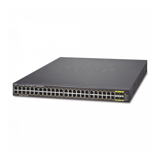
Figure 2-1-1 shows the front panel of the Managed Switch. WGSW-48040HP Front Panel Figure 2-1-1: Front Panels of WGSW-48040HP ■ Gigabit TP interface 10/100/1000Base-T Copper, RJ-45 Twist-Pair: Up to 100 meters. ■ SFP slots 100/1000Base-X mini-GBIC slot, SFP (Small Factor Pluggable) transceiver module: From 550 meters to 2km (multi-mode fiber), up to above 10/20/30/40/50/70/120 kilometers (single-mode fiber). -
Page 22: Led Indications
The front panel LEDs indicate instant status of power and system status, fan status, port links / PoE in-use and data activity; they help monitor and troubleshoot when needed. Figure 2-1-2 shows the LED indications of the Managed Switch. WGSW-48040HP LED Indication Figure 2-1-2: WGSW-48040HP LED at Front Panel WGSW-48040HP LED Indication Table ■ System Color Function Green Lights to indicate that the Switch has power. -
Page 23: Switch Rear Panel
Managed Switch. WGSW-48040HP Rear Panel Figure 2-1-3: Rear Panel of WGSW-48040HP ■ Console Port The console port is a RJ-45 type, RS-232 serial port connector. It is an interface for connecting a terminal directly. Through the console port, it provides rich diagnostic information including IP Address setting, factory reset, port management, link status and system setting. -
Page 24: Installing The Switch
User’s Manual of WGSW-48040HP 2.2 Installing the Switch This section describes how to install your Managed Switch and make connections to the Managed Switch. Please read the following topics and perform the procedures in the order being presented. To install your Managed Switch on a desktop or shelf, simply complete the following steps. -
Page 25: Rack Mounting
User’s Manual of WGSW-48040HP 2.2.2 Rack Mounting To install the Managed Switch in a 19-inch standard rack, please follow the instructions described below. Step 1: Place the Managed Switch on a hard flat surface, with the front panel positioned towards the front side. -
Page 26: Installing The Sfp Transceiver
User’s Manual of WGSW-48040HP Step 6: Proceed with Steps 4 and 5 of session 2.2.1 Desktop Installation to connect the network cabling and supply power to the Managed Switch. 2.2.3 Installing the SFP Transceiver The sections describe how to insert an SFP transceiver into an SFP slot. The SFP transceivers are hot-pluggable and hot-swappable. - Page 27 User’s Manual of WGSW-48040HP Fast Ethernet Transceiver (100Base-BX, Single Fiber Bi-Directional SFP) Connector Model Speed (Mbps) Fiber Mode Distance Wavelength (TX) Wavelength (RX) Operating Temp. Interface 0 ~ 60 ℃ MFB-FA20 WDM(LC) Single Mode 20km 1310nm 1550nm MFB-FB20 WDM(LC) Single Mode...
- Page 28 Fast Ethernet SFP transceiver are similar. Before we connect the WGSW-48040HP to the other network device, we have to make sure both sides of the SFP transceivers are with the same media type, for example: 1000Base-SX to 1000Base-SX, 1000Bas-LX to 1000Base-LX.
- Page 29 User’s Manual of WGSW-48040HP Figure 2-2-5: How to Pull Out the SFP Transceiver Never pull out the module without lifting up the lever of the module and turning it to a horizontal position. Directly pulling out the module could damage the module and the SFP...
-
Page 30: Switch Management
User’s Manual of WGSW-48040HP 3. SWITCH MANAGEMENT This chapter explains the methods that you can use to configure management access to the Managed Switch. It describes the types of management applications and the communication and management protocols that deliver data between your management device (workstation or personal computer) and the system. -
Page 31: Management Access Overview
User’s Manual of WGSW-48040HP 3.2 Management Access Overview The Managed Switch gives you the flexibility to access and manage it using any or all of the following methods: An administration console Web browser interface An external SNMP-based network management application ... -
Page 32: Administration Console
User’s Manual of WGSW-48040HP 3.3 Administration Console The administration console is an internal, character-oriented, and command line user interface for performing system administration such as displaying statistics or changing option settings. Using this method, you can view the administration console from a terminal, personal computer, Apple Macintosh, or workstation connected to the Managed Switch's console (serial) port. -
Page 33: Web Management
User’s Manual of WGSW-48040HP You can change these settings, if desired, after you log on. This management method is often preferred because you can remain connected and monitor the system during system reboots. Also, certain error messages are sent to the serial port, regardless of the interface through which the associated action was initiated. -
Page 34: Snmp-Based Network Management
User’s Manual of WGSW-48040HP 3.5 SNMP-based Network Management You can use an external SNMP-based application to configure and manage the Managed Switch, such as SNMP Network Manager, HP Openview Network Node Management (NNM) or What’s Up Gold. This management method requires the SNMP agent on the switch and the SNMP Network Management Station to use the same community string . - Page 35 User’s Manual of WGSW-48040HP If there are two LAN cards or above in the same administrator PC, choose a different LAN card by using the “Select Adapter” tool. Press “Refresh” button for the currently connected devices in the discovery list as the screen shows below:...
-
Page 36: Web Configuration
User’s Manual of WGSW-48040HP 4. WEB CONFIGURATION This section introduces the configuration and functions of the Web-based management from Managed Switch. About Web-based Management The Managed Switch offers management features that allow users to manage the Managed Switch from anywhere on the network through a standard browser such as Microsoft Internet Explorer. - Page 37 User’s Manual of WGSW-48040HP username/password you have changed via console) to login the main screen of Managed Switch. The login screen in Figure 4-1-2 appears. Figure 4-1-2: Login Screen Default User name: admin Default Password: admin After entering the username and password, the main screen appears as shown in Figure 4-1-3.
-
Page 38: Main Web Page
User’s Manual of WGSW-48040HP Now, you can use the Web management interface to continue the switch management or manage the Managed Switch by Web interface. The Switch Menu on the left of the web Page lets you access all the commands and statistics the Managed Switch provides. - Page 39 User’s Manual of WGSW-48040HP Main Menu Using the onboard web agent, you can define system parameters, manage and control the Managed Switch, and all its ports, or monitor network conditions. Via the Web-Management, the administrator can set up the Managed Switch by selecting the functions those listed in the Main Function.
-
Page 40: System
User’s Manual of WGSW-48040HP 4.2 System Use the System menu items to display and configure basic administrative details of the Managed Switch. Under the System, the following topics are provided to configure and view the system information. This section has the following items: ■... -
Page 41: System Information
User’s Manual of WGSW-48040HP 4.2.1 System Information The System Infomation Page provides information for the current device information. System Information Page helps a switch administrator to identify the hardware MAC address, software version and system uptime. The screen in Figure 4-2-1 appears. -
Page 42: Ip Configuration
User’s Manual of WGSW-48040HP 4.2.2 IP Configuration The IP Configuration includes the IP Configuration, IP Interface and IP Routes. The configured column is used to view or change the IP configuration. The maximum number of interfaces supported is 128 and the maximum number of routes is 32. - Page 43 User’s Manual of WGSW-48040HP should be preferred. DNS Proxy When DNS proxy is enabled, system will relay DNS requests to the currently configured DNS server, and reply as a DNS resolver to the client devices on the network. IP Address Delete Select this option to delete an existing IP interface.
-
Page 44: Ip Status
User’s Manual of WGSW-48040HP 4.2.3 IP Status IP Status displays the status of the IP protocol layer. The status is defined by the IP interfaces, the IP routes and the neighbour cache (ARP cache) status. The screen in Figure 4-2-3 appears. -
Page 45: Users Configuration
User’s Manual of WGSW-48040HP 4.2.4 Users Configuration This Page provides an overview of the current users. Currently the only way to login as another user on the web server is to close and reopen the browser. After setup is completed, press “Apply” button to take effect. Please login web interface with... - Page 46 User’s Manual of WGSW-48040HP Figure 4-2-5: Add / Edit User Configuration Page Screenshot The Page includes the following fields: Object Description Username A string identifying the user name that this entry should belong to. The allowed string length is 1 to 31. The valid user name is a combination of letters, numbers and underscores.
- Page 47 User’s Manual of WGSW-48040HP Once the new user is added, the new user entry shown in the Users Configuration Page. Figure 4-2-6: User Configuration Page Screenshot If you forget the new password after changing the default password, please press the “Reset”...
-
Page 48: Privilege Levels
User’s Manual of WGSW-48040HP 4.2.5 Privilege Levels This Page provides an overview of the privilege levels. After setup is completed, please press “Apply” button to take effect. Please login web interface with new user name and password and the screen in Figure 4-2-7 appears. - Page 49 User’s Manual of WGSW-48040HP consists of a single module (e.g. LACP, RSTP or QoS), but a few of them contain more than one. The following description defines these privilege level groups in details: System: Contact, Name, Location, Timezone, Log.
-
Page 50: Ntp Configuration
User’s Manual of WGSW-48040HP 4.2.6 NTP Configuration Configure NTP on this Page. NTP is an acronym for Network Time Protocol, a network protocol for synchronizing the clocks of computer systems. NTP uses UDP (data grams) as transport layer. You can specify NTP Servers. The NTP Configuration... -
Page 51: Time
User’s Manual of WGSW-48040HP 4.2.7 Time Configure Time Zone on this Page. A Time Zone is a region that has a uniform standard time for legal, commercial, and social purposes. It is convenient for areas in close commercial or other communication to keep the same time, so time zones tend to follow the boundaries of countries and their subdivisions. -
Page 52: Upnp
User’s Manual of WGSW-48040HP Daylight Saving Time duration to repeat the configuration every year. Select 'Non-Recurring' and configure the Daylight Saving Time duration for single time configuration. ( Default : Disabled ). Start Time Settings Week - Select the starting week number. - Page 53 User’s Manual of WGSW-48040HP Object Description Mode Indicates the UPnP operation mode. Possible modes are: Enabled: Enable UPnP mode operation. Disabled: Disable UPnP mode operation. When the mode is enabled, two ACEs are added automatically to trap UPnP related packets to CPU.
-
Page 54: Dhcp Relay
User’s Manual of WGSW-48040HP 4.2.9 DHCP Relay Configure DHCP Relay on this Page. DHCP Relay is used to forward and to transfer DHCP messages between the clients and the server when they are not on the same subnet domain. The DHCP option 82 enables a DHCP relay agent to insert specific information into a DHCP request packets when forwarding client DHCP packets to a DHCP server and remove the specific information from a DHCP reply packets when forwarding server DHCP packets to a DHCP client. -
Page 55: Dhcp Relay Statistics
User’s Manual of WGSW-48040HP they are not on the same subnet domain. Relay Information Indicates the DHCP relay information mode option operation. Possible modes Mode are: Enabled: Enable DHCP relay information mode operation. When enabling DHCP relay information mode operation, the agent inserts specific... - Page 56 User’s Manual of WGSW-48040HP The Page includes the following fields: Server Statistics Object Description Transmit to Server The packets number that relayed from client to server. Transmit Error The packets number that errors sending packets to clients. Receive from Server The packets number that received packets from server.
-
Page 57: Cpu Load
User’s Manual of WGSW-48040HP 4.2.11 CPU Load This Page displays the CPU load, using a SVG graph. The load is measured as average over the last 100ms, 1sec and 10 seconds intervals. The last 120 samles are graphed, and the last numbers are displayed as text as well. In order to display the SVG graph, your browser must support the SVG format. -
Page 58: System Log
User’s Manual of WGSW-48040HP 4.2.12 System Log The Managed Switch system log information is provided here. The System Log screen in Figure 4-2-15 appears. Figure 4-2-15: System Log Page Screenshot The Page includes the following fields: Object Description ID The ID (>= 1) of the system log entry. -
Page 59: Detailed Log
User’s Manual of WGSW-48040HP : Updates the system log entries, starting from the first available entry ID. : Updates the system log entries, ending at the last entry currently displayed. : Updates the system log entries, starting from the last entry currently displayed. -
Page 60: Remote Syslog
User’s Manual of WGSW-48040HP 4.2.14 Remote Syslog Configure remote syslog on this Page. The Remote Syslog screen in Figure 4-2-17 appears. Figure 4-2-17: Remote Syslog Page Screenshot The Page includes the following fields: Object Description Mode Indicates the server mode operation. When the mode operation is enabled, the syslog message will send out to syslog server. -
Page 61: Smtp Configuration
User’s Manual of WGSW-48040HP 4.2.15 SMTP Configuration This Page facilitates an SMTP Configuration on the switch. The SMTP Configure screen in Figure 4-2-18 appears. Figure 4-2-18: SMTP Configuration Page Screenshot The Page includes the following fields: Object Description SMTP Mode Controls whether SMTP is enabled on this switch. -
Page 62: Web Firmware Upgrade
User’s Manual of WGSW-48040HP 4.2.16 Web Firmware Upgrade This Page facilitates an update of the firmware controlling the switch. The Web Firmware Upgrade screen in Figure 4-2-19 appears. Figure 4-2-19: Web Firmware Upgrade Page Screenshot To open Firmware Upgrade screen, perform the following: Click System ->... -
Page 63: Tftp Firmware Upgrade
User’s Manual of WGSW-48040HP 4.2.17 TFTP Firmware Upgrade The Firmware Upgrade Page provides the functions to allow a user to update the Managed Switch firmware from the TFTP server in the network. Before updating, make sure you have your TFTP server ready and the firmware image is on the TFTP server. -
Page 64: Save Startup Config
User’s Manual of WGSW-48040HP 4.2.18 Save Startup Config This function allows save the current configuration, thereby ensuring that the current active configuration can be used at the next reboot screen in Figure 4-2-22 appears. After saving the configuratioin, the screen Figure 4-2-23 will appear. -
Page 65: Configuration Upload
User’s Manual of WGSW-48040HP 4.2.20 Configuration Upload Configuration Upload page allows the upload the running-config and startup-config on the switch. Please refer to the Figure 4-2-25 shown below. Figure 4-2-25: Configuration Upload Page Screenshot If the destination is running-config, the file will be applied to the switch configuration. This can be done in two ways: ... -
Page 66: Configuration Delete
User’s Manual of WGSW-48040HP 4.2.22 Configuration Delete Configuration Delete page allows to delete the startup-config and default-config files which stored in FLASH. If this is done and the switch is rebooted without a prior Save operation, this effectively resets the switch to default configuration. Please refer to... -
Page 67: Factory Default
User’s Manual of WGSW-48040HP The Page includes the following fields: Object Description Image The flash index name of the firmware image. The name of primary (preferred) image is image, the alternate image is named image.bk. Version The version of the firmware image. -
Page 68: System Reboot
User’s Manual of WGSW-48040HP 4.2.25 System Reboot The Reboot Page enables the device to be rebooted from a remote location. Once the Reboot button is pressed, user have to re-login the WEB interface about 60 seconds later, the System Reboot screen in Figure 4-2-30 appears. -
Page 69: Simple Network Management Protocol
User’s Manual of WGSW-48040HP 4.3 Simple Network Management Protocol 4.3.1 SNMP Overview The Simple Network Management Protocol (SNMP) is an application layer protocol that facilitates the exchange of management information between network devices. It is part of the Transmission Control Protocol/Internet Protocol (TCP/IP) protocol suite. -
Page 70: Snmp System Configuration
User’s Manual of WGSW-48040HP SNMP community An SNMP community is the group that devices and management stations running SNMP belong to. It helps define where information is sent. The community name is used to identify the group. A SNMP device or agent may belong to more than one SNMP community. - Page 71 User’s Manual of WGSW-48040HP SNMP v2c: Set SNMP supported version 2c. SNMP v3: Set SNMP supported version 3. Read Community Indicates the community read access string to permit access to SNMP agent. The allowed string length is 0 to 255, and the allowed content is the ASCII characters from 33 to 126.
-
Page 72: Snmp Trap Configuration
User’s Manual of WGSW-48040HP 4.3.3 SNMP Trap Configuration Configure SNMP trap on this Page. The SNMP Trap Configuration screen in Figure 4-3-2 appears. Figure 4-3-2: SNMP Trap Configuration Page Screenshot The Page includes the following fields: Object Description Trap Config Indicates which trap Configuration's name for configuring. - Page 73 User’s Manual of WGSW-48040HP Trap Destination Indicates the SNMP trap destination address. It allow a valid IP address in dotted Address decimal notation ('x.y.z.w'). And it also allow a valid hostname. A valid hostname is a string drawn from the alphabet (A-Za-z), digits (0-9), dot (.), dash (-). Spaces are not allowed, the first character must be an alpha character, and the first and last characters must not be a dot or a dash.
-
Page 74: Snmp System Information
User’s Manual of WGSW-48040HP LLDP: Enable/disable LLDP trap. AAA Indicates that the AAA group's traps. Possible traps are: Authentication Fail : Enable/disable SNMP trap authentication failure trap. Switch Indicates that the Switch group's traps. Possible traps are: ... -
Page 75: Snmpv3 Configuration
User’s Manual of WGSW-48040HP Buttons : Click to apply changes : Click to undo any changes made locally and revert to previously saved values. 4.3.5 SNMPv3 Configuration 4.3.5.1 SNMPv3 Communities Configure SNMPv3 communities table on this Page. The entry index key is Community. The SNMPv3 Communities screen in Figure 4-3-4 appears. -
Page 76: Snmpv3 Users
User’s Manual of WGSW-48040HP 4.3.5.2 SNMPv3 Users Configure SNMPv3 users table on this Page. The entry index keys are Engine ID and User Name. The SNMPv3 Users screen Figure 4-3-5 appears. Figure 4-3-5: SNMPv3 Users Configuration Page Screenshot The Page includes the following fields:... -
Page 77: Snmpv3 Groups
User’s Manual of WGSW-48040HP MD5: An optional flag to indicate that this user using MD5 authentication protocol. SHA: An optional flag to indicate that this user using SHA authentication protocol. The value of security level cannot be modified if entry already exist. That means must first ensure that the value is set correctly. -
Page 78: Snmpv3 Views
User’s Manual of WGSW-48040HP The Page includes the following fields: Object Description Delete Check to delete the entry. It will be deleted during the next save. Security Model Indicates the security model that this entry should belong to. Possible security models are: ... -
Page 79: Snmpv3 Access
User’s Manual of WGSW-48040HP View Name A string identifying the view name that this entry should belong to. The allowed string length is 1 to 32, and the allowed content is the ASCII characters from 33 to 126. ... - Page 80 User’s Manual of WGSW-48040HP to 126. Security Model Indicates the security model that this entry should belong to. Possible security models are: any: Accepted any security model (v1|v2c|usm). v1: Reserved for SNMPv1. v2c: Reserved for SNMPv2c.
-
Page 81: Port Management
User’s Manual of WGSW-48040HP 4.4 Port Management Use the Port Menu to display or configure the Managed Switch's ports. This section has the following items: Port Configuration Configures port connection settings Port Statistics Overview Lists Ethernet and RMON port statistics Port Statistics Detail ... -
Page 82: Port Statistics Overview
User’s Manual of WGSW-48040HP Current Link Speed Provides the current link speed of the port. Configured Link Speed Select any available link speed for the given switch port. Draw the menu bar to select the mode. Auto - Setup Auto negotiation for copper interface. - Page 83 User’s Manual of WGSW-48040HP Figure 4-4-2: Port Statistics Overview Page Screenshot The displayed counters are: Object Description Port The logical port for the settings contained in the same row. Packets The number of received and transmitted packets per port.
-
Page 84: Port Statistics Detail
User’s Manual of WGSW-48040HP : Click to refresh the Page immediately. : Clears the counters for all ports. : Print the Port Statistics Overview result. Auto-refresh : Check this box to enable an automatic refresh of the Page at regular intervals. - Page 85 User’s Manual of WGSW-48040HP Rx and Tx Octets The number of received and transmitted (good and bad) bytes, including FCS, but excluding framing bits. Rx and Tx Unicast The number of received and transmitted (good and bad) unicast packets.
-
Page 86: Sfp Module Information
4.4.4 SFP Module Information The WGSW-48040HP has supported the SFP module with digital diagnostics monitoring (DDM) function, this feature is also known as digital optical monitoring (DOM). You can check the physical or operational status of an SFP module via the SFP Module Information Page. -
Page 87: Port Power Saving Configuration
User’s Manual of WGSW-48040HP Wave Length(nm) Display the wavelength of current SFP module, the wavelength value is get from the SFP module. Use this column to check if the wavelength values of two nodes are the matched while the fiber connection is failed. - Page 88 User’s Manual of WGSW-48040HP mode. For ports that are not EEE-capable the corresponding EEE checkboxes are grayed out and thus impossible to enable EEE for. The EEE port settings relate to the currently selected stack unit, as reflected by the page header.
-
Page 89: Port Power Saving Status
User’s Manual of WGSW-48040HP Controls whether EEE is enabled for this switch port. Buttons : Click to apply changes : Click to undo any changes made locally and revert to previously saved values. 4.4.6 Port Power Saving Status This page provides the current Port Power Saving Status. -
Page 90: Port Mirror
User’s Manual of WGSW-48040HP ActiPHY Shows if the system is currently saving power due to ActiPHY. PerfectReach Savings Shows if the system is currently saving power due to PerfectReach. Buttons Auto-refresh : Check this box to enable an automatic refresh of the Page at regular intervals. - Page 91 User’s Manual of WGSW-48040HP Figure 4-4-8: Mirror Configuration Page Screenshot The Page includes the following fields: Object Description Port to mirror on Frames from ports that have either source (rx) or destination (tx) mirroring enabled are mirrored to this port. Disabled disables mirroring.
-
Page 92: Link Aggregation
User’s Manual of WGSW-48040HP 4.5 Link Aggregation Port Aggregation optimizes port usage by linking a group of ports together to form a single Link Aggregated Groups (LAGs). Port Aggregation multiplies the bandwidth between the devices, increases port flexibility, and provides link redundancy. - Page 93 User’s Manual of WGSW-48040HP The Link Aggregation Control Protocol (LACP) provides a standardized means for exchanging information between Partner Systems that require high speed redundant links. Link aggregation lets you group up to eight consecutive ports into a single dedicated connection. This feature can expand bandwidth to a device on the network. LACP operation requires full-duplex mode, more detail information refer to the IEEE 802.3ad standard.
-
Page 94: Static Aggregation
User’s Manual of WGSW-48040HP 4.5.1 Static Aggregation This Page is used to configure the Aggregation hash mode and the aggregation group. The aggregation hash mode settings are global, whereas the aggregation group relate to the currently selected stack unit, as reflected by the Page header. - Page 95 User’s Manual of WGSW-48040HP Figure 4-5-3: Aggregation Group Configuration Page Screenshot The Page includes the following fields: Description .Object Group ID Indicates the group ID for the settings contained in the same row. Group ID "Normal" indicates there is no aggregation. Only one group ID is valid per port.
-
Page 96: Lacp Configuration
User’s Manual of WGSW-48040HP 4.5.2 LACP Configuration Link Aggregation Control Protocol (LACP) - LACP LAG negotiate Aggregated Port links with other LACP ports located on a different device. LACP allows switches connected to each other to discover automatically whether any ports are member of the same LAG. - Page 97 User’s Manual of WGSW-48040HP The Key value incurred by the port, range 1-65535 . The Auto setting will set the key as appropriate by the physical link speed, 10Mb = 1, 100Mb = 2, 1Gb = 3. Using the Specific setting, a user-defined value can be entered. Ports with the same Key value can participate in the same aggregation group, while ports with different keys cannot.
-
Page 98: Lacp System Status
User’s Manual of WGSW-48040HP 4.5.3 LACP System Status This Page provides a status overview for all LACP instances. The LACP Status Page display the current LACP aggregation Groups and LACP Port status. The LACP System Status screen in Figure 4-5-5 appears. -
Page 99: Lacp Port Status
User’s Manual of WGSW-48040HP 4.5.4 LACP Port Status This Page provides a status overview for LACP status for all ports. The LACP Port Status screen in Figure 4-5-6 appears. Figure 4-5-6: LACP Status Page Screenshot The Page includes the following fields:... -
Page 100: Lacp Port Statistics
User’s Manual of WGSW-48040HP Partner System ID The partner’s System ID (MAC address). Partner Port The partner’s port number connected to this port. Partner Priority The partner's port priority. Buttons : Click to refresh the Page immediately. - Page 101 User’s Manual of WGSW-48040HP The Page includes the following fields: Object Description Port The switch port number. LACP Received Shows how many LACP frames have been sent from each port. LACP Transmitted Shows how many LACP frames have been received at each port.
-
Page 102: Vlan
User’s Manual of WGSW-48040HP 4.6 VLAN 4.6.1 VLAN Overview A Virtual Local Area Network (VLAN) is a network topology configured according to a logical scheme rather than the physical layout. VLAN can be used to combine any collection of LAN segments into an autonomous user group that appears as a single LAN. -
Page 103: Ieee 802.1Q Vlan
User’s Manual of WGSW-48040HP 4.6.2 IEEE 802.1Q VLAN In large networks, routers are used to isolate broadcast traffic for each subnet into separate domains. This Managed Switch provides a similar service at Layer 2 by using VLANs to organize any group of network nodes into separate broadcast domains. -
Page 104: Port Vlan Id
User’s Manual of WGSW-48040HP ■ 802.1Q VLAN Tags The figure below shows the 802.1Q VLAN tag. There are four additional octets inserted after the source MAC address. Their presence is indicated by a value of 0x8100 in the Ether Type field. When a packet's Ether Type field is equal to 0x8100, the packet carries the IEEE 802.1Q/802.1p tag. -
Page 105: Default Vlans
User’s Manual of WGSW-48040HP Every physical port on a switch has a PVID. 802.1Q ports are also assigned a PVID, for use within the switch. If no VLAN are defined on the switch, all ports are then assigned to a default VLAN with a PVID equal to 1. Untagged packets are assigned the PVID of the port on which they were received. -
Page 106: Vlan Port Configuration
User’s Manual of WGSW-48040HP ■ Port Overlapping Port overlapping can be used to allow access to commonly shared network resources among different VLAN groups, such as file servers or printers. Note that if you implement VLANs which do not overlap, but still need to communicate, you can connect them by enabled routing on this switch. - Page 107 User’s Manual of WGSW-48040HP ■ IEEE 802.1Q Tunneling (Q-in-Q) IEEE 802.1Q Tunneling (QinQ) is designed for service providers carrying traffic for multiple customers across their networks. QinQ tunneling is used to maintain customer-specific VLAN and Layer 2 protocol configurations even when different customers use the same internal VLAN IDs.
- Page 108 User’s Manual of WGSW-48040HP Figure 4-6-1 : Global VLAN Configuration Screenshot The Page includes the following fields: Object Description Allowed Access This field shows the allowed Access VLANs, it only affects ports configured as VLANs Access ports. Ports in other modes are members of all VLANs specified in the Allowed VLANs field.
- Page 109 User’s Manual of WGSW-48040HP Port VLAN Configuration The VLAN Port Configuration screen in Figure 4-6-2 appears. Figure 4-6-2 : Port VLAN Configuration Screenshot The Page includes the following fields: Object Description Port This is the logical port number for this row.
- Page 110 User’s Manual of WGSW-48040HP Frames classified to a VLAN that the port is not a member of are discarded By default, all frames but frames classified to the Port VLAN (a.k.a. Native VLAN) get tagged on egress. Frames classified to the Port VLAN do not get C-tagged on egress ...
- Page 111 User’s Manual of WGSW-48040HP be tagged on egress, they will be tagged with an S-tag. S-Custom-Port: ■ On ingress, frames with a VLAN tag with a TPID = 0x8100 or equal to the Ethertype configured for Custom-S ports get classified to the VLAN ID embedded in the tag.
-
Page 112: Vlan Membership Status
User’s Manual of WGSW-48040HP therefore set to 1-4095. The field may be left empty, which means that the port will not become member of any VLANs. Forbidden VLANs A port may be configured to never be member of one or more VLANs. This is particularly useful when dynamic VLAN protocols like MVRP and GVRP must be prevented from dynamically adding ports to VLANs. - Page 113 User’s Manual of WGSW-48040HP communications between a Supplicant, Authenticator, and an Authentication Server. - GVRP : GVRP (GARP VLAN Registration Protocol or Generic VLAN Registration Protocol) is a protocol that facilitates control of virtual local area networks (VLANs) within a larger network .
-
Page 114: Vlan Port Status
User’s Manual of WGSW-48040HP 4.6.5 VLAN Port Status This Page provides VLAN Port Staus. The VLAN Port Status screen in Figure 4-6-5 appears. Figure 4-6-5: VLAN Port Status for Static User Page Screenshot The Page includes the following fields: Object Description ... -
Page 115: Port Isolation
User’s Manual of WGSW-48040HP Frame Type Shows whether the port accepts all frames or only tagged frames. This parameter affects VLAN ingress processing. If the port only accepts tagged frames, untagged frames received on that port are discarded. Port VLAN ID Shows the PVID setting for the port. - Page 116 User’s Manual of WGSW-48040HP or private VLANs to be applied, the switch must first be configured for standard VLAN operation When this is in place, one or more of the configured VLANs can be configured as private VLANs. Ports in a private VLAN fall into one of these two groups: Promiscuous ports ...
- Page 117 User’s Manual of WGSW-48040HP he Page includes the following fields: Object Description Port Members A check box is provided for each port of a private VLAN. When checked, port isolation is enabled on that port. When unchecked, port isolation is disabled on that port.
-
Page 118: Vlan Setting Example
User’s Manual of WGSW-48040HP 4.6.7 VLAN setting example: Separate VLAN 802.1Q VLAN Trunk Port Isolate 4.6.7.1 Two Separate 802.1Q VLANs The diagram shows how the Managed Switch handle Tagged and Untagged traffic flow for two VLANs. VLAN Group 2 and VLAN Group 3 are separated VLAN. - Page 119 User’s Manual of WGSW-48040HP While the packet leaves Port-3, it will keep as a tagged packet with VLAN Tag=2. Tagged packet entering VLAN 2 While [PC-3] transmit a tagged packet with VLAN Tag=2 enters Port-3, [PC-1] and [PC-2] will received the packet through Port-1 and Port-2.
- Page 120 User’s Manual of WGSW-48040HP Figure 4-6-9: Change Port VLAN of Port 1~3 to be VLAN2 and Port VLAN of Port 4~6 to be VLAN3 Checks VLAN Member at VLAN Membership Status: Figure 4-6-10: Check VLAN 2 and 3 Members on VLAN Membership Page...
-
Page 121: Vlan Trunking Between Two 802.1Q Aware Switches
User’s Manual of WGSW-48040HP Figure 4-6-11: Check VLAN 2 and 3 Members on VLAN Membership Page 4.6.7.2 VLAN Trunking between two 802.1Q aware switches The most cases are used for “Uplink ” to other switches. VLANs are separated at different switches, but they need to access with other switches within the same VLAN group. - Page 122 User’s Manual of WGSW-48040HP Add two VLANs – VLAN 2 and VLAN 3 Type 1-3 in Allowed Access VLANs column, the 1-3 is including VLAN1 and 2 and 3. Figure 4-6-13: Add VLAN 2 and VLAN 3 Assign VLAN Member and PVID for each port :...
-
Page 123: Port Isolate
User’s Manual of WGSW-48040HP Figure 4-6-15: VLAN Overlap Port Setting & VLAN 1 – The Public Area Member Assign That is, although the VLAN 2 members: Port-1 to Port-3 and VLAN 3 members: Port-4 to Port-6 also belongs to VLAN 1. But with different PVID settings, packets form VLAN 2 or VLAN 3 is not able to access to the other VLAN. - Page 124 User’s Manual of WGSW-48040HP Setup steps Assign Port Mode Set Port-1~Port-4 in Isolate port. Set Port5 and Port-6 in Promiscuous port. The screen in Figure 4-6-17 appears. Figure 4-6-17: The Configuration of Isolated and Promiscuous Port Assign VLAN Member : VLAN 1 : Port-1,Port-2 ,Port-5 and Port-6 VLAN 2 : Port-3~Port-6.
-
Page 125: Mac-Based Vlan
User’s Manual of WGSW-48040HP Figure 4-6-18: Private VLAN Port Setting Check VLAN Member at VLAN Membership Status: Figure 4-6-19: Check VLAN 1 and 2 Members on VLAN Membership Page 4.6.8 MAC-based VLAN The MAC-based VLAN enties can be configured here. This Page allows for adding and deleting MAC-based VLAN entries and assigning the entries to different ports. -
Page 126: Mac-Based Vlan Status
User’s Manual of WGSW-48040HP Delete To delete a MAC-based VLAN entry, check this box and press save. The entry will be deleted in the stack. MAC Address Indicates the MAC address. VLAN ID Indicates the VLAN ID. -
Page 127: Protocol-Based Vlan
User’s Manual of WGSW-48040HP The Page includes the following fields: Object Description MAC Address Indicates the MAC address. VLAN ID Indicates the VLAN ID. Port Members Port members of the MAC-based VLAN entry. Buttons Auto-refresh : Check this box to refresh the Page automatically. Automatic refresh occurs every 3 seconds. - Page 128 User’s Manual of WGSW-48040HP Value Valid value that can be entered in this text field depends on the option selected from the the preceding Frame Type selection menu. Below is the criteria for three different Frame Types: For Ethernet: Values in the text field when Ethernet is selected as a Frame Type is called etype.
-
Page 129: Protocol-Based Vlan Membership
User’s Manual of WGSW-48040HP 4.6.11 Protocol-based VLAN Membership This Page allows you to map a already configured Group Name to a VLAN for the switch. The Group Name to VLAN Mapping Table screen in Figure 4-6-23 appears. Figure 4-6-23: Group Name to VLAN Mapping Table Page Screenshot... -
Page 130: Spanning Tree Protocol
User’s Manual of WGSW-48040HP 4.7 Spanning Tree Protocol 4.7.1 Theory The Spanning Tree protocol can be used to detect and disable network loops, and to provide backup links between switches, bridges or routers. This allows the switch to interact with other bridging devices in your network to ensure that only one route exists between any two stations on the network, and provide backup links which automatically take over when a primary link goes down. - Page 131 User’s Manual of WGSW-48040HP The path cost to the root from the transmitting port The port identifier of the transmitting port The switch sends BPDUs to communicate and construct the spanning-tree topology. All switches connected to the LAN on which the packet is transmitted will receive the BPDU.
- Page 132 User’s Manual of WGSW-48040HP From forwarding to disabled From disabled to blocking Figure 4-7-1: STP Port State Transitions You can modify each port state by using management software. When you enable STP, every port on every switch in the network goes through the blocking state and then transitions through the states of listening and learning at power up.
- Page 133 User’s Manual of WGSW-48040HP The following are the user-configurable STP parameters for the switch level: Parameter Description Default Value Bridge Identifier(Not user A combination of the User-set priority and 32768 + MAC configurable the switch’s MAC address. except by setting priority...
- Page 134 User’s Manual of WGSW-48040HP User-Changeable STA Parameters The Switch’s factory default setting should cover the majority of installations. However, it is advisable to keep the default settings as set at the factory; unless, it is absolutely necessary. The user changeable parameters in the Switch are as follows: Priority –...
- Page 135 User’s Manual of WGSW-48040HP Figure 4-7-2: Before Applying the STA Rules In this example, only the default STP values are used. Figure 4-7-3: After Applying the STA Rules...
-
Page 136: Stp System Configuration
User’s Manual of WGSW-48040HP The switch with the lowest Bridge ID (switch C) was elected the root bridge, and the ports were selected to give a high port cost between switches B and C. The two (optional) Gigabit ports (default port cost = 20,000) on switch A are connected to one (optional) Gigabit port on both switch B and C. -
Page 137: Basic Settings
User’s Manual of WGSW-48040HP The Page includes the following fields: Basic Settings Object Description The STP protocol version setting. Valid values are STP, RSTP and MSTP. Protocol Version Bridge Priority Controls the bridge priority. Lower numeric values have better priority. The bridge priority plus the MSTI instance number, concatenated with the 6-byte MAC address of the switch forms a Bridge Identifier. -
Page 138: Bridge Status
User’s Manual of WGSW-48040HP reboot. Port Error Recovery The time that has to pass before a port in the error-disabled state can be Timeout enabled. Valid values are between 30 and 86400 seconds (24 hours). The Managed Switch implements the Rapid Spanning Protocol as the default spanning tree protocol. -
Page 139: Cist Port Configuration
User’s Manual of WGSW-48040HP Auto-refresh : Check this box to refresh the Page automatically. Automatic refresh occurs every 3 seconds. : Click to refresh the Page immediately. 4.7.4 CIST Port Configuration This Page allows the user to inspect the current STP CIST port configurations, and possibly change them as well. The CIST... - Page 140 User’s Manual of WGSW-48040HP path cost ports are chosen as forwarding ports in favor of higher path cost ports. Valid values are in the range 1 to 200000000. Priority Controls the port priority. This can be used to control priority of ports having identical port cost.
- Page 141 User’s Manual of WGSW-48040HP By default, the system automatically detects the speed and duplex mode used on each port, and configures the path cost according to the values shown below. Path cost “0” is used to indicate auto-configuration mode. When the short path cost method is selected and the default path cost recommended by the IEEE 8021w standard exceeds 65,535, the default is set to 65,535.
-
Page 142: Msti Priorities
User’s Manual of WGSW-48040HP 4.7.5 MSTI Priorities This Page allows the user to inspect the current STP MSTI bridge instance priority configurations, and possibly change them as well. The MSTI Priority screen in Figure 4-7-7 appears. Figure 4-7-7: MSTI Priority Page Screenshot... -
Page 143: Msti Configuration
User’s Manual of WGSW-48040HP 4.7.6 MSTI Configuration This Page allows the user to inspect the current STP MSTI bridge instance priority configurations, and possibly change them as well. The MSTI Configuration screen in Figure 4-7-8 appears. Figure 4-7-8: MSTI Configuration Page Screenshot... -
Page 144: Msti Port Configuration
User’s Manual of WGSW-48040HP Object Description MSTI The bridge instance. The CIST is not available for explicit mapping, as it will receive the VLANs not explicitly mapped. VLANs Mapped The list of VLAN's mapped to the MSTI. The VLANs must be separated with comma and/or space. - Page 145 User’s Manual of WGSW-48040HP Figure 4-7-10 : MST1 MSTI Port Configuration Page Screenshot The Page includes the following fields: MSTx MSTI Port Configuration Object Description Port The switch port number of the corresponding STP CIST (and MSTI) port. Path Cost Controls the path cost incurred by the port.
-
Page 146: Port Status
User’s Manual of WGSW-48040HP : Click to set MSTx configuration : Click to apply changes : Click to undo any changes made locally and revert to previously saved values. 4.7.8 Port Status This Page displays the STP CIST port status for port physical ports in the currently selected switch. -
Page 147: Port Statistics
User’s Manual of WGSW-48040HP following values: Disabled ■ Learning ■ Forwarding ■ Uptime The time since the bridge port was last initialized. Buttons : Click to refresh the Page immediately. Auto-refresh : Check this box to refresh the Page automatically. Automatic refresh occurs every 3 seconds 4.7.9 Port Statistics... -
Page 148: Multicast
User’s Manual of WGSW-48040HP 4.8 Multicast 4.8.1 IGMP Snooping The Internet Group Management Protocol (IGMP) lets host and routers share information about multicast groups memberships. IGMP snooping is a switch feature that monitors the exchange of IGMP messages and copies them to the CPU for feature processing. - Page 149 User’s Manual of WGSW-48040HP Figure 4-8-2: Multicast Flooding Figure 4-8-3: IGMP Snooping Multicast Stream Control...
- Page 150 User’s Manual of WGSW-48040HP IGMP Versions 1 and 2 Multicast groups allow members to join or leave at any time. IGMP provides the method for members and multicast routers to communicate when joining or leaving a multicast group. IGMP version 1 is defined in RFC 1112. It has a fixed packet size and no optional data.
- Page 151 User’s Manual of WGSW-48040HP message, and query messages that are specific to a given group. The states a computer will go through to join or to leave a multicast group are shown below: Figure 4-8-4: IGMP State Transitions IGMP Querier –...
-
Page 152: Profile Table
User’s Manual of WGSW-48040HP 4.8.2 Profile Table This page provides IPMC Profile related configurations. The IPMC profile is used to deploy the access control on IP multicast streams. It is allowed to create at maximum 64 Profiles with at maximum 128 corresponding rules for each. The Profile Table... -
Page 153: Address Entry
User’s Manual of WGSW-48040HP Buttons : Click to add new IPMC profile. Specify the name and configure the new entry. Click "Save”. : Click to apply changes Click to undo any changes made locally and revert to previously saved values. -
Page 154: Igmp Snooping Configuration
User’s Manual of WGSW-48040HP : Click to apply changes Click to undo any changes made locally and revert to previously saved values. Refreshes the displayed table starting from the input fields. Updates the table starting from the first entry in the IPMC Profile Address Configuration. - Page 155 User’s Manual of WGSW-48040HP The Page includes the following fields: Object Description Snooping Enabled Enable the Global IGMP Snooping. Unregistered IPMCv4 Enable unregistered IPMCv4 traffic flooding. Flooding Enabled The flooding control takes effect only when IGMP Snooping is enabled.
-
Page 156: Igmp Snooping Vlan Configuration
User’s Manual of WGSW-48040HP 4.8.5 IGMP Snooping VLAN Configuration Each Page shows up to 99 entries from the VLAN table, default being 20, selected through the "entries per Page" input field. When first visited, the web Page will show the first 20 entries from the beginning of the VLAN Table. The first displayed will be the one with the lowest VLAN ID found in the VLAN Table. - Page 157 User’s Manual of WGSW-48040HP PRI (PRI) Priority of Interface. It indicates the IGMP control frame priority level generated by the system. These values can be used to prioritize different classes of traffic. The allowed range is 0 (best effort) to 7 (highest), default interface priority value is 0 ...
-
Page 158: Igmp Snooping Port Group Filtering
User’s Manual of WGSW-48040HP 4.8.6 IGMP Snooping Port Group Filtering In certain switch applications, the administrator may want to control the multicast services that are available to end users. For example, an IP/TV service based on a specific subscription plan. The IGMP filtering feature fulfills this requirement by restricting access to specified multicast services on a switch port, and IGMP throttling limits the number of simultaneous multicast groups a port can join. -
Page 159: Igmp Snooping Status
User’s Manual of WGSW-48040HP Port The logical port for the settings. Filtering Profile Select the IPMC Profile as the filtering condition for the specific port. Summary about the designated profile will be shown by clicking the view button... -
Page 160: Igmp Group Information
User’s Manual of WGSW-48040HP Querier Version Working Querier Version currently. Host Version Working Host Version currently. Querier Status Show the Querier status is "ACTIVE" or "IDLE". Querier Transmitted The number of Transmitted Querier. Querier Received The number of Received Querier. -
Page 161: Igmpv3 Information
User’s Manual of WGSW-48040HP The Page includes the following fields: Object Description VLAN ID VLAN ID of the group. Groups Group address of the group displayed. Port Members Ports under this group. Buttons Auto-refresh : Automatic refresh occurs every 3 seconds. - Page 162 User’s Manual of WGSW-48040HP VLAN ID VLAN ID of the group. Group Group address of the group displayed. Port Switch port number. Mode Indicates the filtering mode maintained per (VLAN ID, port number, Group Address) basis. It can be either Include or Exclude.
-
Page 163: Mld Snooping Configuration
User’s Manual of WGSW-48040HP 4.8.10 MLD Snooping Configuration This Page provides MLD Snooping related configuration. The MLD Snooping Configuration screen in Figure 4-8-13 appears. Figure 4-8-13: MLD Snooping Configuration Page Screenshot The Page includes the following fields: Object Description ... -
Page 164: Mld Snooping Vlan Configuration
User’s Manual of WGSW-48040HP unnecessary leave messages to the router side. Proxy Enable Enable MLD Proxy. This feature can be used to avoid forwarding unnecessary join and leave messages to the router side. Router Port Specify which ports act as router ports. A router port is a port on the Ethernet switch that leads towards the Layer 3 multicast device or MLD querier. - Page 165 User’s Manual of WGSW-48040HP VLAN ID The VLAN ID of the entry. MLD Snooping Enable Enable the per-VLAN MLD Snooping. Up to 32 VLANs can be selected for MLD Snooping. Querier Election Enable to join MLD Querier election in the VLAN. Disable to act as a MLD Non-Querier.
-
Page 166: Mld Snooping Port Group Filtering
User’s Manual of WGSW-48040HP : Click to undo any changes made locally and revert to previously saved values. 4.8.12 MLD Snooping Port Group Filtering In certain switch applications, the administrator may want to control the multicast services that are available to end users. For example, an IP/TV service based on a specific subscription plan. -
Page 167: Mld Snooping Status
User’s Manual of WGSW-48040HP The Page includes the following fields: Object Description Port The logical port for the settings. Filtering Group Select the IPMC Profile as the filtering condition for the specific port. Summary about the designated profile will be shown by clicking the view button. - Page 168 User’s Manual of WGSW-48040HP The Page includes the following fields: Object Description VLAN ID The VLAN ID of the entry. Querier Version Working Querier Version currently. Host Version Working Host Version currently. Querier Status Shows the Querier status is "ACTIVE" or "IDLE".
-
Page 169: Mld Group Information
User’s Manual of WGSW-48040HP 4.8.14 MLD Group Information Entries in the MLD Group Table are shown on this Page. The MLD Group Table is sorted first by VLAN ID, and then by group. Each Page shows up to 99 entries from the MLD Group table, default being 20, selected through the "entries per Page" input field. - Page 170 User’s Manual of WGSW-48040HP The "Start from VLAN", and "group" input fields allow the user to select the starting point in the MLD SFM Information Table. The MLDv2 Information screen in Figure 4-8-18 appears. Figure 4-8-18: MLD SSM Information Page Screenshot...
-
Page 171: Mvr (Multicast Vlan Registration)
User’s Manual of WGSW-48040HP 4.8.16 MVR (Multicaset VLAN Registration) The MVR feature enables multicast traffic forwarding on the Multicast VLANs. In a multicast television application, a PC or a network television or a set-top box can receive the multicast stream. - Page 172 User’s Manual of WGSW-48040HP Figure 4-8-19: MVR Configuration Page Screenshot The Page includes the following fields: Object Description MVR Mode Enable/Disable the Global MVR. The Unregistered Flooding control depends on the current configuration in IGMP/MLD Snooping. It is suggested to enable Unregistered Flooding control when the MVR group table is full.
- Page 173 User’s Manual of WGSW-48040HP MVR Name MVR Name is an optional attribute to indicate the name of the specific MVR VLAN. Maximum length of the MVR VLAN Name string is 16. MVR VLAN Name can only contain alphabets or numbers. When the optional MVR VLAN name is given, it should contain at least one alphabet.
-
Page 174: Mvr Status
User’s Manual of WGSW-48040HP management VLAN ports. Select the port role by clicking the Role symbol to switch the setting. I indicates Inactive; S indicates Source; R indicates Receiver The default Role is Inactive. Immediate Leave Enable the fast leave on the port. -
Page 175: Mvr Groups Information
User’s Manual of WGSW-48040HP : Click to refresh the Page immediately. : Clears all Statistics counters. Auto-refresh : Automatic refresh occurs every 3 seconds. 4.8.18 MVR Groups Information Entries in the MVR Group Table are shown on this Page. The MVR Group Table is sorted first by VLAN ID, and then by group. -
Page 176: Mvr Sfm Information
User’s Manual of WGSW-48040HP 4.8.19 MVR SFM Information Entries in the MVR SFM Information Table are shown on this Page. The MVR SFM (Source-Filtered Multicast) Information Table also contains the SSM (Source-Specific Multicast) information. This table is sorted first by VLAN ID, then by group, and then by Port. - Page 177 User’s Manual of WGSW-48040HP : Updates the table starting from the first entry in the MVR SFM Information Table.
-
Page 178: Quality Of Service
User’s Manual of WGSW-48040HP 4.9 Quality of Service 4.9.1 Understanding QoS Quality of Service (QoS) is an advanced traffic prioritization feature that allows you to establish control over network traffic. QoS enables you to assign various grades of network service to different types of traffic, such as multi-media, video, protocol-specific, time critical, and file-backup traffic. -
Page 179: Port Policing
User’s Manual of WGSW-48040HP 4.9.2 Port Policing This Page allows you to configure the Policer settings for all switch ports. The Port Policing screen in Figure 4-9-1 appears. Figure 4-9-1: QoS Ingress Port Policers Page Screenshot The Page includes the following fields:... -
Page 180: Port Classification
User’s Manual of WGSW-48040HP 4.9.3 Port Classification This Page allows you to configure the basic QoS Ingress Classification settings for all switch ports. The Port Classification screen in Figure 4-9-2 appears. Figure 4-9-2 : QoS Ingress Port Classification Page Screenshot... - Page 181 User’s Manual of WGSW-48040HP The classified CoS can be overruled by a QCL entry. Note: If the default CoS has been dynamically changed, then the actual default CoS is shown in parentheses after the configured default CoS. DPL Controls the default drop precedence level.
-
Page 182: Port Scheduler
User’s Manual of WGSW-48040HP 4.9.4 Port Scheduler This Page provides an overview of QoS Egress Port Schedulers for all switch ports. The Port Scheduler screen in Figure 4-9-3 appears. Figure 4-9-3: QoS Egress Port Schedule Page Screenshot The Page includes the following fields:... -
Page 183: Port Shaping
User’s Manual of WGSW-48040HP 4.9.5 Port Shaping This Page provides an overview of QoS Egress Port Shapers for all switch ports. The Port Shapping screen in Figure 4-9-4 appears. Figure 4-9-4: QoS Egress Port Shapers Page Screenshot The Page includes the following fields:... -
Page 184: Qos Egress Port Schedule And Shapers
User’s Manual of WGSW-48040HP 4.9.5.1 QoS Egress Port Schedule and Shapers The Port Scheduler and Shapers for a specific port are configured on this Page. The QoS Egress Port Schedule and Shaper sscreen in Figure 4-9-5 appears. Figure 4-9-5: QoS Egress Port Schedule and Shapers Page Screenshot... -
Page 185: Port Tag Remarking
User’s Manual of WGSW-48040HP Queue Scheduler Shows the weight in percent for this queue. This parameter is only shown if Percent "Scheduler Mode" is set to "Weighted". Port Shaper Enable Controls whether the port shaper is enabled for this switch port. -
Page 186: Qos Egress Port Tag Remarking
User’s Manual of WGSW-48040HP The Page includes the following fields: Object Description Port The logical port for the settings contained in the same row. Click on the port number in order to configure tag remarking. For more detail, please refer to chapter 4.9.6.1. -
Page 187: Port Dscp
User’s Manual of WGSW-48040HP 4.9.7 Port DSCP This Page allows you to configure the basic QoS Port DSCP Configuration settings for all switch ports. The Port DSCP screen in Figure 4-9-8 appears. Figure 4-9-8: QoS Port DSCP Configuration Page Screenshot... - Page 188 User’s Manual of WGSW-48040HP DSCP=0: Classify if incoming (or translated if enabled) DSCP is 0. Selected: Classify only selected DSCP for which classification is enabled as specified in DSCP Translation window for the specific DSCP. All: Classify all DSCP.
-
Page 189: Dscp-Based Qos
User’s Manual of WGSW-48040HP 4.9.8 DSCP-based QoS This Page allows you to configure the basic QoS DSCP-based QoS Ingress Classification settings for all switches. The DSCP-based QoS screen in Figure 4-9-9 appears. Figure 4-9-9: DSCP-based QoS Ingress Classification Page Screenshot... -
Page 190: Dscp Translation
User’s Manual of WGSW-48040HP 4.9.9 DSCP Translation This Page allows you to configure the basic QoS DSCP Translation settings for all switches. DSCP translation can be done in Ingress or Egress. The DSCP Translation screen in Figure 4-9-10 appears. Figure 4-9-10: DSCP Translation Page Screenshot... - Page 191 User’s Manual of WGSW-48040HP Classify ■ Translate DSCP at Ingress side can be translated to any of (0-63) DSCP values. Classify Click to enable Classification at Ingress side. Egress There is following configurable parameter for Egress side - Remap ■...
-
Page 192: Dscp Classification
User’s Manual of WGSW-48040HP 4.9.10 DSCP Classification This Page allows you to map DSCP value to a QoS Class and DPL value. The DSCP Classification screen in Figure 4-9-11 appears. Figure 4-9-11: DSCP Classification Page Screenshot The Page includes the following fields:... -
Page 193: Qos Control List
User’s Manual of WGSW-48040HP 4.9.11 QoS Control List This Page shows the QoS Control List(QCL), which is made up of the QCEs. Each row describes a QCE that is defined. The maximum number of QCEs is 256 on each switch. -
Page 194: Qos Control Entry Configuration
User’s Manual of WGSW-48040HP Frame Type Indicates the type of frame to look for incomming frames. Possible frame types are: Any: The QCE will match all frame type. ■ Ethernet: Only Ethernet frames (with Ether Type 0x600-0xFFFF) are ■... - Page 195 User’s Manual of WGSW-48040HP The Page includes the following fields: Object Description Port Members Check the checkbox button in case you what to make any port member of the QCL entry. By default all ports will be checked ...
- Page 196 User’s Manual of WGSW-48040HP DSCP Diffserv Code Point value(DSCP): It can be specific value, range of value or 'Any'. DSCP values are in the range 0-63 including BE, CS1-CS7, EF or AF11-AF43 IP Fragment IPv4 frame fragmented option: yes|no|any ■...
-
Page 197: Qcl Status
User’s Manual of WGSW-48040HP 4.9.12 QCL Status This Page shows the QCL status by different QCL users. Each row describes the QCE that is defined. It is a conflict if a specific QCE is not applied to the hardware due to hardware limitations. The maximum number of QCEs is 256 on each switch. The... -
Page 198: Storm Control Configuration
User’s Manual of WGSW-48040HP Conflict Displays Conflict status of QCL entries. As H/W resources are shared by multiple applications. It may happen that resources required to add a QCE may not be available, in that case it shows conflict status as 'Yes', otherwise it is always 'No'. - Page 199 User’s Manual of WGSW-48040HP Figure 4-9-15: Storm Control Configuration Page Screenshot The Page includes the following fields: Object Description Port The port number for which the configuration below applies. Enable Controls whether the storm control is enabled on this switch port.
-
Page 200: Wred
User’s Manual of WGSW-48040HP 4.9.14 WRED This page allows you to configure the Random Early Detection (RED) settings for queue 0 to 5. RED cannot be applied to queue 6 and 7. Through different RED configuration for the queues (QoS classes) it is possible to obtain Weighted Random Early Detection (WRED) operation between queues. - Page 201 User’s Manual of WGSW-48040HP RED Drop Probability Function The following illustration shows the drop probability function with associated parameters. Max. DP 1-3 is the drop probability when the average queue filling level is 100%. Frames marked with Drop Precedence Level 0 are never dropped.
-
Page 202: Qos Statistics
User’s Manual of WGSW-48040HP 4.9.15 QoS Statistics This Page provides statistics for the different queues for all switch ports. The QoS Statistics screen in Figure 4-9-17 appears. Figure 4-9-17: Queuing Counters Page Screenshot The Page includes the following fields: Object Description ... -
Page 203: Voice Vlan Configuration
User’s Manual of WGSW-48040HP 4.9.16 Voice VLAN Configuration The Voice VLAN feature enables voice traffic forwarding on the Voice VLAN, then the switch can classify and schedule network traffic. It is recommended that there be two VLANs on a port - one for voice, one for data. - Page 204 User’s Manual of WGSW-48040HP The Page includes the following fields: Object Description Mode Indicates the Voice VLAN mode operation. We must disable MSTP feature before we enable Voice VLAN. It can avoid the conflict of ingress filter. Possible modes are: Enabled: Enable Voice VLAN mode operation.
-
Page 205: Voice Vlan Oui Table
User’s Manual of WGSW-48040HP 4.9.17 Voice VLAN OUI Table Configure VOICE VLAN OUI table on this Page. The maximum entry number is 16. Modifying the OUI table will restart auto detection of OUI process. The Voice VLAN OUI Table screen in Figure 4-9-19 appears. -
Page 206: Access Control Lists
User’s Manual of WGSW-48040HP 4.10 Access Control Lists ACL is an acronym for Access Control List. It is the list table of ACEs, containing access control entries that specify individual users or groups permitted or denied to specific traffic objects, such as a process or a program. - Page 207 User’s Manual of WGSW-48040HP frames. ARP: The ACE will match ARP/RARP frames. ■ IPv4: The ACE will match all IPv4 frames. ■ IPv4/ICMP: The ACE will match IPv4 frames with ICMP protocol. ■ IPv4/UDP: The ACE will match IPv4 frames with UDP protocol.
-
Page 208: Access Control List Configuration
User’s Manual of WGSW-48040HP 4.10.2 Access Control List Configuration This Page shows the Access Control List (ACL), which is made up of the ACEs defined on this switch. Each row describes the ACE that is defined. The maximum number of ACEs is 512 on each switch. - Page 209 User’s Manual of WGSW-48040HP Rate Limiter Indicates the rate limiter number of the ACE. The allowed range is 1 to 16. When Disabled is displayed, the rate limiter operation is disabled. Port Redirect Indicates the port redirect operation of the ACE. Frames matching the ACE are redirected to the port number.
-
Page 210: Ace Configuration
User’s Manual of WGSW-48040HP 4.10.3 ACE Configuration Configure an ACE (Access Control Entry) on this Page. An ACE consists of several parameters. These parameters vary according to the frame type that you select. First select the ingress port for the ACE, and then select the frame type. Different parameter options are displayed depending on the frame type selected. - Page 211 User’s Manual of WGSW-48040HP Ethernet Type: Only Ethernet Type frames can match this ACE. The IEEE ■ 802.3 describes the value of Length/Type Field specifications to be greater than or equal to 1536 decimal (equal to 0600 hexadecimal). ARP: Only ARP frames can match this ACE. Notice the ARP frames won't ■...
- Page 212 User’s Manual of WGSW-48040HP MAC Parameters Object Description SMAC Filter (Only displayed when the frame type is Ethernet Type or ARP.) Specify the source MAC filter for this ACE. Any: No SMAC filter is specified. (SMAC filter status is "don't-care".) ■...
- Page 213 User’s Manual of WGSW-48040HP ARP Parameters The ARP parameters can be configured when Frame Type "ARP" is selected. Object Description ARP/RARP Specify the available ARP/RARP opcode (OP) flag for this ACE. Any: No ARP/RARP OP flag is specified. (OP is "don't-care".) ■...
- Page 214 User’s Manual of WGSW-48040HP RARP Target MAC Specify whether frames can hit the action according to their target hardware Match address field (THA) settings. 0: RARP frames where THA is not equal to the SMAC address. ■ 1: RARP frames where THA is equal to the SMAC address.
- Page 215 User’s Manual of WGSW-48040HP IP Protocol Value When "Specific" is selected for the IP protocol value, you can enter a specific value. The allowed range is 0 to 255. A frame that hits this ACE matches this IP protocol value.
- Page 216 User’s Manual of WGSW-48040HP that appear. DIP Address When "Host" or "Network" is selected for the destination IP filter, you can enter a specific DIP address in dotted decimal notation. DIP Mask When "Network" is selected for the destination IP filter, you can enter a specific DIP mask in dotted decimal notation.
- Page 217 User’s Manual of WGSW-48040HP Hop Limit Specify the hop limit settings for this ACE. zero: IPv6 frames with a hop limit field greater than zero must not be able ■ to match this entry. non-zero: IPv6 frames with a hop limit field greater than zero must be able ■...
- Page 218 User’s Manual of WGSW-48040HP Range: If you want to filter a specific TCP/UDP source range filter with this ■ ACE, you can enter a specific TCP/UDP source range value. A field for entering a TCP/UDP source value appears. TCP/UDP Source No.
- Page 219 User’s Manual of WGSW-48040HP TCP PSH Specify the TCP "Push Function" (PSH) value for this ACE. 0: TCP frames where the PSH field is set must not be able to match this ■ entry. 1: TCP frames where the PSH field is set must be able to match this entry.
-
Page 220: Acl Ports Configuration
User’s Manual of WGSW-48040HP 4.10.4 ACL Ports Configuration Configure the ACL parameters (ACE) of each switch port. These parameters will affect frames received on a port unless the frame matches a specific ACE. The ACL Ports Configuration screen in Figure 4-10-4 appears. - Page 221 User’s Manual of WGSW-48040HP value is "Disabled". Logging Specify the logging operation of this port. The allowed values are: Enabled: Frames received on the port are stored in the System Log. ■ Disabled: Frames received on the port are not logged.
-
Page 222: Acl Rate Limiter Configuration
User’s Manual of WGSW-48040HP 4.10.5 ACL Rate Limiter Configuration Configure the rate limiter for the ACL of the switch. The ACL Rate Limiter Configuration screen in Figure 4-10-5 appears. Figure 4-10-5: ACL Rate Limiter Configuration Page Screenshot The Page includes the following fields:... -
Page 223: Authentication
User’s Manual of WGSW-48040HP 4.11 Authentication This section is to control the access of the Managed Switch, includes the user access and management control. The Authentication section contains links to the following main topics: IEEE 802.1X Port-Based Network Access Control ... -
Page 224: Understanding Ieee 802.1X Port-Based Authentication
User’s Manual of WGSW-48040HP to authenticate. The disadvantage is that MAC addresses can be spoofed by malicious users, equipment whose MAC address is a valid RADIUS user can be used by anyone, and only the MD5-Challenge method is supported. The 802.1X and MAC-Based Authentication configuration consists of two sections, a system- and a port-wide. - Page 225 User’s Manual of WGSW-48040HP Figure 4-11-1 Client—the device (workstation) that requests access to the LAN and switch services and responds to requests from the switch. The workstation must be running 802.1X-compliant client software such as that offered in the Microsoft Windows XP operating system.
- Page 226 User’s Manual of WGSW-48040HP authentication server, the server's frame header is removed, leaving the EAP frame, which is then encapsulated for Ethernet and sent to the client. Authentication Initiation and Message Exchange The switch or the client can initiate authentication. If you enable authentication on a port by using the dot1x port-control auto interface configuration command, the switch must initiate authentication when it determines that the port link state transitions from down to up.
-
Page 227: Authentication Configuration
User’s Manual of WGSW-48040HP Ports in Authorized and Unauthorized States The switch port state determines whether or not the client is granted access to the network. The port starts in the unauthorized state. While in this state, the port disallows all ingress and egress traffic except for 802.1X protocol packets. When a client is successfully authenticated, the port transitions to the authorized state, allowing all traffic for the client to flow normally. -
Page 228: Network Access Server Configuration
User’s Manual of WGSW-48040HP The Page includes the following fields: Object Description Client The management client for which the configuration below applies. Authentication Method Authentication Method can be set to one of the following values: None: authentication is disabled and login is not possible. - Page 229 User’s Manual of WGSW-48040HP Figure 4-11-4: Network Access Server Configuration Page Screenshot The Page includes the following fields: System Configuration Object Description Mode Indicates if NAS is globally enabled or disabled on the switch. If globally disabled, all ports are allowed forwarding of frames.
- Page 230 User’s Manual of WGSW-48040HP configuration has changed. It does not involve communication between the switch and the client, and therefore doesn't imply that a client is still present on a port. Reauthentication Determines the period, in seconds, after which a connected client must be Period reauthenticated.
- Page 231 User’s Manual of WGSW-48040HP In MAC-based Auth. mode, the The switch will ignore new frames coming from the client during the hold time. The Hold Time can be set to a number between 10 and 1000000 seconds. RADIUS-Assigned QoS...
- Page 232 User’s Manual of WGSW-48040HP enabled. Valid values are in the range [1; 255]. Allow Guest VLAN if The switch remembers if an EAPOL frame has been received on the port for the EAPOL Seen life-time of the port. Once the switch considers whether to enter the Guest VLAN, it will first check if this option is enabled or disabled.
- Page 233 User’s Manual of WGSW-48040HP packets also encapsulate EAP PDUs together with other attributes like the switch's IP address, name, and the supplicant's port number on the switch. EAP is very flexible, in that it allows for different authentication methods, like MD5-Challenge, PEAP, and TLS.
- Page 234 User’s Manual of WGSW-48040HP allowed access. This is the most secure of all the supported modes. In this mode, the Port Security module is used to secure a supplicant's MAC address once successfully authenticated. Multi 802.1X Multi 802.1X is - like Single 802.1X - not an IEEE standard, but a variant that features many of the same characteristics.
- Page 235 User’s Manual of WGSW-48040HP the 802.1X standard. The advantage of MAC-based authentication over port-based 802.1X is that several clients can be connected to the same port (e.g. through a 3rd party switch or a hub) and still require individual authentication, and that the clients don't need special supplicant software to authenticate.
- Page 236 User’s Manual of WGSW-48040HP successfully authenticated. If present and valid, the port's Port VLAN ID will be changed to this VLAN ID, the port will be set to be a member of that VLAN ID, and the port will be forced into VLAN unaware mode. Once assigned, all traffic arriving on the port will be classified and switched on the RADIUS-assigned VLAN ID.
- Page 237 User’s Manual of WGSW-48040HP Single 802.1X Multi 802.1X For trouble-shooting VLAN assignments, use the "Monitor→VLANs→VLAN Membership and VLAN Port" Pages. These Pages show which modules have (temporarily) overridden the current Port VLAN configuration. Guest VLAN Operation: When a Guest VLAN enabled port's link comes up, the switch starts transmitting EAPOL Request Identity frames.
- Page 238 User’s Manual of WGSW-48040HP authentication is globally enabled and the port's Admin State is in an EAPOL-based or MAC-based mode. Clicking these buttons will not cause settings changed on the Page to take effect. Reauthenticate: Schedules a reauthentication to whenever the ■...
-
Page 239: Network Access Overview
User’s Manual of WGSW-48040HP 4.11.4 Network Access Overview This Page provides an overview of the current NAS port states for the selected switch. The Network Access Overview screen in Figure 4-11-5 appears. Figure 4-11-5: Network Access Server Switch Status Page Screenshot... - Page 240 User’s Manual of WGSW-48040HP source MAC address from the most recently received frame from a new client for MAC-based authentication. QoS Class QoS Class assigned to the port by the RADIUS server if enabled. Port VLAN ID The VLAN ID that NAS has put the port in. The field is blank, if the Port VLAN ID is not overridden by NAS.
-
Page 241: Network Access Statistics
User’s Manual of WGSW-48040HP 4.11.5 Network Access Statistics This Page provides detailed NAS statistics for a specific switch port running EAPOL-based IEEE 802.1X authentication. For MAC-based ports, it shows selected backend server (RADIUS Authentication Server) statistics, only. Use the port select box to select which port details to be displayed. - Page 242 User’s Manual of WGSW-48040HP Port Counters Object Description EAPOL Counters These supplicant frame counters are available for the following administrative states: Force Authorized ■ Force Unauthorized ■ Port-based 802.1X ■ Single 802.1X ■ Multi 802.1X ■ Direction Name IEEE Name...
- Page 243 User’s Manual of WGSW-48040HP received by the switch in which the Packet Body Length field is invalid. Total dot1xAuthEapolFrames The number of EAPOL frames of any type that have been transmitted by the switch. Request ID dot1xAuthEapolReqIdFr The number of EAPOL...
- Page 244 User’s Manual of WGSW-48040HP table). Other 802.1X-based: dot1xAuthBackendOther Requests RequestsToSupplicant Counts the number of times that the switch sends an EAP Request packet following the first to the supplicant. Indicates that the backend server chose an EAP-method. MAC-based: Not applicable.
- Page 245 User’s Manual of WGSW-48040HP towards the backend server for a given port (left-most table) or client (right-most table). Possible retransmissions are not counted. Last Supplicant/Client Information about the last supplicant/client that attempted to authenticate. This Info information is available for the following administrative states: Port-based 802.1X...
- Page 246 User’s Manual of WGSW-48040HP Selected Counters Object Description Selected Counters The Selected Counters table is visible when the port is one of the following administrative states: Multi 802.1X ■ MAC-based Auth. ■ The table is identical to and is placed next to the Port Counters table, and will be empty if no MAC address is currently selected.
- Page 247 User’s Manual of WGSW-48040HP • Force Unauthorized • Port-based 802.1X • Single 802.1X Click to clear the counters for the selected port. : This button is available in the following modes: • Multi 802.1X • MAC-based Auth.X Click to clear both the port counters and all of the attached client's counters. The "Last Client" will not be cleared, however.
-
Page 248: Radius
User’s Manual of WGSW-48040HP 4.11.6 RADIUS This Page allows you to configure the RADIUS Servers. The RADIUS Configuration screen in Figure 4-11-7 appears. Figure 4-11-7: RADIUS Server Configuration Page Screenshot The Page includes the following fields: Global Configuration These setting are common for all of the RADIUS Servers. - Page 249 User’s Manual of WGSW-48040HP Key The secret key - up to 63 characters long - shared between the RADIUS server and the switch. NAS-IP-Address The IPv4 address to be used as attribute 4 in RADIUS Access-Request packets. If this field is left blank, the IP address of the outgoing interface is used.
-
Page 250: Tacacs
User’s Manual of WGSW-48040HP 4.11.7 TACACS+ This Page allows you to configure the TACACS+ Servers. The TACACS+ Configuration screen in Figure 4-11-8 appears. Figure 4-11-8: TACACS+ Server Configuration Page Screenshot The Page includes the following fields: Global Configuration These setting are common for all of the TACACS+ Servers. -
Page 251: Radius Overview
User’s Manual of WGSW-48040HP Server Configuration The table has one row for each TACACS+ server and a number of columns, which are: Object Description Delete To delete a TACACS+ server entry, check this box. The entry will be deleted during the next Save. - Page 252 User’s Manual of WGSW-48040HP Figure 4-11-9: RADIUS Authentication/Accounting Server Overview Page Screenshot The Page includes the following fields: RADIUS Authentication Server Status Overview Object Description # The RADIUS server number. Click to navigate to detailed statistics for this server.
- Page 253 User’s Manual of WGSW-48040HP RADIUS Accounting Server Status Overview Object Description # The RADIUS server number. Click to navigate to detailed statistics for this server. IP Address The IP address and UDP port number (in <IP Address>:<UDP Port> notation) of this server.
-
Page 254: Radius Details
User’s Manual of WGSW-48040HP 4.11.9 RADIUS Details This Page provides detailed statistics for a particular RADIUS server. The RADIUS Authentication/Accounting for Server Overview screen in Figure 4-11-10 appears. Figure 4-11-10: RADIUS Authentication/Accounting for Server Overview Page Screenshot The Page includes the following fields: RADIUS Authentication Statistics The statistics map closely to those specified in RFC4668 - RADIUS Authentication Client MIB. - Page 255 User’s Manual of WGSW-48040HP Access radiusAuthClientExtA The number of RADIUS Accepts ccessAccepts Access-Accept packets (valid or invalid) received from the server. Access Rejects radiusAuthClientExtA The number of RADIUS ccessRejects Access-Reject packets (valid or invalid) received from the server. Access radiusAuthClientExtA...
- Page 256 User’s Manual of WGSW-48040HP authentication port and dropped for some other reason. Access radiusAuthClientExtA The number of RADIUS Requests ccessRequests Access-Request packets sent to the server. This does not include retransmissions. Access radiusAuthClientExtA The number of RADIUS Retransmissio ccessRetransmission Access-Request packets retransmitted to the RADIUS authentication server.
- Page 257 User’s Manual of WGSW-48040HP in question. State Shows the state of the server. It takes one of the following values: Disabled: The selected server is disabled. Not Ready: The server is enabled, but IP communication is not yet up and running.
- Page 258 User’s Manual of WGSW-48040HP RADIUS Accounting Statistics The statistics map closely to those specified in RFC4670 - RADIUS Accounting Client MIB. Use the server select box to switch between the backend servers to show details for. Object Description Packet Counters RADIUS accounting server packet counter.
- Page 259 User’s Manual of WGSW-48040HP Retransmissions radiusAccClientExt The number of RADIUS Retransmissions packets retransmitted to the RADIUS accounting server. Pending radiusAccClientExt The number of RADIUS Requests PendingRequests packets destined for the server that have not yet timed out or received a response. This...
- Page 260 User’s Manual of WGSW-48040HP did not reply within the configured timeout. The server has temporarily been disabled, but will get re-enabled when the dead-time expires. The number of seconds left before this occurs is displayed in parentheses. This state is only reachable when more than one server is enabled.
-
Page 261: Windows Platform Radius Server Configuration
User’s Manual of WGSW-48040HP 4.11.10 Windows Platform RADIUS Server Configuration Setup the RADIUS server and assign the client IP address to the Managed switch. In this case, field in the default IP Address of the Managed Switch with 192.168.0.100. And also make sure the shared secret key is as same as the one you had set at the Managed Switch’s 802.1x system configuration –... - Page 262 User’s Manual of WGSW-48040HP Add New RADIUS Cleint on the Windows 2003 server Figure 4-11-12: Windows Server – Add New RADIUS Client Setting Assign the client IP address to the Managed Switch Figure 4-11-13: Windows Server RADIUS Server Setting...
- Page 263 User’s Manual of WGSW-48040HP The shared secret key should be as same as the key configured on the Managed Switch. Figure 4-11-14: Windows Server RADIUS Server Setting Configure ports attribute of 802.1X, the same as “802.1X Port Configuration”. Figure 4-11-15: 802.1x Port Configuration Create user data.
- Page 264 User’s Manual of WGSW-48040HP Figure 4-11-16: Windows 2003 AD Server Setting Path Enter ” Active Directory Users and Computers”, create legal user data; next, right-click a user what you created to enter properties, and what to be noticed:...
- Page 265 User’s Manual of WGSW-48040HP Figure 4-11-17: Add User Properties Screen Figure 4-11-18: Add User Properties Screen Set the Port Authenticate Status to “Force Authorized” if the port is connected to the RADIUS server or the port is an uplink port that is connected to another switch. Or once the 802.1X starts to...
-
Page 266: Client Configuration
User’s Manual of WGSW-48040HP 4.11.11 802.1X Client Configuration Windows XP is originally 802.1X support. As to other operating systems (windows 98SE, ME, 2000), an 802.1X client utility is needed. The following procedures show how to configure 802.1X Authentication in Windows XP. - Page 267 User’s Manual of WGSW-48040HP Figure 4-11-20 Click “OK”. When client has associated with the Managed Switch, a user authentication notice appears in system tray. Click on the notice to continue. Figure 4-11-21: Windows Client Popup Login Request Message...
- Page 268 User’s Manual of WGSW-48040HP Enter the user name, password and the logon domain that your account belongs. 10. Click “OK” to complete the validation process. Figure 4-11-22...
-
Page 269: Security
User’s Manual of WGSW-48040HP 4.12 Security This section is to control the access of the Managed Switch, includes the user access and management control. The Security Page contains links to the following main topics: Port Limit Control Access Management ... - Page 270 User’s Manual of WGSW-48040HP Figure 4-12-1: Port Limit Control Configuration Overview Page Screenshot The Page includes the following fields: System Configuration Object Description Mode Indicates if Limit Control is globally enabled or disabled on the switchstack. If globally disabled, other modules may still use the underlying functionality, but limit checks and corresponding actions are disabled.
- Page 271 User’s Manual of WGSW-48040HP other modules are using the underlying port security for securing MAC addresses, they may have other requirements to the aging period. The underlying port security will use the shorter requested aging period of all modules that use the functionality.
- Page 272 User’s Manual of WGSW-48040HP further action. Trap: If Limit + 1 MAC addresses is seen on the port, send an SNMP trap. If Aging is disabled, only one SNMP trap will be sent, but with Aging enabled, new SNMP traps will be sent everytime the limit gets exceeded.
-
Page 273: Access Management
User’s Manual of WGSW-48040HP 4.12.2 Access Management Configure access management table on this Page. The maximum entry number is 16. If the application's type match any one of the access management entries, it will allow access to the switch. The Access Management Configuration screen in... -
Page 274: Access Management Statistics
User’s Manual of WGSW-48040HP 4.12.3 Access Management Statistics This Page provides statistics for access management. The Access Management Statistics screen in Figure 4-12-3 appears. Figure 4-12-3: Access Management Statistics Overview Page Screenshot The Page includes the following fields: Object Description ... -
Page 275: Https
User’s Manual of WGSW-48040HP 4.12.4 HTTPs Configure HTTPS on this Page. The HTTPS Configuration screen in Figure 4-12-4 appears. Figure 4-12-4: HTTPS Configuration Screen Page Screenshot The Page includes the following fields: Object Description Mode Indicates the HTTPS mode operation. When the current connection is HTTPS, to apply HTTPS disabled mode operation will automatically redirect web browser to an HTTP connection. -
Page 276: Ssh
User’s Manual of WGSW-48040HP 4.12.5 SSH Configure SSH on this Page. This Page shows the Port Security status. Port Security is a module with no direct configuration. Configuration comes indirectly from other modules - the user modules. When a user module has enabled port security on a port, the port is set-up for software-based learning. -
Page 277: Port Security Status
User’s Manual of WGSW-48040HP 4.12.6 Port Security Status This Page shows the Port Security status. Port Security is a module with no direct configuration. Configuration comes indirectly from other modules - the user modules. When a user module has enabled port security on a port, the port is set-up for software-based learning. - Page 278 User’s Manual of WGSW-48040HP The Page includes the following fields: User Module Legend The legend shows all user modules that may request Port Security services. Object Description User Module Name The full name of a module that may request Port Security services.
-
Page 279: Port Security Detail
User’s Manual of WGSW-48040HP 4.12.7 Port Security Detail This Page shows the MAC addresses secured by the Port Security module. Port Security is a module with no direct configuration. Configuration comes indirectly from other modules - the user modules. When a user module has enabled port security on a port, the port is set-up for software-based learning. -
Page 280: Dhcp Snooping
User’s Manual of WGSW-48040HP 4.12.8 DHCP Snooping DHCP Snooping is used to block intruder on the untrusted ports of DUT when it tries to intervene by injecting a bogus DHCP reply packet to a legitimate conversation between the DHCP client and server. - Page 281 User’s Manual of WGSW-48040HP Figure 4-12-8: DHCP Snooping Configuration Screen Page Screenshot The Page includes the following fields: Object Description Snooping Mode Indicates the DHCP snooping mode operation. Possible modes are: Enabled: Enable DHCP snooping mode operation. When enable DHCP snooping mode operation, the request DHCP messages will be forwarded to trusted ports and only allowed reply packets from trusted ports.
-
Page 282: Snooping Table
User’s Manual of WGSW-48040HP 4.12.9 Snooping Table This page display the dynamic IP assigned information after DHCP Snooping mode is disabled. All DHCP clients obtained the dynamic IP address from the DHCP server will be listed in this table except for local VLAN interface IP addresses. -
Page 283: Ip Source Guard Configuration
User’s Manual of WGSW-48040HP 4.12.10 IP Source Guard Configuration IP Source Guard is a secure feature used to restrict IP traffic on DHCP snooping untrusted ports by filtering traffic based on the DHCP Snooping Table or manually configured IP Source Bindings. It helps prevent IP spoofing attacks when a host tries to spoof and use the IP address of another host. - Page 284 User’s Manual of WGSW-48040HP The Page includes the following fields: Object Description Mode of IP Source Enable the Global IP Source Guard or disable the Global IP Source Guard. All Guard Configuration configured ACEs will be lost when the mode is enabled.
-
Page 285: Ip Source Guard Static Table
User’s Manual of WGSW-48040HP 4.12.11 IP Source Guard Static Table This Page provides Static IP Source Guard Table. The Static IP Source Guard Table screen in Figure 4-12-11 appears. Figure 4-12-11: Static IP Source Guard Table Screen Page Screenshot The Page includes the following fields:... -
Page 286: Arp Inspection
User’s Manual of WGSW-48040HP 4.12.12 ARP Inspection ARP Inspection is a secure feature. Several types of attacks can be launched against a host or devices connected to Layer 2 networks by "poisoning" the ARP caches. This feature is used to block such attacks. Only valid ARP requests and responses can go through DUT. - Page 287 User’s Manual of WGSW-48040HP The Page includes the following fields: Object Description Mode of ARP Inspection Enable the Global ARP Inspection or disable the Global ARP Inspection. Configuration Port Mode Configuration Specify ARP Inspection is enabled on which ports. Only when both Global Mode and Port Mode on a given port are enabled, ARP Inspection is enabled on this given port.
-
Page 288: Arp Inspection Static Table
User’s Manual of WGSW-48040HP 4.12.13 ARP Inspection Static Table This Page provides Static ARP Inspection Table. The Static ARP Inspection Table screen in Figure 4-12-13 appears. Figure 4-12-13: Static ARP Inspection Table Screen Page Screenshot The Page includes the following fields:... -
Page 289: Address Table
User’s Manual of WGSW-48040HP 4.13 Address Table Switching of frames is based upon the DMAC address contained in the frame. The Managed Switch builds up a table that maps MAC addresses to switch ports for knowing which ports the frames should go to (based upon the DMAC address in the frame ). -
Page 290: Aging Configuration
User’s Manual of WGSW-48040HP The Page includes the following fields: Aging Configuration By default, dynamic entries are removed from the MAC table after 300 seconds. This removal is also called aging. Object Description Disable Automatic Enables/disables the the automatic aging of dynamic entries Aging ... -
Page 291: Mac Address Table Status
User’s Manual of WGSW-48040HP 4.13.2 MAC Address Table Status Dynamic MAC Table Entries in the MAC Table are shown on this Page. The MAC Table contains up to 8192 entries, and is sorted first by VLAN ID, then by MAC address. The MAC Address Table screen in Figure 4-13-2 appears. -
Page 292: Dynamic Arp Inspection Table
User’s Manual of WGSW-48040HP Auto-refresh : Automatic refresh occurs every 3 seconds. : Refreshes the displayed table starting from the "Start from MAC address" and "VLAN" input fields. : Flushes all dynamic entries. Updates the table starting from the first entry in the MAC Table, i.e. the entry with the lowest VLAN ID and MAC address. -
Page 293: Dynamic Ip Source Guard Table
User’s Manual of WGSW-48040HP MAC Address The MAC address of the entry. IP Address The IP address of the entry. Buttons Auto-refresh : Check this box to refresh the Page automatically. Automatic refresh occurs every 3 seconds. : Refreshes the displayed table starting from the "Start from MAC address" and "VLAN" input fields. - Page 294 User’s Manual of WGSW-48040HP Object Description Port The port number for which the status applies. Click the port number to see the status for this particular port. VLAN ID The VLAN ID of the entry. IP Address The IP address of the entry.
-
Page 295: Lldp
User’s Manual of WGSW-48040HP 4.14 LLDP 4.14.1 Link Layer Discovery Protocol Link Layer Discovery Protocol (LLDP) is used to discover basic information about neighboring devices on the local broadcast domain. LLDP is a Layer 2 protocol that uses periodic broadcasts to advertise information about the sending device. Advertised information is represented in Type Length Value (TLV) format according to the IEEE 802.1ab standard, and can include details... -
Page 296: Lldp Port Configuration
User’s Manual of WGSW-48040HP The Page includes the following fields: LLDP Parameters Object Description Tx Interval The switch is periodically transmitting LLDP frames to its neighbors for having the network discovery information up-to-date. The interval between each LLDP frame is determined by the Tx Interval value. Valid values are restricted to 5 - 32768 seconds. - Page 297 User’s Manual of WGSW-48040HP from neighbor units is analyzed. Tx only The switch will drop LLDP information received from neighbors, but will send out LLDP information. Disabled The switch will not send out LLDP information, and will drop LLDP information received from neighbors.
-
Page 298: Lldp Med Configuration
User’s Manual of WGSW-48040HP Buttons : Click to apply changes Click to undo any changes made locally and revert to previously saved values. 4.14.3 LLDP MED Configuration This Page allows you to configure the LLDP-MED. The LLDPMED Configuration screen in Figure 4-14-2 appears. - Page 299 User’s Manual of WGSW-48040HP between the protocol and the application layers on top of the protocol, in order to achieve these related properties. Initially, a Network Connectivity Device will only transmit LLDP TLVs in an LLDPDU. Only after an LLDP-MED Endpoint Device is detected, will an LLDP-MED capable Network Connectivity Device start to advertise LLDP-MED TLVs in outgoing LLDPDUs on the associated port.
- Page 300 User’s Manual of WGSW-48040HP building, 0.0 represents the floor level associated with ground level at the main entrance. The Map Datum used for the coordinates given in this Option Map Datum WGS84: (Geographical 3D) - World Geodesic System 1984, CRS Code 4327, Prime Meridian Name: Greenwich.
- Page 301 User’s Manual of WGSW-48040HP Name Name (residence and office occupant) - Example: Flemming Jahn Zip code Postal/zip code - Example: 2791 Building Building (structure) - Example: Low Library Apartment Unit (Apartment, suite) - Example: Apt 42 ...
- Page 302 User’s Manual of WGSW-48040HP 1. Voice 2. Guest Voice 3. Softphone Voice 4. Video Conferencing 5. Streaming Video 6. Control / Signaling (conditionally support a separate network policy for the media types above) A large network may support multiple VoIP policies across the entire organization, and different policies per application type.
- Page 303 User’s Manual of WGSW-48040HP frequently does not support multiple VLANs, if at all, and are typically configured to use an 'untagged’ VLAN or a single 'tagged’ data specific VLAN. When a network policy is defined for use with an 'untagged’...
-
Page 304: Lldp-Med Neighbor
User’s Manual of WGSW-48040HP Adding a new policy to add a new policy. Specify the Application type, Click Tag, VLAN ID, L2 Priority and DSCP for the new policy. Click "Save". The number of policies supported is 32 Port Policies Configuration Every port may advertise a unique set of network policies or different attributes for the same network policies, based on the authenticated user identity or port configuration. - Page 305 User’s Manual of WGSW-48040HP Device Type LLDP-MED Devices are comprised of two primary Device Types: Network Connectivity Devices and Endpoint Devices. LLDP-MED Network Connectivity Device Definition LLDP-MED Network Connectivity Devices, as defined in TIA-1057, provide access to the IEEE 802 based LAN infrastructure for LLDP-MED Endpoint Devices.
- Page 306 User’s Manual of WGSW-48040HP Discovery services defined in this class include media-type-specific network layer policy discovery. LLDP-MED Communication Endpoint (Class III) The LLDP-MED Communication Endpoint (Class III) definition is applicable to all endpoint products that act as end user communication appliances supporting IP media.
- Page 307 User’s Manual of WGSW-48040HP and other similar appliances supporting real-time interactive video/audio services. Streaming Video - for use by broadcast or multicast based video content distribution and other similar applications supporting streaming video services that require specific network policy treatment. Video applications relying on TCP with buffering would not be an intended use of this application type.
-
Page 308: Neighbor
User’s Manual of WGSW-48040HP : Click to refresh the Page immediately. Auto-refresh Check this box to refresh the Page automatically. Automatic refresh occurs every 3 seconds. 4.14.5 Neighbor This Page provides a status overview for all LLDP neighbors. The displayed table contains a row for each port on which an LLDP neighbor is detected. -
Page 309: Port Statistics
User’s Manual of WGSW-48040HP entities to assist the discovery by the network management. This could for instance hold the neighbor's IP address. Buttons : Click to refresh the Page immediately. Auto-refresh Check this box to refresh the Page automatically. Automatic refresh occurs every 3 seconds. - Page 310 User’s Manual of WGSW-48040HP Total Neighbors Shows the number of new entries added since switch reboot. Entries Added Total Neighbors Shows the number of new entries deleted since switch reboot. Entries Deleted Total Neighbors Shows the number of LLDP frames dropped due to that the entry table was full.
- Page 311 User’s Manual of WGSW-48040HP Auto-refresh Check this box to refresh the Page automatically. Automatic refresh occurs every 3 seconds.
-
Page 312: Network Diagnostics
User’s Manual of WGSW-48040HP 4.15 Network Diagnostics This section provide the Physical layer and IP layer network diagnostics tools for troubleshoot. The diagnostic tools are designed for network manager to help them quickly diagnose problems between point to point and better service customers. -
Page 313: Ping
User’s Manual of WGSW-48040HP 4.15.1 Ping This Page allows you to issue ICMP PING packets to troubleshoot IP connectivity issues. After you press “Start”, 5 ICMP packets are transmitted, and the sequence number and roundtrip time are displayed upon reception of a reply. The Page refreshes automatically until responses to all packets are received, or until a timeout occurs. The... -
Page 314: Ipv6 Ping
User’s Manual of WGSW-48040HP 4.15.2 IPv6 Ping This Page allows you to issue ICMPv6 PING packets to troubleshoot IPv6 connectivity issues. After you press “Start”, 5 ICMPv6 packets are transmitted, and the sequence number and roundtrip time are displayed upon reception of a reply. -
Page 315: Remote Ip Ping Test
User’s Manual of WGSW-48040HP 4.15.3 Remote IP Ping Test This Page allows you to issue ICMP PING packets to troubleshoot IP connectivity issues on special port. After you press “Test”, 5 ICMP packets are transmitted, and the sequence number and roundtrip time are displayed upon reception of a reply. -
Page 316: Cable Diagnostics
User’s Manual of WGSW-48040HP Buttons : Click to apply changes Click to undo any changes made locally and revert to previously saved values. : Clears the IP Address and the result of ping value. 4.15.4 Cable Diagnostics This Page is used for running the Cable Diagnostics. - Page 317 User’s Manual of WGSW-48040HP The Page includes the following fields: Object Description Port The port where you are requesting Cable Diagnostics. Description Display per port description. Cable Status Port: Port number. Pair: The status of the cable pair.
-
Page 318: Power Over Ethernet
4.16 Power over Ethernet Providing up to 48 PoE, in-line power interfaces, the WGSW-48040HP PoE Switch can easily build a power central-controlled IP phone system, IP Camera system, AP group for the enterprise. For instance, 48 camera / AP can be easily installed around the corner in the company for surveillance demands or build a wireless roaming environment in the office. - Page 319 AC sockets. 30 Watts Since the WGSW-48040HP series per PoE port supports 52V DC PoE power output, please check and assure the Powered Device’s (PD) acceptable DC power range is from 52V DC; otherwise, it will...
-
Page 320: System Configuration
User’s Manual of WGSW-48040HP 4.16.2 System Configuration In a power over Ethernet system, operating power is applied from a power source (PSU-power supply unit) over the LAN infrastructure to powered devices (PDs), which are connected to ports. Under some conditions, the total output power required by PDs can exceed the maximum available power provided by the PSU. -
Page 321: Power Over Ethernet Configuration
User’s Manual of WGSW-48040HP Allocation mode In this mode the user allocates the amount of power that each port may reserve. The allocated/reserved power for each port/PD is specified in the Maximum Power fields. The ports are shut down when total reserved powered exceeds the amount of power that the power supply can deliver. - Page 322 according to LLDP configuration. Power Supply Budget Set limit value of the total PoE port provided power to the PDs. WGSW-48040HP available maximum value is 600. Temperature Allows setting over temperature protection threshold value. It system Threshold temperature was over it then system lower total PoE power budget automatically.
-
Page 323: Port Sequential
User’s Manual of WGSW-48040HP 4.16.4 Port Sequential This page allows the user to configure the PoE Ports started up interval time . The PoE Port will start up one by one as Figure 4-16-3 shows. Figure 4-16-3: PoE Port Sequential Power Up Interval Configuration Screenshot The PoE port will start providing power after the whole system program has finished running. -
Page 324: Port Configuration
User’s Manual of WGSW-48040HP 4.16.5 Port Configuration This section allows the user to inspect and configure the current PoE port settings Figure 4-16-4 shows. Figure 4-16-4: Power over Ethernet Configuration Screenshot The page includes the following fields: Object Description PoE Mode There are three modes for PoE mode. - Page 325 User’s Manual of WGSW-48040HP 802.3at mode. This function wil affect PoE power reservation on Classification power limit mode only, as 802.3af mode, system is going to reserve 15.4W maximum for PD that supported Class3 level. As IEEE 802.3at mode, system is going to reserve 30.8Watts for PD that support Class4 level.
-
Page 326: Poe Status
User’s Manual of WGSW-48040HP 4.16.6 PoE Status This page allows the user to inspect the total power consumption, total power reserved and current status for all PoE ports. The screen in Figure 4-16-5 appears. Figure 4-16-5:PoE Status Screenshot The page includes the following fields:... - Page 327 User’s Manual of WGSW-48040HP process. Class 0 is the default for PDs. The PD is powered based on PoE Class level if system working on Classification mode. A PD will return Class to 0 to 4 in Table 4-16-1. accordance with the maximum power draw as specified by The Power Used shows how much power the PD currently is using.
-
Page 328: Status (Graphic 1~24) (Graphic 25~48)
User’s Manual of WGSW-48040HP 4.16.7 Status (graphic 1~24) (graphic 25~48) This page allows user to see the usage of individual PoE Port. The screen in Figure 4-16-6 4-16-7 appears Figure 4-16-5: PoE Status (Graphic 1~24) Screenshot Figure 4-16-6: PoE Status (Graphic 1~24) Screenshot Buttons : Click to refresh the page immediately. -
Page 329: Poe Schedule
User’s Manual of WGSW-48040HP 4.16.8 PoE Schedule This page allows the user to define PoE schedule and schedule power recycle. PoE Schedule Besides being used as an IP Surveillance, the Managed PoE switch is certainly applicable to construct any PoE network including VoIP and Wireless LAN. - Page 330 User’s Manual of WGSW-48040HP The screen in Figure 4-16-7 appears. Figure 4-16-7: PoE Schedule Screenshot Please press Add New Rule button to start set PoE Schedule function. You have to set PoE schedule to profile then go back to PoE Port Configuration, and select “Schedule” mode from per port “PoE Mode” option then you can indicate which schedule profile could be apply to the PoE port.
- Page 331 User’s Manual of WGSW-48040HP administrator has this kind of requirement. Reboot Only Allows user to reboot PoE function by PoE reboot schedule. Please be noticed that if administrator enable this function, PoE schedule will not to set time to profile. This function just ony for PoE port reset on the indicate time.
-
Page 332: Lldp Poe Neighbours
User’s Manual of WGSW-48040HP 4.16.9 LLDP PoE Neighbours This page provides a status overview for all LLDP PoE neighbors. The displayed table contains a row for each port on which an LLDP PoE neighbor is detected. The columns hold the following information: The screen in Figure 4-16-8 appears. -
Page 333: Poe Alive Check Configuration
The WGSW-48040HP PoE Switch can be configured to monitor connected PD’s status in real-time via ping action. Once the PD stops working and without response, the WGSW-48040HP PoE Switch is going to restart PoE port port power, and bring the PD back to work. - Page 334 PD Alive-check is not a defining standard, so the PoE device on the market doesn’t report reboots done information to WGSW-48040HP PoE Switch, so user has to make sure how long the PD will be finished to boot, and then set the time value to this column.
-
Page 335: Loop Protection
User’s Manual of WGSW-48040HP 4.17 Loop Protection This chapter describes enabling loop protection function that provides loop protection to prevent broadcast loops in Managed Switch. 4.17.1 Configuration This Page allows the user to inspect the current Loop Protection configurations, and possibly change them as well; screen in Figure 4-17-1 appears. - Page 336 User’s Manual of WGSW-48040HP The Page includes the following fields: General Settings Object Description Enable Loop Controls whether loop protections is enabled (as a whole). Protection Transmission Time The interval between each loop protection PDU sent on each port. valid values are 1 to 10 seconds.
-
Page 337: Loop Protection Status
User’s Manual of WGSW-48040HP 4.17.2 Loop Protection Status This Page displays the loop protection port status of the switch; screen in Figure 4-17-2 appears. Figure 4-17-2: Loop Protection Status Screenshot The Page includes the following fields: Object Description Port The Managed Switch port number of the logical port. -
Page 338: Rmon
User’s Manual of WGSW-48040HP 4.18 RMON RMON is the most important expansion of the standard SNMP. RMON is a set of MIB definitions, used to define standard network monitor functions and interfaces, enabling the communication between SNMP management terminals and remote monitors. - Page 339 User’s Manual of WGSW-48040HP InNUcastPkts: The number of broad-cast and multi-cast packets delivered to a higher-layer protocol. InDiscards: The number of inbound packets that are discarded even the packets are normal. InErrors: The number of inbound packets that contained errors preventing them from being deliverable to a higher-layer protocol.
-
Page 340: Rmon Alarm Status
User’s Manual of WGSW-48040HP 4.18.2 RMON Alarm Status This Page provides an overview of RMON Alarm entries. Each Page shows up to 99 entries from the Alarm table, default being 20, selected through the "entries per Page" input field. When first visited, the web Page will show the first 20 entries from the beginning of the Alarm table. -
Page 341: Rmon Event Configuration
User’s Manual of WGSW-48040HP 4.18.3 RMON Event Configuration Configure RMON Event table on this Page. The entry index key is ID; screen in Figure 4-18-3 appears. Figure 4-18-4: RMON Event Configuration Page Screenshot The Page includes the following fields: Object Description ... -
Page 342: Rmon Event Status
User’s Manual of WGSW-48040HP 4.18.4 RMON Event Status This Page provides an overview of RMON Event table entries.Each Page shows up to 99 entries from the Event table, default being 20, selected through the "entries per Page" input field. When first visited, the web Page will show the first 20 entries from the beginning of the Event table. -
Page 343: Rmon History Configuration
User’s Manual of WGSW-48040HP 4.18.5 RMON History Configuration Configure RMON History table on this Page. The entry index key is ID; screen in Figure 4-18-6 appears. Figure 4-18-6: RMON History Configuration Page Screenshot The Page includes the following fields: Object Description ... -
Page 344: Rmon History Status
User’s Manual of WGSW-48040HP 4.18.6 RMON History Status This Page provides an detail of RMON history entries; screen in Figure 4-18-7 appears. Figure 4-18-7: RMON History Overview Page Screenshot The Page includes the following fields: Object Description History Index Indicates the index of History control entry. -
Page 345: Rmon Statistics Configuration
User’s Manual of WGSW-48040HP Utilization The best estimate of the mean physical layer network utilization on this interface during this sampling interval, in hundredths of a percent. Buttons : Click to refresh the Page immediately. Auto-refresh Check this box to refresh the Page automatically. Automatic refresh occurs every 3 seconds. -
Page 346: Rmon Statistics Status
User’s Manual of WGSW-48040HP 4.18.8 RMON Statistics Status This Page provides an overview of RMON Statistics entries. Each Page shows up to 99 entries from the Statistics table, default being 20, selected through the "entries per Page" input field. When first visited, the web Page will show the first 20 entries from the beginning of the Statistics table. - Page 347 User’s Manual of WGSW-48040HP 64 Bytes The total number of packets (including bad packets) received that were 64 octets in length. 65~127 The total number of packets (including bad packets) received that were between 65 to 127 octets in length.
-
Page 348: Switch Operation
User’s Manual of WGSW-48040HP 5. SWITCH OPERATION 5.1 Address Table The Managed Switch is implemented with an address table. This address table composed of many entries. Each entry is used to store the address information of some node in network, including MAC address, port no, etc. This in-formation comes from the learning process of Managed Switch. - Page 349 User’s Manual of WGSW-48040HP re-transmission rate. No packet loss will occur.
-
Page 350: Auto-Negotiation
User’s Manual of WGSW-48040HP 5.5 Auto-Negotiation The STP ports on the Switch have built-in "Auto-negotiation". This technology automatically sets the best possible bandwidth when a connection is established with another network device (usually at Power On or Reset). This is done by detect the modes and speeds at the second of both device is connected and capable of, both 10Base-T and 100Base-TX devices can connect with the port in either Half- or Full-Duplex mode. -
Page 351: Power Over Ethernet Overview
User’s Manual of WGSW-48040HP 6. Power over Ethernet Overview What is PoE? The PoE is an abbreviation of Power over Ethernet; the PoE technology means a system to pass electrical power safely, along with data on Ethernet UTP cable. The IEEE standard for PoE technology requires Category 5 cable or higher for high power PoE levels, but can operate with category 3 cable for low power levels. - Page 352 User’s Manual of WGSW-48040HP Figure 8-1: Power Supplied over the Spare Pins The data pairs are used. Since Ethernet pairs are transformer coupled at each end, it is possible to apply DC power to the center tap of the isolation transformer without upsetting the data transfer. In this mode of operation the pair on pins 3 and 6 and the pair on pins 1 and 2 can be of either polarity.
-
Page 353: Troubleshooting
User’s Manual of WGSW-48040HP 7. TROUBLESHOOTING This chapter contains information to help you solve issues. If the Managed Switch is not functioning properly, make sure the Managed Switch was set up according to instructions in this manual. ■ The Link LED is not lit... - Page 354 User’s Manual of WGSW-48040HP ■ Changed IP Address or forgotten admin password – To reset the IP address to the default IP Address “192.168.0.100” or reset the password to default value. Press the hardware reset button at the front panel about 10 seconds. After the device is rebooted, you can login the management Web interface within the same subnet of 192.168.0.xx.
-
Page 355: Appendix A: Networking Connection
User’s Manual of WGSW-48040HP APPENDIX A: Networking Connection A.1 PoE RJ-45 Port Pin Assignments PIN NO RJ-45 POWER ASSIGNMENT Power + Power + Power - Power - A.2 Switch's Data RJ-45 Pin Assignments - 1000Mbps, 1000Base-T... - Page 356 User’s Manual of WGSW-48040HP The standard cable, RJ-45 pin assignment The standard RJ-45 receptacle/connector There are 8 wires on a standard UTP/STP cable and each wire is color-coded. The following shows the pin allocation and color of straight cable and crossover cable connection:...
-
Page 357: Appendix B : Glossary
User’s Manual of WGSW-48040HP APPENDIX B : GLOSSARY ACE is an acronym for Access Control Entry. It describes access permission associated with a particular ACE ID. There are three ACE frame types (Ethernet Type, ARP, and IPv4) and two ACE actions (permit and deny). The ACE also contains many detailed, different parameter options that are available for individual application. - Page 358 User’s Manual of WGSW-48040HP ranging from 1-1024K packets per seconds. Under "Ports" and "Access Control List" web-Pages you can assign a Rate Limiter ID to the ACE(s) or ingress port(s). AES is an acronym for Advanced Encryption Standard. The encryption key protocol is applied in 802.1i standard to improve WLAN security.
- Page 359 User’s Manual of WGSW-48040HP CC is an acronym for Continuity Check. It is a MEP functionality that is able to detect loss of continuity in a network by transmitting CCM frames to a peer MEP. CCM is an acronym for Continuity Check Message. It is a OAM frame transmitted from a MEP to it's peer MEP and used to implement CC functionality.
- Page 360 User’s Manual of WGSW-48040HP Dynamic addressing simplifies network administration because the software keeps track of IP addresses rather than requiring an administrator to manage the task. This means that a new computer can be added to a network without the hassle of manually assigning it a unique IP address.
- Page 361 User’s Manual of WGSW-48040HP DSCP DSCP is an acronym for Differentiated Services Code Point. It is a field in the header of IP packets for packet classification purposes. EEE is an abbreviation for Energy Efficient Ethernet defined in IEEE 802.3az.
- Page 362 User’s Manual of WGSW-48040HP connection to a particular port on a remote host (port 80 by default). An HTTP server listening on that port waits for the client to send a request message. HTTPS HTTPS is an acronym for Hypertext Transfer Protocol over Secure Socket Layer. It is used to indicate a secure HTTP connection.
- Page 363 User’s Manual of WGSW-48040HP from a mail server. IMAP is the protocol that IMAP clients use to communicate with the servers, and SMTP is the protocol used to transport mail to an IMAP server. The current version of the Internet Message Access Protocol is IMAP4. It is similar to Post Office Protocol version 3 (POP3), but offers additional and more complex features.
- Page 364 User’s Manual of WGSW-48040HP LLDP is an IEEE 802.1ab standard protocol. The Link Layer Discovery Protocol(LLDP) specified in this standard allows stations attached to an IEEE 802 LAN to advertise, to other stations attached to the same IEEE 802 LAN, the major capabilities provided by the system...
- Page 365 User’s Manual of WGSW-48040HP For debugging network problems or monitoring network traffic, the switch system can be configured to mirror frames from multiple ports to a mirror port. (In this context, mirroring a frame is the same as copying the frame.) Both incoming (source) and outgoing (destination) frames can be mirrored to the mirror port.
- Page 366 User’s Manual of WGSW-48040HP NTP is an acronym for Network Time Protocol, a network protocol for synchronizing the clocks of computer systems. NTP uses UDP (datagrams) as transport layer. OAM is an acronym for Operation Administration and Maintenance. It is a protocol described in ITU-T Y.1731 used to implement carrier ethernet functionality. MEP functionality like CC and RDI is based on this.
- Page 367 User’s Manual of WGSW-48040HP PING ping is a program that sends a series of packets over a network or the Internet to a specific computer in order to generate a response from that computer. The other computer responds with an acknowledgment that it received the packets.
- Page 368 User’s Manual of WGSW-48040HP QCE is an acronym for QoS Control Entry. It describes QoS class associated with a particular QCE ID. There are six QCE frame types: Ethernet Type, VLAN, UDP/TCP Port, DSCP, TOS, and Tag Priority. Frames can be classified by one of 4 different QoS classes: "Low", "Normal", "Medium", and "High"...
- Page 369 User’s Manual of WGSW-48040HP RADIUS is an acronym for Remote Authentication Dial In User Service. It is a networking protocol that provides centralized access, authorization and accounting management for people or computers to connect and use a network service. RDI is an acronym for Remote Defect Indication. It is a OAM functionallity that is used by a MEP to indicate defect...
- Page 370 User’s Manual of WGSW-48040HP SNAP The SubNetwork Access Protocol (SNAP) is a mechanism for multiplexing, on networks using IEEE 802.2 LLC, more protocols than can be distinguished by the 8-bit 802.2 Service Access Point (SAP) fields. SNAP supports identifying protocols by Ethernet type field values; it also supports vendor-private protocol identifier.
- Page 371 User’s Manual of WGSW-48040HP TACACS+ TACACS+ is an acronym for Terminal Acess Controller Access Control System Plus. It is a networking protocol which provides access control for routers, network access servers and other networked computing devices via one or more centralized servers.
- Page 372 User’s Manual of WGSW-48040HP determine the priority from the 6-bit ToS field in the IP header. The most significant 6 bits of the ToS field are fully decoded into 64 possibilities, and the singular code that results is compared against the corresponding bit in the IPv4 ToS priority control bit (0~63).
- Page 373 User’s Manual of WGSW-48040HP Virtual LAN. A method to restrict communication between switch ports. VLANs can be used for the following applications: VLAN unaware switching: This is the default configuration. All ports are VLAN unaware with Port VLAN ID 1 and members of VLAN 1.
- Page 374 User’s Manual of WGSW-48040HP necessarily with first generation wireless access points. WPA2 implements the full standard, but will not work with some older network cards (Wikipedia). WPA-PSK WPA-PSK is an acronym for Wi-Fi Protected Access - Pre Shared Key. WPA was designed to enhance the security of wireless networks.
-
Page 375: Ec Declaration Of Conformity
EC Declaration of Conformity For the following equipment: WGSW-48040HP *Type of Product: L2+ 48-Port 10/100/1000T 802.3at PoE + 4-Port Shared 100/1000X SFP *Model Number: Managed Switch with Hardware Layer 3 IPv4/IPv6 Static Routing * Produced by: Manufacturer‘s Name : Planet Technology Corp.
Need help?
Do you have a question about the WGSW-48040HP and is the answer not in the manual?
Questions and answers