Table of Contents
Advertisement
Quick Links
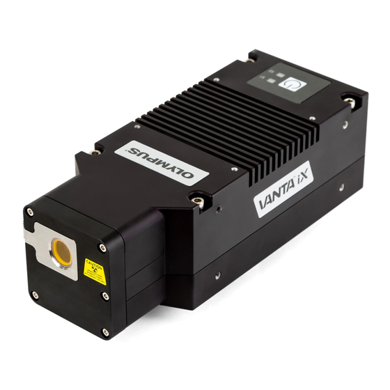
Vanta iX Family
X-Ray Fluorescence Analyzer
Installation Guide
This instruction manual contains essential information on how to use this Olympus product safely and effectively.
Before using this product, thoroughly review this instruction manual. Use the product as instructed.
Keep this instruction manual in a safe, accessible location.
International edition
10-019116-01EN — Rev. 2
January 2021
Advertisement
Chapters
Table of Contents
Troubleshooting

Subscribe to Our Youtube Channel
Related Manuals for Olympus Vanta iX Series


Summary of Contents for Olympus Vanta iX Series
- Page 1 10-019116-01EN — Rev. 2 January 2021 This instruction manual contains essential information on how to use this Olympus product safely and effectively. Before using this product, thoroughly review this instruction manual. Use the product as instructed. Keep this instruction manual in a safe, accessible location.
- Page 2 Olympus Scientific Solutions Americas, 48 Woerd Avenue, Waltham, MA 02453, USA Copyright © 2021 by Olympus. All rights reserved. No part of this publication may be reproduced, translated, or distributed without the express written permission of Olympus. This document was prepared with particular attention to usage to ensure the accuracy of the information contained therein, and corresponds to the version of the product manufactured prior to the date appearing on the title page.
-
Page 3: Table Of Contents
10-019116-01EN, Rev. 2, January 2021 Table of Contents List of Abbreviations ..................vii Labels and Symbols ................... 1 Important Information — Please Read Before Use ........5 Intended Use .......................... 5 Instruction Manual ........................ 5 Instrument Compatibility ..................... 6 Repair and Modification ....................... 6 Safety Symbols ........................ - Page 4 3.1.3 LED Connector and Cable Assembly ............38 3.1.4 Customer I/O Connector and Cable ............39 3.1.5 Olympus I/O Connector and Cable ............. 40 3.1.6 GPIO Breakout Board ..................40 Power Button ......................41 Mounting Instructions ....................42 4. Maintenance and Troubleshooting ............49...
- Page 5 10-019116-01EN, Rev. 2, January 2021 Measurement Window Replacement ..............49 4.1.1 Measurement Window Types ..............49 4.1.2 Measurement Window Removal ..............51 4.1.3 Measurement Window Replacement ............53 Troubleshooting ......................57 Appendix A: Specifications ................59 Appendix B: Radiation Profile ..............61 Profile Testing Information ..................
- Page 6 10-019116-01EN, Rev. 2, January 2021 Table of Contents...
-
Page 7: List Of Abbreviations
10-019116-01EN, Rev. 2, January 2021 List of Abbreviations ALARA as low as reasonably achievable EFUP environment-friendly use period GPIO general purpose input/output thermoluminescent dosimeter X-ray fluorescence List of Abbreviations... - Page 8 10-019116-01EN, Rev. 2, January 2021 viii List of Abbreviations...
-
Page 9: Labels And Symbols
Figure i-1 on page 1 and Figure i-2 on page 2. If any or all labels or symbols are missing or illegible, please contact Olympus. Rating label Figure i-1 Rating label location... -
Page 10: Figure I-2 Radiation Label Locations
10-019116-01EN, Rev. 2, January 2021 Figure i-2 Radiation label locations Labels and Symbols... -
Page 11: Table 1 Content Of The Rating Label
European Community. See the Compliance Statements for details. Contact your Olympus representative for more information. This device complies with Part 15 of the FCC Rules. Operation is subject to the following two conditions: (1) this... - Page 12 Table 1 Content of the rating label (continued) The KC marking is a declaration that this product conforms to all the applicable standards of South Korea. Contact your Olympus representative for more information. The MSIP code for the Vanta iX is the following: R-R-OYN- VANTAIX.
-
Page 13: Important Information - Please Read Before Use
Do not use the Vanta iX for any purpose other than its intended use. Instruction Manual This instruction manual contains essential information on how to use this Olympus product safely and effectively. Before using this product, thoroughly review this instruction manual. Use the product as instructed. -
Page 14: Instrument Compatibility
PC using an Ethernet connection. The unit derives its required DC input power from the AUX DC port or Power over Ethernet (PoE) port. CAUTION Always use equipment and accessories that meet Olympus specifications. Using incompatible equipment could cause equipment malfunction and/or damage, or human injury. -
Page 15: Safety Signal Words
10-019116-01EN, Rev. 2, January 2021 General warning symbol This symbol is used to alert the user to potential hazards. All safety messages that follow this symbol shall be obeyed to avoid possible harm or material damage. Radiation warning symbol This symbol is used to alert the user to the presence of potentially harmful ionizing radiation generated within the XRF or XRD analyzer. -
Page 16: Note Signal Words
10-019116-01EN, Rev. 2, January 2021 CAUTION The CAUTION signal word indicates a potentially hazardous situation. It calls attention to a procedure, practice, or the like that if not correctly performed or adhered to may result in minor or moderate personal injury, material damage, particularly to the product, destruction of part or all of the product, or loss of data. -
Page 17: Warnings
Otherwise, a malfunction or electric shock may result. WARNING Electrical Warnings If an unauthorized power supply cord is used to power the instrument, Olympus cannot guarantee the electrical safety of the equipment. Important Information — Please Read Before Use... -
Page 18: Equipment Disposal
Electronic Equipment (WEEE), this symbol indicates that the product must not be disposed of as unsorted municipal waste, but should be collected separately. Refer to your local Olympus distributor for return and/or collection systems available in your country. China RoHS China RoHS is the term used by industry generally to describe legislation implemented by the Ministry of Information Industry (MII) in the People’s Republic... - Page 19 10-019116-01EN, Rev. 2, January 2021 The China RoHS mark indicates the product’s Environment- Friendly Use Period (EFUP). The EFUP is defined as the number of years for which listed controlled substances will not leak or chemically deteriorate while in the product. The EFUP for the Vanta iX has been determined to be 15 years.
-
Page 20: Korea Communications Commission (Kcc)
10-019116-01EN, Rev. 2, January 2021 Korea Communications Commission (KCC) 이 기기는 업무용 환경에서 사용할 목적으로 적합성평가를 받은 기 기로서 가정용 환경에서 사용하는 경우 전파간섭의 우려가 있습니 다 . KC (South Korea Community) This device complies with the requirements of KN 61000-6-2 and KN 61000-6-4 concerning electromagnetic compatibility. -
Page 21: Ices-001 (Canada) Compliance
(1) This device may not cause harmful interference. (2) This device must accept any interference received, including interference that may cause undesired operation. Responsible party name: Olympus Scientific Solutions Americas Corp. Address: 48 Woerd Avenue, Waltham, MA 02453, USA Phone number:... -
Page 22: Code De La Santé Publique (France)
If the Vanta iX is not returned in its transport case, it could be damaged during shipping. Olympus reserves the right to void the warranty on instruments damaged while in transit if they are shipped without their transport case. Prior to returning any units, contact Customer Service to obtain the required RMA number(s) and any important shipping information. -
Page 23: Warranty Information
Olympus has no responsibility to provide any source code except the source code for certain software. http://www.olympus-ims.com/en/vanta-open-source-software/ Olympus does not respond to any inquiries related to any of the source codes obtained at the above URL. Warranty Information... -
Page 24: Technical Support
Technical Support Olympus is firmly committed to providing the highest level of customer service and product support. If you experience any difficulties when using our product, or if it fails to operate as described in the documentation, first consult the user’s manual, and then, if you are still in need of assistance, contact our After-Sales Service. -
Page 25: Introduction
10-019116-01EN, Rev. 2, January 2021 Introduction The Vanta iX X-ray fluorescence (XRF) analyzer is a energy dispersive X-ray fluorescence spectrometer that provides customizable, continual measurements on any surface. In an automated factory or processing plant, the system provides accurate chemical analysis for quality control applications. Main Applications The Vanta iX XRF analyzer delivers fast and precise identification and analysis of elements from magnesium to uranium (Mg to U), depending on the selected model... - Page 26 10-019116-01EN, Rev. 2, January 2021 Table 2 Analyzer features (continued) Feature Vanta iX C series Vanta iX M series Detector Large area performance IP56 IP56 IP rating Heat rating − − 10 °C to +50 °C 10 °C to +50 °C ...
-
Page 27: Safety Information
The Vanta iX XRF analyzer is a secure and dependable instrument when used according to Olympus recommended testing techniques and safety procedures. However, the Vanta iX produces ionizing radiation, and as such, it should only be used by individuals trained in correct operating techniques and authorized to use X- ray producing devices. -
Page 28: Radiation Safety Program
WARNING X-ray tube in the Vanta iX XRF analyzer can emit ionizing radiation. Prolonged exposure can cause serious illness or injury. It is the responsibility of Olympus customers to follow the operating instructions and safety recommendations in this manual and good radiation control practices. -
Page 29: Safety Features
• Do not use the Vanta iX if it is damaged. In such case, arrange for qualified personnel to perform a radiation safety test. Contact Olympus or its authorized service representative to repair any damage to the analyzer. Safety Features... -
Page 30: General Precautions
— Overheated electronics and other internal components Service Considerations Except as expressly noted in this document, do not service any Olympus product yourself. Opening or removing the external housings may expose you to electric shock and subject the instrument to mechanical damage, and it also voids the warranty. -
Page 31: Electrical Precautions
10-019116-01EN, Rev. 2, January 2021 IMPORTANT Any required servicing must be performed by Olympus or one of its authorized service representatives. Failure to observe this condition could result in voiding of the warranty. The exception to this rule is the replacement of a measurement ONLY window. -
Page 32: Indicators And Statuses
10-019116-01EN, Rev. 2, January 2021 The Ethernet cable has Power over Ethernet (PoE+) enabled and connects to an Ethernet network capable of providing 30 W input power. Safe and proper handling of cables and cords • Connect the power cords to a properly grounded and easily accessible power outlet. -
Page 33: Radiation Safety Training Recommendations
X-ray tubes. It is important to inform yourself about these rules. NOTE For the convenience of clients, Olympus has compiled a list of recommendations. These recommendations: • Provide generic guidance on the ALARA (as low as reasonably achievable) approach to radiation safety. -
Page 34: Dosimeters
10-019116-01EN, Rev. 2, January 2021 During operation, make sure that the Vanta iX remains under the direct control of a factory-trained, certified operator. Set and protect the login password for each user of any control system. Time, Distance, and Shielding Policies Operators should limit the amount of time they spend around the energized Vanta iX XRF analyzer, maximize their distance from the analyzer window, and shoot into high-density materials whenever possible. -
Page 35: Dosimeter Safety Program
IMPORTANT Dosimeter badges are required in some countries or regions, and are optional in others. Olympus recommends that all Vanta iX analyzer operators wear a dosimeter (badge or ring) for at least the first year of operating their analyzer(s). NOTE Every country (including each region, state, or province within a country) may have different regulations. -
Page 36: Dosimeter Suppliers
Beijing, China 86 10 6221 5635 1.10.5 Registration Requirements Contact Olympus for assistance with locating registration requirements. • United States of America and most other countries — Most states require some form of registration and generally require registration to be submitted within 30 days of receipt of the system. - Page 37 10-019116-01EN, Rev. 2, January 2021 — Customers are advised to consult their local Radiation Protection Authority for specific regulatory information. Typical Device Registration Information The following information is usually requested by a licensing agency: Purpose of device Industrial. Make sure that you inform the government registration office that the Vanta iX will NOT be used for radiography or medical use.
- Page 38 10-019116-01EN, Rev. 2, January 2021 • A copy of the installation manual for this equipment Chapter 1...
-
Page 39: Package Contents
WARNING If there is any damage to any of the components, do not attempt to use the Vanta iX XRF analyzer. Contact your local Olympus representative immediately. Case Contents The items in Table 4 on page 32 are included in the Vanta iX package. -
Page 40: Optional Accessories
USB cable (P/N: 10-013296-00) Ethernet cable (P/N: 10-013295-00) Radiation LED assembly (P/N: 10-014685-00) Olympus I/O cable (P/N: 10-013294-00) GPIO breakout board (P/N: 10-021277-00) Programming kit (P/N: Q0203718) Network port cap (P/N: 10-013297-00) ... -
Page 41: Analyzer Components
10-019116-01EN, Rev. 2, January 2021 Analyzer Components Table 6 on page 33 lists the Vanta iX XRF analyzer’s components. Table 6 Components Component key Vanta iX XRF analyzer 1 Probe 2 Measurement window plate 3 Measurement window ⑤ 4 Latch ①... - Page 42 10-019116-01EN, Rev. 2, January 2021 Chapter 2...
-
Page 43: Installation
XRF analyzer. Misuse of the Vanta iX could result in serious illness or injury. I/O Panel The I/O panel contains all of the Vanta iX I/O connectors (Figure 3-1 on page 36): DC power connector USB A connector Ethernet connector LED (radiation, light emitting diode) connector Customer I/O connector Olympus I/O connector Installation... -
Page 44: Power Connectors And Cables
10-019116-01EN, Rev. 2, January 2021 ① ④ ② ⑤ ③ ⑥ Figure 3-1 I/O panel connectors 3.1.1 Power Connectors and Cables The power connectors enable you to connect DC power to the Vanta iX. The DC power connector (10-18V DC) accepts a DC power cable to supply power to the instrument see Figure 3-2 on page 36. -
Page 45: Figure 3-3 Ethernet (Poe+) Cable
PoE+. NOTE You can control the Vanta iX on/off function through the Ethernet connection, or through the customer I/O connector, or through the Olympus I/O connector via discrete wiring by a PLC or similar type of controller. Installation... -
Page 46: Usb Connector And Data Cable
10-019116-01EN, Rev. 2, January 2021 3.1.2 USB Connector and Data Cable The USB connector ( ) enables you to connect a USB cable. Vanta iX XRF analyzers come standard with one USB A cable (Figure 3-4 on page 38). This cable provides the ability to connect to USB peripheral devices. -
Page 47: Customer I/O Connector And Cable
I/O connector via discrete wiring by a PLC or similar type of controller. Figure 3-6 CUST I/O cable NOTE The customer I/O cable and Olympus I/O cable are identical. However, the pinouts differ between the customer I/O connector and the Olympus I/O connector. Installation... -
Page 48: Olympus I/O Connector And Cable
GPIO board. Figure 3-7 OLY I/O cable NOTE The Olympus I/O cable and customer I/O cable are identical. However, the pinouts on the Olympus I/O connector differ from the customer I/O connector. 3.1.6 GPIO Breakout Board The Vanta iX comes standard with one general purpose input/output (GPIO) breakout board (Figure 3-8 on page 41). -
Page 49: Power Button
The connectors on the top half of the breakout board are intended for the standard Olympus I/O. The connectors on the bottom half of the breakout board are intended for customer configured I/O. The left side is intended for connection to the Vanta iX. -
Page 50: Mounting Instructions
10-019116-01EN, Rev. 2, January 2021 To power on the XRF analyzer Press and hold the power button ( ) for one second. To power off the XRF analyzer Press and hold the power button ( ) for one second. To power off the XRF analyzer under emergency conditions NOTE If the radiation LED remains illuminated or blinking, and you believe that the... -
Page 51: Figure 3-9 Vanta Ix Left Side
10-019116-01EN, Rev. 2, January 2021 Figure 3-9 Vanta iX left side Installation... -
Page 52: Figure 3-10 Vanta Ix Right Side
10-019116-01EN, Rev. 2, January 2021 Figure 3-10 Vanta iX right side Chapter 3... -
Page 53: Figure 3-11 Vanta Ix Top
10-019116-01EN, Rev. 2, January 2021 Figure 3-11 Vanta iX top Installation... -
Page 54: Figure 3-12 Vanta Ix Bottom
10-019116-01EN, Rev. 2, January 2021 Figure 3-12 Vanta iX bottom Chapter 3... -
Page 55: Figure 3-13 Vanta Ix Front
10-019116-01EN, Rev. 2, January 2021 Figure 3-13 Vanta iX front Installation... - Page 56 10-019116-01EN, Rev. 2, January 2021 Chapter 3...
-
Page 57: Maintenance And Troubleshooting
Immediately replace any broken or torn window. • For best results, regularly replace the window. • Make sure the replacement window matches your Vanta iX series and method. The correct window is required to achieve proper operation and accurate results. 4.1.1 Measurement Window Types Table 7 on page 50 describes the measurement window types. -
Page 58: Table 7 Measurement Window Types
10-019116-01EN, Rev. 2, January 2021 Table 7 Measurement window types Material Image Vanta iX series Part number Kapton 10-011890-00 mesh/reinforced prolene Prolene, 6µm 10-015963-00 CAUTION To avoid damage to the analyzer, comply with the instructions below: • Do not touch or damage any internal components. -
Page 59: Measurement Window Removal
Turn off the Vanta iX. IMPORTANT Olympus recommends that you remove the network cable before removing the measurement window to be sure that the Vanta iX cannot be remotely started. Locate the window faceplate latch at the front of the instrument (Figure 4-1 on page 51). -
Page 60: Figure 4-2 Latch Pulled Out
10-019116-01EN, Rev. 2, January 2021 Pull out the rear of the latch to release the tension on the faceplate (Figure 4-2 on page 52). Figure 4-2 Latch pulled out Pull out the front of the latch to fully open the faceplate latch (Figure 4-3 on page 52). -
Page 61: Measurement Window Replacement
10-019116-01EN, Rev. 2, January 2021 Alignment tab Figure 4-4 Faceplate alignment tab fully visible 4.1.3 Measurement Window Replacement The measurement window is attached by an adhesive to the back of the faceplate (Figure 4-5 on page 53). This procedure requires that you peel off the old window and place the new window. -
Page 62: Figure 4-6 Peeling The Window (Left) And Pulling It Off (Right)
10-019116-01EN, Rev. 2, January 2021 Figure 4-6 Peeling the window (left) and pulling it off (right) To replace the window Remove the window from its packaging and peel the backing material completely off the window (Figure 4-7 on page 54). IMPORTANT The back of the measurement window is coated with a sticky adhesive. -
Page 63: Figure 4-8 New Window Aligned With Faceplate
10-019116-01EN, Rev. 2, January 2021 Align and carefully press the window onto the faceplate (Figure 4-8 on page 55). IMPORTANT Handle the window by the edges to prevent contamination of the measurement area. Figure 4-8 New window aligned with faceplate Maintenance and Troubleshooting... -
Page 64: Figure 4-9 Orienting Faceplate With Latch And Probe Cutout
10-019116-01EN, Rev. 2, January 2021 Orient the faceplate with the latch and the cutout on the probe (Figure 4-9 on page 56). Probe cutout Latch Figure 4-9 Orienting faceplate with latch and probe cutout Slide the faceplate into the cutout on the probe, making sure the faceplate alignment tab is inserted into the tab slot (Figure 4-10 on page 56). -
Page 65: Troubleshooting
Vanta iX (Table 8 on page 57). If these measures do not restore the Vanta iX to full functionality, please contact Olympus After-Sales Service. When contacting a service center, please provide the instrument model, serial number, current software version, and a brief description of your issue. - Page 66 10-019116-01EN, Rev. 2, January 2021 Table 8 Troubleshooting guide (continued) Problem Possible solutions The analysis results do not • Test certified reference material. match with the expected • Ensure that the measurement window is values. clean and free of contamination. •...
-
Page 67: Appendix A: Specifications
Humidity: 10 % to 90 % relative humidity, noncondensing IP rating IP54 Operating system Linux Application software Olympus proprietary data acquisition and processing package USB interface USB 2.0 type A host port for accessories such as USB flash drives Specifications... -
Page 68: Table 10 Accessory Specifications
Ethernet connector with Power over Ethernet (PoE+) enabled RAD LED cable Includes an LED indicator Customer I/O cable Connects bi-directional signals to the GPIO board Olympus I/O cable Connects bi-directional signals to the GPIO board PoE+ network switch Supplies PoE+ PoE+ port injector... -
Page 69: Appendix B: Radiation Profile
10-019116-01EN, Rev. 2, January 2021 Appendix B: Radiation Profile The tables below represent upper bounds on the worst case maximum power and minimum beam filtration using a 316 stainless steel target. More specifically, the Vanta iX was operating at either 40 kV, 100 µA w/2 mm Al filter (model VIX-CW); or, 50 kV (model VIX-MR), 80 µA, 350 µm Cu filter. -
Page 70: Profile Testing Information
10-019116-01EN, Rev. 2, January 2021 Table 12 Maximum Leakage radiation measured at 50 kV in µSv/h Surveyed location Close 10 cm 30 cm Front 22.8 Left Side (front of scatter plane) 14.3 Right Side (front of scatter plane) Top (up to front cover seam) 27.6 Left Side (behind scatter plane) Right Side (behind scatter plane) -
Page 71: Figure B-1 Test Setup And Survey Diagram
10-019116-01EN, Rev. 2, January 2021 Top (up to front cover seam) Left side (behind scatter plane) Right side (behind scatter plane) Top (rear up to scatter plane) 10. Bottom (under the instrument) ① ⑤ ⑥ ③ ④ ② ② ⑨ ⑦... - Page 72 10-019116-01EN, Rev. 2, January 2021 Appendix B...
-
Page 73: Appendix C: Alloy Grade Libraries
User library #2 • The Residuals (tramp) settings NOTE Libraries are editable. However, Olympus does not recommend that users edit the Factory Grade library. Instead, copy the Factory Grade library to a user library, then make your edits. Residuals Settings Every Vanta iX XRF analyzer is shipped with Residuals (tramp) settings comprised of seven base alloys (Table 13 on page 66). -
Page 74: Table 13 Residuals Settings Base Alloys
10-019116-01EN, Rev. 2, January 2021 — Each sample is determined to be one of seven possible base alloys (Table 13 on page 66). — The analyzer applies the residual grade/base-specific residual limits from the matching residual grade. These residual or “alloy-base-specific” limits are applied when an element is detected in a specific grade. -
Page 75: Factory Grade Library: M And C Series
10-019116-01EN, Rev. 2, January 2021 Factory Grade Library: M and C Series Table 14 Cast aluminum alloys—M and C Series Table 15 Cobalt alloys—M and C Series AlnicoVIII Cobalt Elgiloy FSX-414 HS-1 HS-12 HS-188 HS-19 HS-21 HS-23 HS25-L605 HS-27 HS-3 HS-30 HS-31 HS-36... -
Page 76: Table 16 Copper Alloys-M And C Series
10-019116-01EN, Rev. 2, January 2021 Table 16 Copper alloys—M and C Series (continued) C 642 C 654 C 655 C 663 C 664 C 667 C 669 C 673 C 675 C 687 C 688 C 704 C 706 C 710 C 713 C 715 C 722... -
Page 77: Table 18 Low-Alloy And Tool Steels-M And C Series
10-019116-01EN, Rev. 2, January 2021 Table 17 Nickel alloys—M and C Series (continued) Monel411 MuMetal Nim101 PWA1480 PWA1484 Rene125 Rene142 Rene220 Rene77 Rene80 Rene95 Supertherm Udimet700 B 1900 B-1900 Hf C-1023 GMR235 Alloy D Duranickel Permanickel GH99 Table 18 Low-alloy and tool steels—M and C Series 1 1-4 Cr 2 1-4 Cr 5 Cr... -
Page 78: Table 20 Titanium Alloys-M And C Series
10-019116-01EN, Rev. 2, January 2021 Table 19 High-alloy and stainless steels—M and C Series (continued) Ni-hard#1 Ni-hard#4 Ni-Resist1 Ni-Resist2 Ni-Resist3 Ni-Resist4 Ni-Resist5 Ni-Span902 Nitronic32 Nitronic33 Nitronic40 Nitronic50 Nitronic60 RA85H ZeCor Zeron100 Table 20 Titanium alloys—M and C Series CP Ti Gr 1 CP Ti Gr 2 CP Ti Gr 4 CP Ti Gr 11... -
Page 79: Table 22 Wrought Aluminum Alloys-M And C Series
10-019116-01EN, Rev. 2, January 2021 Table 22 Wrought aluminum alloys—M and C Series (continued) 2024 2025 2030 2031 2034 2036 2090 2091 2094 2095 2097 2111 2117 2124 2195 2197 2214 2218 2219 2297 2519 2618 3002 3003 3004 3005 3009 3010 3011... - Page 80 10-019116-01EN, Rev. 2, January 2021 Appendix C...
-
Page 81: List Of Figures
10-019116-01EN, Rev. 2, January 2021 List of Figures Figure i-1 Rating label location .................... 1 Figure i-2 Radiation label locations ..................2 Figure 1-1 Dosimeters — Various styles ................26 Figure 3-1 I/O panel connectors ..................36 Figure 3-2 DC power cable ....................36 Figure 3-3 Ethernet (PoE+) cable .................. - Page 82 10-019116-01EN, Rev. 2, January 2021 List of Figures...
-
Page 83: List Of Tables
10-019116-01EN, Rev. 2, January 2021 List of Tables Table 1 Content of the rating label ..................3 Table 2 Analyzer features ....................17 Table 3 Dosimeter suppliers ....................28 Table 4 Case contents ......................32 Table 5 Optional accessories ....................32 Table 6 Components ...................... - Page 84 10-019116-01EN, Rev. 2, January 2021 List of Tables...
-
Page 85: Index
10-019116-01EN, Rev. 2, January 2021 Index components, analyzer 33 AC power adaptor 36 accessories, specifications 60 DANGER signal word 7 administration, safety 24 DC power cable 23 Alloy Grade libraries 65 disposal, equipment 10 analyzer dosimeter applications 17 safety program 27 components 33 suppliers 28 indicators and statuses 24... - Page 86 20 information notes X-ray tubes 20 IMPORTANT 8 NOTE 8 TIP 8 Olympus technical support 16, 57 safety 7 open source software 14 CAUTION 8 DANGER 7 packing and return shipping 14 WARNING 7...
- Page 87 10-019116-01EN, Rev. 2, January 2021 suppliers, dosimeter 28 general 7 support information, technical 16, 57 radiation 7 symbols 1 shock hazard 7 CE 3 warnings FCC 3 electrical 9 Korean standard 4 general 9 RCM (Australia) 4 warranty information 15 RoHS 4, 11 waste electrical and electronic equipment 10 safety 6...
- Page 88 10-019116-01EN, Rev. 2, January 2021 Index...
Need help?
Do you have a question about the Vanta iX Series and is the answer not in the manual?
Questions and answers