Table of Contents
Advertisement
Revision AJ
September 2008
Copyright © 2002-2008
by California Instruments.
All rights reserved.
P/N 7003-960
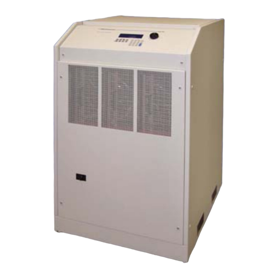
MX Series
AC and DC Power Source
User Manual
Series I / Series II
TEL: +1 (858) 677-9040
FAX: +1 (858) 677-0940
Email:
sales@calinst.com
Web Site:
http://www.calinst.com
CompuMess Elektronik GmbH • Lise-Meitner-Str. 1 • D-85716 Unterschleißheim
Telefon (089) 32 15 01 - 0 • Telefax (089) 32 15 01 - 11 • www.compumess.de • www.netzteile.de
Advertisement
Table of Contents


Need help?
Do you have a question about the MX30-1 and is the answer not in the manual?
Questions and answers