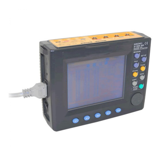
Hioki 3169-20 Instruction Manual
Clamp on power hitester
Hide thumbs
Also See for 3169-20:
- Instruction manual (216 pages) ,
- Quick start manual (40 pages) ,
- Quick start manual (38 pages)
Table of Contents
Advertisement
Advertisement
Table of Contents

Related Manuals for Hioki 3169-20


Summary of Contents for Hioki 3169-20
- Page 1 INSTRUCTION MANUAL 3169-20/21 CLAMP ON POWER HiTESTER...
-
Page 3: Table Of Contents
Contents Contents Introduction ..............1 Standard Accessories and Options ......1 Safety Notes ..............4 Usage Notes ..............7 1 Overview Product Overview ..........13 Features ............14 2 Parts Names Instrument Labels and Functions ..... 18 Screen Names and Display Elements ....22 2.2.1 Screen Configuration .........22 2.2.2 Common Display ..........23 2.2.3 On-Screen Indicators .........24... - Page 4 Contents 4 Connecting to Lines to be Measured Connection Procedure ........35 Connection Methods ........36 4.2.1 Displaying the Wiring Diagram ......36 4.2.2 Basic Wiring for Single-Circuit Measurement ..39 4.2.3 Wiring for Multiple-Circuit Measurement ...45 4.2.4 Connection to a Line to Be Measured ....48 4.2.5 Checking the Wiring ..........49 Measurement Range ........
- Page 5 Contents 5.3.7 Setting the Medium to which the Screen is to be Copied ...............78 Setting on the Save/Print Items Setting Screen (SAVE, PRINT ITEMS) ........79 5.4.1 Checking the number of output data items and Storable Time ............79 5.4.2 Setting Normal Measurement-Data Output Items ................80 5.4.3 Setting Integrated power and Demand Measurement-data Output Items .......81...
- Page 6 Contents Performing Demand Measurement ....104 Measuring Harmonic ........105 6.7.1 Displaying a Harmonic List ......105 6.7.2 Displaying a Harmonic Graph ......108 Displaying on a Zoom Screen ......113 Holding Displayed Measurement Data ... 114 7 Loading and Saving Settings and Measured Data Types of Files ..........
- Page 7 ................ 151 10.2 Functions of the External Input/Output Terminal ................ 152 10.3 Controlling Multiple Units of the 3169-20/21 .. 155 11 Using D/A Output (3169-21 only) 11.1 Connecting the D/A Output Terminal ..... 157 11.2 Setting D/A Output ......... 159 11.2.1 Setting D/A Output Items .........159...
- Page 8 Contents 14 Maintenance and Service 14.1 Cleaning and Storage ........189 14.2 Repair and Servicing ........190 14.3 Instrument Disposal ........192 Appendix Power Measurement by the 2 Power-Meter Method and U3/I3 Measurement Theory (3P3W2M mode) ..195 Headers of Output Data ........... 197 Harmonic Phase Angles ..........
-
Page 9: Introduction 1
Introduction Thank you for purchasing the HIOKI “3169-20/21 CLAMP ON POWER HiTESTER”. To obtain maximum performance from the product, please read this manual first, and keep it handy for future reference. • Refer to the Quick Start Manual provided with this device. - Page 10 Options Clamps Voltage output type: • 9660 CLAMP ON SENSOR (100 A rms rating) • 9661 CLAMP ON SENSOR (500 A rms rating) • 9667 FLEXIBLE CLAMP ON SENSOR (5000 A rms rating) • 9669 CLAMP ON SENSOR (1000 A rms rating) •...
- Page 11 • Before using the product the first time, verify that it operates nor- mally to ensure that the no damage occurred during storage or shipping. If you find any damage, contact your dealer or Hioki representative. • Before using the product, make sure that the insulation on the 9438-03 VOLTAGE CORD is undamaged and that no bare con- ductors are improperly exposed.
-
Page 12: Safety Notes 4
Safety Notes This product is designed to conform to IEC 61010 Safety Standards, and has been thoroughly tested for safety prior to shipment. However, mishandling during use could result in injury or death, as well as damage to the product. Be cer- tain that you understand the instructions and precautions in the manual before use. - Page 13 The following symbols in this manual indicate the relative impor- tance of cautions and warnings. Indicates that incorrect operation presents an extreme hazard that could result in serious injury or death to the user. Indicates that incorrect operation presents a signifi- cant hazard that could result in serious injury or death to the user.
- Page 14 Measurement categories (Overvoltage categories) This product conforms to the safety requirements for CAT III mea- surement products. To ensure safe operation of measurement products, IEC 61010 establishes safety standards for various electrical environments, categorized as CAT I to CAT IV, and called measurement catego- ries.
-
Page 15: Usage Notes
Usage Notes Follow these precautions to ensure safe operation and to obtain the full benefits of the various functions. To avoid electric shock Do not get wet. • Do not allow the product to get wet, and do not use it when your hands are wet. - Page 16 Setting up the 3169-20/21 Avoid the follow- • This product is designed for indoor use, and operates reliably ing: from 0°C to 40°C. • Do not store or use the product where it could be exposed to direct sunlight, high temperature or humidity, or condensation.
- Page 17 • The current input terminals of the 3169-20/21 are not insulated. To avoid the risk of electric shock, only use the specified...
- Page 18 Handling the cords • Keep in mind that, in some cases, conductors to be measured may be hot. • To avoid damaging the power cord, grasp the plug, not the cord, when unplugging the cord from the power outlet. • To avoid damaging the voltage cords or clamp sensor cables, do not bend or pull near their ends.
- Page 19 • To avoid damage to the product, do not short-circuit the output terminal and do not input voltage to the output terminal. • Voltage input terminals U , and U are common to the N ter- minal and are not insulated. To avoid the risk of electric shock, do not touch the terminals.
- Page 20 Measurement values • To ensure measurements are precise, warm up the device for at least 30 minutes after plugging it in. • This device is designed to measure commercial power lines with a frequency of 50 or 60 Hz. It cannot measure power lines of other frequencies or power lines where the waveforms are controlled using an inverter.
-
Page 21: Overview 13
Product Overview Overview 1.1 Product Overview The 3169-20/21 CLAMP ON POWER HiTESTER is a clamp-on wattmeter designed to measure lines ranging from a single-phase line to a three-phase 4-wire line. The 3169-20/21 can measure demand and harmonics, which are important for power management, as well as such basic measurements of voltage, current, power, power factor, and integrated power (watt- hours). -
Page 22: Features 14
Capable of integrating different polarities independently, such as active power consumption/regeneration and reactive power lag/lead. Three-Voltage, Three-Current Measurement Capable of measuring 3-voltage, 3-current when the 3169-20/21 is connected to a three-phase, 3-wire line. Harmonic Measurement Capable of measuring the harmonics of a power line simultaneously with integrated power (watt-hour) measurement. - Page 23 Features RS-232C Interface The 3169-20/21 includes an RS-232C interface as standard equipment. The instrument is connected to a PC by the interface, and is used for automated measurement. High-Speed D/A Output (3169-21 only) The 3169-21 features D/A output for 4-channel, high-speed analog output.
- Page 24 Features...
-
Page 25: Parts Names
Parts Names ❖4 "Connecting to Lines to be Measured" (page 35) ❖11 "Using D/A Output (3169-21 only)" (page 157) Recorder, logger ❖10 "Using the External Input/ Output Terminal" (page 151) D/A output (3169-21) ❖9 "Using the Instrument with EXT I/O a Computer"... - Page 26 2.1 Instrument Labels and Functions 2.1 Instrument Labels and Functions Front Panel Display 5.7-inch STN LCD Cursor key Function (F1-F5) keys These keys move the cursor Selects or switches the screens and on the screen. setting items.
- Page 27 2.1 Instrument Labels and Functions Front Panel Enhanced View MEASURE key Switches to a screen that displays measurements. SET UP key Switches to a screen that displays settings. FILE key Used to work on files. I RANGE key Sets the current measurement range for the circuit to be measured on-screen.
- Page 28 2.1 Instrument Labels and Functions Top Panel Voltage Input terminals Connect the supplied 9438-03 VOLTAGE CORD. Black Red Yellow Blue CH1 CH2 CH3 CH4 Current Input terminals Connect an optional clamp-on sensor. Left Panel KEY LOCK switch Contrast Control Knob Sliding this switch in the direction of the ar- (CONTRAST) row disables all key operation except the...
- Page 29 2.1 Instrument Labels and Functions Right Panel RS-232C Interface connector PC Card slot Connects to a PC or printer using an A PC Card can be RS-232C cable. inserted here. D/A Output Terminal (D/A OUT) Installed in the 3169-21 only. Connects the supplied 9441 connection cable.
-
Page 30: Screen Names And Display Elements 22
2.2 Screen Names and Display Elements 2.2 Screen Names and Display Elements 2.2.1 Screen Configuration The screens are divided into three basic types: measurement screens, setting screens, and file screens. Each screen is selected using three panel keys: , and MEASURE SET UP FILE... -
Page 31: Common Display
2.2 Screen Names and Display Elements 2.2.2 Common Display This section of the screen shows information common to all mea- surement screens (except the zoom screen and the wiring diagram screen). Common Display Time Range Wiring No. of circuits Synchronization method Interval Time... - Page 32 2.2 Screen Names and Display Elements 2.2.3 On-Screen Indicators Goes on when the reactive-power-meter method is Goes on when the displayed measurement is held. Goes on when the medium for saving data is set to PC card. Flashes when the PC card is accessed. Goes on when the medium for saving data is set to internal memory.
-
Page 33: Measurement Preparations
3.1 Connection Procedure Yellow Measurement Preparations Please read the Usage Notes (page 7) before setting up this instrument. 3.1 Connection Procedure Refer to the indicated reference items before installing and con- necting. Connecting the Power Cord ❖(page 26) Connecting the Voltage Cords ❖(page 27) Connecting a Clamp-on Sensor (Apply the input cord labels) - Page 34 3.2 Connecting the Power Cord 3.2 Connecting the Power Cord • Before turning the product on, make sure the source volt- age matches that indicated on the product's power connec- tor. Connection to an improper supply voltage may damage the product and present an electrical hazard. •...
-
Page 35: Connecting The Voltage Cords
Cords not being used for measurement should be disconnected. Connecting the voltage cords to the instrument Connect the voltage cables to the voltage input termi- nals of the 3169-20/21. The number of voltage cables required depends on the line to be measured. Insert plugs all the Fully insert the cable plug. - Page 36 3.3 Connecting the Voltage Cords Voltage cords and measurement lines Single-phase 2-wire (1P2W) Measurement Line type Black Voltage input terminals Single-phase 3-wire (1P3W) Black Red Yellow Three-phase 3-wire (3P3W2M) Black Red Yellow Three-phase 3-wire (3P3W3M) Yellow Blue Three-phase 4-wire (3P4W, 3P4W4I) Black Red Blue Yellow...
-
Page 37: Using A Clamp-On Sensor (Option)
• To prevent damage to the product and sensor, never con- nect or disconnect a sensor while the power is on. • The current input terminals of the 3169-20/21 are not insu- lated. To avoid the risk of electric shock, only use the spec- ified optional clamp-on sensor. - Page 38 3.4 Using a Clamp-On Sensor (Option) 9661 CLAMP ON SENSOR Rated primary current 500 A AC Output voltage 1 mVAC/A ° Maximum permissible input 550 A continuous (at 45 to 66 Hz, 50 Amplitude accuracy ±0.3% rdg. ±0.01% f.s. (f.s.=500 A, 45 to 66 Hz) °...
-
Page 39: Connecting A Clamp-On Sensor
At each end of the cable, apply the input cord labels having the same color as the current input terminal to which it is to be connected. 3169-20/21 Current BNC plug slots input terminal connector guide Align the slots in the BNC plug with... - Page 40 3.4 Using a Clamp-On Sensor (Option) Clamp-on sensors and measurement lines Single-phase 2-wire Single-phase 3-wire Measurement Line type (1P2W) (1P3W) Red Yellow Current Input terminals Three-phase 3-wire Three-phase 3-wire (3P3W2M) (3P3W3M) Red Yellow Red Yellow Blue Three-phase 4-wire Three-phase 4-wire (3P4W) (3P4W4I) Yellow...
-
Page 41: Turning The Power On/Off
(Self-test screen) Version No. Internal mem- ory test result Powering Off Turn the POWER switch OFF ( Power switch Off: If an error occurs during selt-testing, the instrument may be dam- aged. Contact your dealer or HIOKI representative. - Page 42 3.5 Turning the Power On/Off...
-
Page 43: Connecting To Lines To Be Measured
❖3.4 Using a Clamp-On Sen- input terminals. sor (Option) (page 29) ❖3.5 Turning the Power On/Off Turn on ( | ) the 3169-20/21. (page 33) Select the wiring diagram screen on the measurement screen to view the wiring SCREEN... -
Page 44: Connection Methods
4.2 Connection Methods 4.2 Connection Methods 4.2.1 Displaying the Wiring Diagram Press the key to display the measurement screen. MEASURE Press the (SCREEN) key to display the selection window. SCREEN Select "WIRING DIAGRAM" by using the cursor key. Press the (select) key;... - Page 45 4.2 Connection Methods Wiring diagram screen (1) Set the Wiring Method. Press the (WIRING) key to display the selection window. WIRING 1P2W Measurement of a single-phase, 2-wire line 1P3W Measurement of a single-phase, 3-wire line 3P3W2M Measurement of a three-phase, 3-wire line (by the two- power-meter method) Select this method to measure three-phase power by measuring the current at two positions only.
- Page 46 4.2 Connection Methods (2) Set the Number of Circuits (when measuring multiple circuits). Press the (CIRCUIT) key to display the selection window. CIRCUIT 1P2W 1 (1 circuit), 2 (2 circuits), 3 (3 circuits), 4 (4 circuits) 1P3W 1 (1 circuit), 2 (2 circuits) 3P3W2M 1 (1 circuit), 2 (2 circuits) 3P3W3M,3P4W,...
-
Page 47: Basic Wiring For Single-Circuit Measurement
4.2 Connection Methods 4.2.2 Basic Wiring for Single-Circuit Measurement Single-phase 2-wire (1P2W) Black Face the arrow toward the Load Wiring diagram screen Wiring check screen (Power factor: 0.87) ❖ 4.2.5 Checking the Wiring (page 49) - Page 48 4.2 Connection Methods Single-phase 3-wire (1P3W) Black Yellow Face the arrow toward the Load Wiring diagram screen Wiring check screen (Power factor: 0.87) ❖ 4.2.5 Checking the Wiring (page 49)
- Page 49 4.2 Connection Methods Three-phase 3-wire (3P3W2M) 2-Power-Meter Method Black Yellow Face the arrow toward the Load Wiring diagram screen Wiring check screen (Power factor: 1) ❖ 4.2.5 Checking the Wiring (page 49)
- Page 50 4.2 Connection Methods Three-phase 3-wire (3P3W3M) 3-Power-Meter Method Yellow Blue Not con- nected Face the arrow toward the Load Wiring diagram screen Wiring check screen (Power factor: 1) ❖ 4.2.5 Checking the Wiring (page 49)
- Page 51 4.2 Connection Methods Three-phase 4-wire (3P4W) N: Neutral conductor Yellow Blue Black Face the arrow toward the Load Wiring diagram screen Wiring check screen (Power factor: 0.87) ❖ 4.2.5 Checking the Wiring (page 49)
- Page 52 4.2 Connection Methods Three-phase 4-wire (3P4W4I) Neutral Current Measurement N: Neutral conductor Yellow Blue Black Face the arrow toward the Load Wiring iagram screen The connection for neutral current I4 is not checked. Wiring check screen (Power factor: 0.87) ❖ 4.2.5 Checking the Wiring (page 49)
-
Page 53: Wiring For Multiple-Circuit Measurement
4.2 Connection Methods 4.2.3 Wiring for Multiple-Circuit Measurement • One 3169-20/21 unit can measure multiple circuits of the same voltage system (same transformer). • The wiring mode is common to all circuits. • Measurements of the current channels will not be zeroed when the device is not connected to the clamp-on sensor. - Page 54 4.2 Connection Methods Single-phase 3-wire, 2circuits ( 1P3W X 2 Black Yellow Wiring diagram screen Face the arrow toward the Load changes the circuit to display. Wiring check screen (Power factor: 0.87) ❖ 4.2.5 Checking the Wiring (page 49)
- Page 55 4.2 Connection Methods Three-phase 3-wire, 2circuits (3P3W2M X 2) 2-Power-Meter Method Black Yellow Wiring diagram screen Face the arrow toward the Load changes the circuit to display. Wiring check screen (Power factor: 1) ❖ 4.2.5 Checking the Wiring (page 49)
-
Page 56: Connection To A Line To Be Measured
4.2 Connection Methods 4.2.4 Connection to a Line to Be Measured Connect the voltage cables and clamp-on sensor to the line to be measured, while referring to the wiring diagram. To ensure correct measurement results, follow the instrument setup and wiring instructions precisely. Connecting the Voltage Cords to the Lines to be Measured (Example) Clip securely to metal parts such as connection... -
Page 57: Checking The Wiring
4.2 Connection Methods 4.2.5 Checking the Wiring Check to see if the 3169-20/21 is correctly connected to the line to be measured. Press the key to display the measurement screen. MEASURE Press the (SCREEN) key to display the selection window. - Page 58 4.2 Connection Methods (1) Display the Screen of Another Circuit (when measuring multiple circuits). Indicates the circuit No. Pressing the (CIRCUIT) key repeatedly changes the circuit on CIRCUIT the screen as follows: " "→" "→" "→" " Circuit 1 Circuit 2 Circuit 3 Circuit 4 (Up to Circuit 2 when 1P3W or 3P3W2M is selected.)
- Page 59 4.2 Connection Methods (3) Change the Current Range. Pressing the key repeatedly changes the range for the cir- I Range cuit on the screen as follows: When using the "5 A"→"10 A"→"50 A"→"100 A" 9660/9695-03: When using the "5 A"→"10 A"→"50 A"→"100 A"→"500 A"...
- Page 60 The voltage input • Do the voltage clips grip the wires properly? is NG. • Is the voltage cable properly inserted into the voltage input terminal of the 3169-20/ The current input • Is the clamp-on sensor securely inserted is NG.
-
Page 61: Measurement Range
4.3 Measurement Range 4.3 Measurement Range This unit is not equipped with an automatic range selection function, therefore you must select the operation ranges. The display and effective measurement ranges (ranges where accuracy is cer- tain) of measurement ranges are as follows. Voltage Range Effective measurement range Effective measurement range... - Page 62 4.3 Measurement Range Current Range Display range 5.5 kA 5 kA Effective measurement range 0.02 kA 0.25 kA 6.5 kA 1.1 kA 1 kA Effective measurement range 0.004 kA 0.05 kA 1.3 kA 0.001 kA 0.01 kA 0.1 kA 1 kA 10 kA 550 A 500 A...
-
Page 63: Setting Procedure
5.1 Setting Screen Setting Procedure 5.1 Setting Screen Press the key to display the setting screen. SET UP NEXT Pressing the (NEXT SCR) key or key repeatedly SET UP switches the screen as follows: MEASUREMENT DATA OUTPUT SAVE, PRINT ITEMS SYSTEM D/A OUTPUT (3169-21 only) - Page 64 5.2 Setting on the Measurement Setting Screen (MEASUREMENT) 5.2 Setting on the Measurement Setting Screen (MEASUREMENT) The measurement setting screen enables the items below to be set. • Wiring method • Number of circuits to be measured • Synchronization method •...
-
Page 65: Setting The Wiring Method
SET UP NEXT Press the (NEXT SCR) key to display the measurement setting screen. (3169-20: SET UP 1/4, 3169-21: SET UP 1/5) Move the cursor to " ." WIRING Press the (change) key to display the selection window. - Page 66 X 3 (3 circuits), X 4 (4 circuits) 1P3W X 1 (1 circuit), X 2 (2 circuits) 3P3W2M X 1 (1 circuit), X 2 (2 circuits) 3P3W3M,3P4W, X 1 (1 circuit) only 3P4W4I The 3169-20/21 can measure multiple circuits of the same voltage system (same transformer).
-
Page 67: Setting The Synchronization Method
What is PLL? PLL stands for "Phase Locked Loop" and is a phase synchroniza- tion circuit. The 3169-20/21 uses PLL to generate a frequency syn- chronized with the fundamental wave (50/60 Hz) and multiplied by 128, to sample input waveforms of voltage and current. If there is no PLL input (PLL source), there is no means of sampling input waveforms, and calculation cannot be performed. -
Page 68: Setting The Reactive-Power-Meter Method
SET UP NEXT Press the (NEXT SCR) key to display the measurement setting screen. (3169-20: SET UP 1/4, 3169-21: SET UP 1/5) Move the cursor to " ." VAR METHOD Use the function keys to set whether to use the reactive-power- meter method. - Page 69 5.2 Setting on the Measurement Setting Screen (MEASUREMENT) What is the Reactive-power-meter method? • The reactive-power-meter method is used to measure reactive power directly from the voltage and current, like a reactive power meter installed for large power consumers. • With some voltage and current waveforms, reactive power, apparent power, and power factor measurements may vary depending on the reactive-power-meter setting.
-
Page 70: Setting The Display Average Times
Press the key to display the setting screen. SET UP NEXT Press the (NEXT SCR) key to display the measurement setting screen. (3169-20: SET UP 1/4, 3169-21: SET UP 1/5) Move the cursor to " ." AVERAGE TIMES change Press the (change) key to display the selection window. -
Page 71: Setting The Voltage Range
SET UP NEXT Press the (NEXT SCR) key to display the measurement setting screen. (3169-20: SET UP 1/4, 3169-21: SET UP 1/5) Move the cursor to " ." VOLTAGE RANGE Set the voltage range by using the function keys as follows: (Select a range from 150 V, 300 V, and 600 V.) -
Page 72: Setting The Vt Ratio (Pt Ratio)
NEXT Press the (NEXT SCR) key to display the measurement setting screen. (3169-20: SET UP 1/4, 3169-21: SET UP 1/5) Move the cursor to the " " digit to be changed. Set the VT ratio by using the function keys as follows: (Cursor : Moves left to next digit;... -
Page 73: Setting The Current Range
SET UP NEXT Press the (NEXT SCR) key to display the measurement setting screen. (3169-20: SET UP 1/4, 3169-21: SET UP 1/5) Move the cursor to " " of the circuit to be CURRENT RANGE changed. -
Page 74: Setting The Ct Ratio
NEXT Press the (NEXT SCR) key to display the measurement setting screen. (3169-20: SET UP 1/4, 3169-21: SET UP 1/5) Move the cursor to the digit of " " of the circuit to be changed. Set the CT ratio for each circuit by using the function keys. -
Page 75: Setting The Clamp-On Sensor
SET UP NEXT Press the (NEXT SCR) key to display the measurement setting screen. (3169-20: SET UP 1/4, 3169-21: SET UP 1/5) Move the cursor to " " of the circuit to be changed. SENSOR Press the (change) key to display the selection window. - Page 76 5.3 Setting on the Data Output Setting Screen (DATA OUTPUT) 5.3 Setting on the Data Output Setting Screen (DATA OUTPUT) The data output setting screen allows setting of the following items. • Time-series measurement start method • Time-series measurement ending method •...
-
Page 77: Setting The Time-Series Measurement Start Method
SET UP NEXT Press the (NEXT SCR) key to display the data output setting screen. (3169-20: SET UP 2/4, 3169-21: SET UP 2/5) Move the cursor to " ." MEAS. START Set the time-series measurement start method using the function MANUAL keys. - Page 78 AUTO Set the start time to any subsequent time. If the set measurement start time has already expired when the key is pressed, the 3169-20/21 displays an error START/STOP message and starts measurement by the "Just" start method, which commences measurement at the optimal time.
-
Page 79: 5.3.2 Setting Time-Series Measurement Stop Method
SET UP Press the (NEXT SCR) key to display the data output setting NEXT screen. (3169-20: SET UP 2/4, 3169-21: SET UP 2/5) Move the cursor to " ." MEAS. STOP Set the time-series measurement stop method using the function MANUAL keys. - Page 80 5.3 Setting on the Data Output Setting Screen (DATA OUTPUT) Set the Time-Series Measurement Stop Time (when the stop method is set to Time). Move the cursor to the digit to be changed in the measurement stop date and time. Set the measurement stop time using the function keys.
- Page 81 5.3 Setting on the Data Output Setting Screen (DATA OUTPUT) Set the Timer (when the stop method is set to Timer). Move the cursor to the digit of the timer setting to be changed. Set the timer using the function keys. (Cursor : Moves left to next digit;...
-
Page 82: Setting Interval
• When the interval is 30 seconds or less, harmonic measure- ment-data output and printer output are not available. • When a short-term interval is selected, the 3169-20/21 outputs the instantaneous values of normal measurement only. The file will be in binary format and must be converted to a text file to be read into a generally available spreadsheet software. -
Page 83: Setting Medium For Saving Data
Set the medium for saving data using the function keys. CARD MEMORY When the PC card is selected, if a PC card is not installed or the 3169-20/21 fails to write data onto the PC card, the data will be stored in the internal memory as backup data. -
Page 84: Setting The Data File Name
Backspace (deletes the inputted character) enter enter Accepts the file name entry cancel Exits the file name input window unchanged cancel If no file name is set, the 3169-20/21 will automatically name the file. ❖ 7.1 Types of Files (page 115) - Page 85 SET UP Press the (NEXT SCR) key to display the data output setting NEXT screen. (3169-20: SET UP 2/4, 3169-21: SET UP 2/5) Move the cursor to " ." RS CONNECTION Use the function keys to set the device to be connected to the RS- 232C interface (Default: PC).
-
Page 86: Copied
SET UP NEXT Press the (NEXT SCR) key to display the data output setting screen. (3169-20: SET UP 2/4, 3169-21: SET UP 2/5) Move the cursor to " ." DISPLAY COPY Use the function keys to set the medium to which the screen is to CARD be copied. -
Page 87: Setting On The Save/Print Items Setting Screen
(xxx days: xx hours: xx minutes: xx seconds) Press the key to display the setting screen. SET UP NEXT Press the (NEXT SCR) key to display the save/print items set- ting screen. (3169-20: SET UP 3/4, 3169-21: SET UP 3/5) -
Page 88: Setting Normal Measurement-Data Output Items
SET UP Press the (NEXT SCR) key to display the save/print items set- NEXT ting screen. (3169-20: SET UP 3/4, 3169-21: SET UP 3/5) Move the cursor to " ." NORM. MEAS Press the (ON) key to turn ON normal measurement. -
Page 89: Setting Integrated Power And Demand Measurement-Data Output Items
SET UP Press the (NEXT SCR) key to display the save/print items set- NEXT ting screen. (3169-20: SET UP 3/4, 3169-21: SET UP 3/5) Move the cursor to " ." INTEG. & DEM. Press the (ON) key to turn ON the integrated power/demand measurement data. -
Page 90: Setting Harmonic Measurement-Data Output Items
SET UP NEXT Press the (NEXT SCR) key to display the save/print items set- ting screen. (3169-20: SET UP 3/4, 3169-21: SET UP 3/5) Move the cursor to " ." HARMONIC Press the (ON) key to turn ON harmonic measurement. - Page 91 5.4 Setting on the Save/Print Items Setting Screen (SAVE, PRINT ITEMS) (2) Set the Details of Harmonic Measurement-data Output. Press the (Detail Setting) key on the save/print items setting DETAILS screen to display the harmonic output detail setting screen. Turn the output of each piece of data ON/OFF using the cursor and function keys.
- Page 92 5.4 Setting on the Save/Print Items Setting Screen (SAVE, PRINT ITEMS) Select Order for Output. Move the cursor to " ." ORDER Set orders using the function keys. EVEN SELECT When (SELECT) is selected Move the cursor to the order of the data to be output. Turn data output ON/OFF using function keys.
- Page 93 5.5 Setting on the System Setting Screen 5.5 Setting on the System Setting Screen The system setting screen allows setting of the following items: • Total harmonic distortion (THD) calculation method • Harmonic order for display • RS-232C • LCD backlight •...
-
Page 94: Setting The Thd Calculation Method
SET UP Press the (NEXT SCR) key to display the system setting NEXT screen. (3169-20: SET UP 4/4, 3169-21: SET UP 4/5) Move the cursor to " ." Set the THD calculation method using the function keys. THD-F... - Page 95 SET UP NEXT Press the (NEXT SCR) key to display the system setting screen. (3169-20: SET UP 4/4, 3169-21: SET UP 4/5) Move the cursor to " ." HARM. DISP. ORD Use the function keys to set the harmonic orders to be displayed...
-
Page 96: Setting The Rs-232C
Press the key to display the setting screen. SET UP Press the (NEXT SCR) key to display the system setting NEXT screen. (3169-20: SET UP 4/4, 3169-21: SET UP 4/5) Move the cursor to " ." BAUD RATE change Press the (change) key to display the selection window. -
Page 97: Setting The Lcd Backlight
SET UP Press the (NEXT SCR) key to display the system setting NEXT screen. (3169-20: SET UP 4/4, 3169-21: SET UP 4/5) Move the cursor to " ." BACKLIGHT Set the LCD backlight using the function keys. - Page 98 SET UP Press the (NEXT SCR) key to display the system setting NEXT screen. (3169-20: SET UP 4/4, 3169-21: SET UP 4/5) Move the cursor to " ." BEEP SOUND Set the beep sound using the function keys.
-
Page 99: Setting The Id No
Increments the number. Setting range: 001 to 999 (Default: 001) Set a number for the 3169-20/21 to identify the instrument. This ID No. is included in the setting data at the head of the stored data. The No. does not have to be set, if not necessary. -
Page 100: Setting The Clock
SET UP Press the (NEXT SCR) key to display the system setting NEXT screen. (3169-20: SET UP 4/4, 3169-21: SET UP 4/5) Move the cursor to " ." TIME AND DATE Set the date and time using the function keys. - Page 101 Press the key to display the setting screen. SET UP NEXT Press the (NEXT SCR) key to display the system setting screen. (3169-20: SET UP 4/4, 3169-21: SET UP 4/5) Move the cursor to " ." LANGUAGE change Press the (change) key to display the selection window.
-
Page 102: Displaying The Serial No. And Version
SET UP Press the (NEXT SCR) key to display the system setting NEXT screen. (3169-20: SET UP 4/4, 3169-21: SET UP 4/5) The serial No. and version will appear at " ." SERIAL NUMBER... -
Page 103: Measuring The Voltage, Current, And Power
6.1 Measuring the Voltage, Current, and Power (Instantaneous Values) Measurement Method Please read the Usage Notes (page 7) and Connecting to Lines to be Measured (page 35) before making con- nections. 6.1 Measuring the Voltage, Current, and Power (Instantaneous Values) Indicates the item currently displayed Switches over to the screen for the data of another cir-... - Page 104 6.1 Measuring the Voltage, Current, and Power (Instantaneous Values) • When 3P3W2M is selected as the wiring method, U3 and I3 are obtained by vector calculation. See the Appendix (page 195). • When 3P3W3M is selected, P1, P2, and P3 are data for refer- ence purposes only.
- Page 105 6.2 Measuring the Power of Each Phase (Instantaneous values) 6.2 Measuring the Power of Each Phase (Instantaneous values) Indicates the item currently displayed Press the key to display the measurement screen. MEASURE Press the (SCREEN) key to display the selection window. SCREEN Select "...
- Page 106 6.3 Displaying a Waveform 6.3 Displaying a Waveform Display the voltage and current waveforms of a selected channel. Press the key to display the measurement screen. MEASURE Press the (SCREEN) key to display the selection window. SCREEN Select " " using the cursor key. WAVEFORM Press the (select) key to display the waveform display screen.
- Page 107 6.3 Displaying a Waveform (1) Change the Channel to be Displayed. Every time the (CH) key is pressed, the channel to be displayed is changed as follows. → → → 1P2W U1, I1 U1, I1 U1, I1 U1, I1 Circuit1 Circuit2 Circuit3 Circuit4 →...
-
Page 108: Measuring The Average, Maximum, And Minimum Values
LED lights up, indicating that the 3169-20/21 is performing measurement. When the measure- ment start method is set to "Time" or "Just", the 3169-20/21 will stand by until the start time (the LED blinks) and start measure- ment at the start time. -
Page 109: Displaying The Voltage, Current, And Power
6.4 Measuring the Average, Maximum, and Minimum Values 6.4.1 Displaying the Voltage, Current, and Power (Average, Maximum, and Minimum Values) Indicates the item currently displayed Changes the circuit to display (when multiple circuits are measured). Press the (SCREEN) key on the measurement screen to dis- SCREEN play the selection window. - Page 110 6.4 Measuring the Average, Maximum, and Minimum Values 6.4.2 Displaying the Average, Maximum, and Minimum Power Measurements of Each Phase Indicates the item currently displayed Press the (SCREEN) key on the measurement screen to dis- SCREEN play the selection window. Select "...
-
Page 111: Measuring Integrated Power
6.5 Measuring Integrated power 6.5 Measuring Integrated power Measures integrated power (Wh) Changes the circuit to display (when multiple circuits are measured). Set the measurement start/stop methods, interval, medium for saving data, and data output items on the measurement setting, NEXT data-output setting, and save/print items setting screens. -
Page 112: Performing Demand Measurement
6.6 Performing Demand Measurement 6.6 Performing Demand Measurement Performs demand measurement, which repeats integration mea- surement at every demand interval. Changes the circuit to display (when multiple circuits are measured). Set the measurement start/stop methods, interval, medium for saving data, and data output items on the measurement setting, NEXT data-output setting, and save/print items setting screens. -
Page 113: Measuring Harmonic
6.7 Measuring Harmonic 6.7 Measuring Harmonic 6.7.1 Displaying a Harmonic List Press the key to display the measurement screen. MEASURE Press the (SCREEN) key to display the selection window. SCREEN Select " " using the cursor key. HARMONIC LIST Press the (select) key to display the harmonic list display select screen. - Page 114 6.7 Measuring Harmonic Harmonic level Level of each order of harmonic Harmonic content Content of each order of harmonic as a percentage of the fundamental Harmonic-voltage Phase angle of each order of harmonic (current) phase with respect to the phase of the funda- angle mental component of U Harmonic-power...
- Page 115 6.7 Measuring Harmonic (1) Change the Channel to be Displayed. Press the (CH) key to display the selection window. 1P2W U1, I1, P 1P3W U1, U2, I1, I2, P 3P3W2M U1, U2, U3, I1, I2, I3, P 3P3W3M U1, U2, U3, I1, I2, I3, P 3P4W U1, U2, U3, I1, I2, I3, P 3P4W4I...
-
Page 116: Displaying A Harmonic Graph
6.7 Measuring Harmonic 6.7.2 Displaying a Harmonic Graph Press the key to display the measurement screen. MEASURE Press the (SCREEN) key to display the selection window. SCREEN Select " " using the cursor key. HARMONIC GRAPH Press the (select) key to display the harmonic graph display select screen. - Page 117 6.7 Measuring Harmonic Graphs of the harmonic level, content, and phase angle are available for the voltage, current, and power. Harmonic level Level of each order of harmonic Harmonic content Content of each order of harmonic as a percentage of the fundamental Harmonic-voltage Phase angle of each order of harmonic (current) phase...
- Page 118 6.7 Measuring Harmonic Phase-angle data for each order of harmonic The order is changed using of the cursor key. The vector of the Outflow Inflow on-screen order is marked with "+" at its tip. • In the event of inflow, an order of harmonic flows into the load. In the event of outflow, the harmonic flows out from the load.
- Page 119 6.7 Measuring Harmonic (1) Change the Channel to be Displayed. Press the (CH) key to display the selection window. 1P2W U1, I1, P 1P3W U1, U2, I1, I2, P 3P3W2M U1, U2, U3, I1, I2, I3, P 3P3W3M U1, U2, U3, I1, I2, I3, P 3P4W U1, U2, U3, I1, I2, I3, P 3P4W4I...
- Page 120 6.7 Measuring Harmonic (3) Change the Axis Scale. LIN/ Press the (LIN/LOG) key to change the axis scale. • When the y-axis represents the linear scale (log scale), if the (LIN/LOG) key is pressed, the scale is changed to log (lin- ear).
-
Page 121: Displaying On A Zoom Screen
6.8 Displaying on a Zoom Screen 6.8 Displaying on a Zoom Screen Press the key to display the measurement screen. MEASURE Press the (SCREEN) key to display the selection window. SCREEN Select " " using the cursor key. ZOOM select Press the (select) key. -
Page 122: Holding Displayed Measurement Data
6.9 Holding Displayed Measurement Data 6.9 Holding Displayed Measurement Data HOLD Lights up when the displayed measurement is held When the (HOLD) key is pressed on a measurement screen, the on-screen measurement data will be held. Pressing the again releases the Hold. •... -
Page 123: Data
7.1 Types of Files Loading and Saving Settings and Measured Data 7.1 Types of Files Types of Files File Mode File Name Format Remarks Setting file 69SET00.SET to Text 69SET99.SET ########.SET Measurement data Automatic Standard 69MEAS00.CSV Text file output interval 69MEAS99.CSV ########.CSV Short-term... - Page 124 • When the medium for saving data is set to PC card, if the PC card is not installed or the 3169-20/21 fails to write data to the PC card, the data will be stored in the internal memory as a backup data file (automatic output data only).
-
Page 125: Selecting A Pc Card
7.2 Using a PC Card 7.2 Using a PC Card 7.2.1 Selecting a PC Card Use only PC Cards sold by HIOKI. Compatibility and performance are not guaranteed for PC cards made by other manufacturers. You may be unable to read from or save data to such cards. -
Page 126: Inserting And Removing The Pc Card
7.2 Using a PC Card 7.2.2 Inserting and Removing the PC Card • The PC Card or the instrument can be damaged if the card is inserted forcefully in the wrong direction. • Never eject a PC Card while it is being accessed by the instru- ment. -
Page 127: File Operation
PC CARD ting files on the PC card, and format- ting the PC card Upgrading the 3169-20/21 FIRMWARE UPDATE The file list screen shows only the files with the same extension as that of the files used on the 3169-20/21. -
Page 128: Initializing (Formatting) The Internal Memory
7.3 File Operation 7.3.1 Initializing (Formatting) the Internal Memory Use this function to delete files from the internal memory. In the internal memory, individual files cannot be deleted separately (except for setting files). Press the key to display the file main screen. FILE Move the cursor to "... -
Page 129: Initializing (Formatting) The Pc Card
7.3 File Operation 7.3.2 Initializing (Formatting) the PC Card The PC card must be formatted when it is used for the first time after purchase. In addition, format the PC card when all files on it are to be deleted. Press the key to display the file main screen. -
Page 130: Saving A Setting File
7.3 File Operation 7.3.3 Saving a Setting File Save the current settings of the 3169-20/21 in the internal memory or on the PC card. (1) Save in the Internal Memory. Press the key to display the file main screen. FILE Move the cursor to "... - Page 131 • The extension for setting files is ".SET" (the extension is added automatically). • If the (enter) key is pressed without setting a file name, the 3169-20/21 automatically names the file. "69SETXX.SET" (XX: 00 to 99) • The PC card holds up to 5 setting files.
-
Page 132: Loading A Setting File
7.3 File Operation 7.3.4 Loading a Setting File Load a setting file on the PC card or in the internal memory into the 3169-20/21, and set the instrument with the settings. (1) Load a File in the Internal Memory. Press the key to display the file main screen. - Page 133 7.3 File Operation (2) Load a File on the PC Card. Press the key to display the file main screen. FILE Move the cursor to " ." PC CARD Press the (SELECT) key to display the PC card-file list screen. SELECT →...
-
Page 134: Deleting A File
7.3 File Operation 7.3.5 Deleting a File (1) Delete a Setting File from the Internal Memory. Press the key to display the file main screen. FILE Move the cursor to " ." INTERNAL SETTNGS Press the (SELECT) key to display the internal setting-file list screen. - Page 135 7.3 File Operation (2) Delete a File from the PC Card. Press the key to display the file main screen. FILE Move the cursor to " ." PC CARD Press the (SELECT) key to display the PC card-file list screen. ←...
-
Page 136: 7.3.6 Copying A File In The Internal Memory To A Pc Card
7.3 File Operation 7.3.6 Copying a File in the Internal Memory to a PC Card Press the key to display the file main screen. FILE Move the cursor to " ." INTERNAL MEMORY Press the (SELECT) key to display the internal memory-file list screen. -
Page 137: Saving Measurement Data
7.4 Saving Measurement Data 7.4 Saving Measurement Data 7.4.1 Automatic Storage of Measurement Data Press the key to display the setting screen. SET UP Press the (NEXT SCR) key to display the data-output setting NEXT screen. Set the time-series measurement start method, stop method, interval, data-output file name, and medium for saving data (PC card or internal memory (1 MB)). - Page 138 7.4 Saving Measurement Data NEXT Press the (NEXT SCR) key to display the save/print items set- ting screen. Set the items to be stored. ❖ 5.4 Setting on the Save/Print Items Setting Screen (SAVE, PRINT ITEMS) (page 79) Press the key to display the measurement screen.
- Page 139 7.4 Saving Measurement Data Storable Data According to Interval Setting Integrated Normal Harmonic power/demand Interval setting measurement measurement measurement data data data 1/2/5/10/15/30/60 minutes 1/2/5/10/15/30 seconds (Instantaneous All wave /100/200/ values only) 500 ms Binary data Storable Time All Normal Measurement Items ON and Integrated power/Demand ON 3P3W2M 3P3W3M, Wiring...
- Page 140 7.4 Saving Measurement Data All Normal Measurement Items ON and Integrated power/Demand ON, All Harmonic Items OFF (Interval: 1 second) 3P3W2M 3P3W3M, Wiring 1P2W X 4 1P3W X 2 3P4W4I 3P4W No. of Data Items PC card 128 MB 18 hours 16 hours 15 hours 25 hours...
-
Page 141: Saving Measurement Data Manually
7.4 Saving Measurement Data 7.4.2 Saving Measurement Data Manually Save instantaneous data manually. Press the key to display the setting screen. SET UP NEXT Press the (NEXT SCR) key to display the data-output setting screen. Set the medium for saving data (PC card or internal memory (1 MB)). - Page 142 7.4 Saving Measurement Data Press the (NEXT SCR) key to display the save/print items set- ting screen. NEXT To output harmonic measurement data, set the items to be stored on the harmonic-measurement detail setting screen. ❖ 5.4 Setting on the Save/Print Items Setting Screen (SAVE, PRINT ITEMS) (page 79) Press the key to display the measurement screen.
-
Page 143: Copying Screen
7.5 Copying Screen 7.5 Copying Screen Copy the screen onto the PC card or to internal memory. Press the key to display the setting screen. SET UP NEXT Press the (NEXT SCR) key to display the data-output setting screen. Move the cursor to " ."... - Page 144 7.5 Copying Screen...
-
Page 145: Using A Printer
Using a Printer • To avoid damaging the instrument and printer, do not connect and disconnect the connectors when the power is on. • As much as possible, avoid printing in hot and humid environ- ments. Otherwise, printer life may be severely shortened. The instrument can produce hard copies of the screen and print mea- surement data on the Model 9442... -
Page 146: Connecting The Printer
8.1 Connecting the Printer 8.1 Connecting the Printer Connecting the 9442 PRINTER to the 3169-20/21 Required for connection: 9721 RS-232C CABLE 9443-03 AC ADAPTER Connect the 9443-02/03 AC ADAPTER to the 9442 PRINTER. Connect the RS-232C con- nector of the 3169-20/21... - Page 147 8.1 Connecting the Printer Setting the 9442 PRINTER The 9442 printer is factory-set for use with the 3166 or 3169-20/21 CLAMP ON POWER HiTESTER. When the printer is used with the 3169-20/21, it is not necessary to edit the settings. The software DIP switches of the 9442 printer are set as shown below.
-
Page 148: Setting The Printer
8.2 Setting the Printer 8.2 Setting the Printer 8.2.1 Setting the Device to Be Connected to the RS- 232C Press the key to display the setting screen. SET UP NEXT Press the (NEXT SCR) key to display the data-output setting screen. -
Page 149: Setting The Rs-232C
8.2 Setting the Printer 8.2.2 Setting the RS-232C Press the key to display the setting screen. SET UP NEXT Press the (NEXT SCR) key to display the system setting screen. Move the cursor to " ." RS-232C Set the following using the function keys. Setting Item Presets BAUD RATE... -
Page 150: Printer
8.3 Automatic Output of Measurement Data to the Printer 8.3 Automatic Output of Measurement Data to the Printer Press the key to display the setting screen. SET UP Set the printer. ❖ 8.2 Setting the Printer (page 140) NEXT Press the (NEXT SCR) key to display the data-output setting screen. - Page 151 8.3 Automatic Output of Measurement Data to the Printer Press the (NEXT SCR) key to display the save/print items set- NEXT ting screen. Set the items to be printed out. ❖ 5.4 Setting on the Save/Print Items Setting Screen (SAVE, PRINT ITEMS) (page 79) Press the key to display the measurement screen.
-
Page 152: Copying A Screen To The Printer
8.4 Copying a Screen to the Printer 8.4 Copying a Screen to the Printer Press the key to display the setting screen. SET UP Set the printer. ❖ 8.2 Setting the Printer (page 140) NEXT Press the (NEXT SCR) key to display the data-output setting screen. - Page 153 Computer The 3169-20/21 includes an RS- 232C interface as standard equip- ment. Using the RS-232C interface, settings of the 3169-20/21 can be made and measurement data can be acquired on a PC. This chapter explains how to connect the 3169- 20/21 to a PC.
- Page 154 • Do not connect or disconnect the cable with power on. Otherwise, the devices could be damaged. Align the 9612 RS-232C cable with the connector of the 3169-20/21, and insert the cable straight in. To prevent damage and contact failure, do not exert excessive force on the cable.
- Page 155 9.1 RS-232C Connection Connection to the PC to the 3169-20/21 To connect the 3169-20/21 to a PC, you need the optional 9612 RS-232C cable. The 9612 RS-232C cable is a cross cable. Turn off the power to the 3169-20/ 21 and the PC.
-
Page 156: Setting The Rs-232C
9.2 Setting the RS-232C 9.2 Setting the RS-232C Set the RS-232C. For communications between the 3169-20/21 and the PC, the 3169-20/21 must have the same RS-232C settings as those of the PC. Press the key to display the setting screen. - Page 157 9.2 Setting the RS-232C NEXT Press the (NEXT SCR) key to display the system setting screen. Move the cursor to an RS-232C setting item to be changed. Set the RS-232C setting items. Setting Item Presets BAUD RATE 2400, 9600, 19200, 38400 bps TERMINATOR CR+LF, CR FLOW CONTROL OFF, XON/XOFF, RTS/CTS, Both...
- Page 158 9.2 Setting the RS-232C...
-
Page 159: Connecting The External Input/Output Terminal
10.1 Connecting the External Input/Output Terminal Using the External Input/Output Terminal The external input/output terminal uses 0/5-V logic signals or short/ open contact signals to control the 3169-20/21. For connection, the optional 9440 cable is required. 10.1 Connecting the External Input/Output Terminal... -
Page 160: Functions Of The External Input/Output Terminal
10.2 Functions of the External Input/Output Terminal To prevent damage to the 3169-20/21, do not input to the input terminal a voltage beyond the range -0.5 V to +5.5 V. • The external I/O functions will not operate properly if a signal with noise or chattering is input. - Page 161 Stop Start There is lag of approximately 600 ms from when the measure- ment start signal is input until the 3169-20/21 starts measure- ment. (2) Data Storage into the Selected Medium Saves measurement data manually on the PC card or in the inter-...
-
Page 162: Output Terminal
During time-series measurement: Short (low level) Status other than time-series measurement: Open (high level) • When the 3169-20/21 is standing by for measurement, it is treated as status other than time-series measurement. • The lag of a signal is approximately 600 ms. -
Page 163: Controlling Multiple Units Of The 3169-20/21
10.3 Controlling Multiple Units of the 3169-20/21 10.3 Controlling Multiple Units of the 3169-20/21 When using multiple units of the 3169-20/21, their start/stop of time-series measurement may be synchronized using the external I/O terminal. Control Parallel 3169 No.1 3169 No.2 3169 No.3... - Page 164 Quick Start Manual 10.3 Controlling Multiple Units of the 3169-20/21...
- Page 165 • Four output channels are available. Exercise great care when handling, as these channels are not insulated from each other. • Use the optional 9441 connection cable. • To prevent damage to the 3169-20/21, do not short-circuit the output terminal or input a voltage.
- Page 166 11.1 Connecting the D/A Output Terminal Connection to the D/A Output Terminal Insert the 9441 CONNECTION CABLE into the D/A output terminal, aligning the connec- guide grooves (the connector equipped with a lock). When removing the connection cable, hold it by its plastic part. 9441 CONNECTION CABLE Pin No.
-
Page 167: Setting D/A Output
11.2 Setting D/A Output 11.2 Setting D/A Output 11.2.1 Setting D/A Output Items Press the key to display the setting screen. SET UP Press the (NEXT SCR) key to display the D/A output setting NEXT screen. (SET UP 5/5) Move the cursor to the item to be changed. Press the (change) key to display the selection window. - Page 168 11.2 Setting D/A Output *: Selection List Type Item Order Magnification Power Voltage (U1,U2,U3,Uave) Current (I1,I2,I3,I4,Iave) Power (P,Q,S) Power factor (PF) Frequency (f) Integrated power (WP+,WP-, WQ+,WQ-) Harmonic level Voltage (U1,U2,U3) 1 to 40 1,10,100 Current (I1,I2,I3,I4) Power (P) Harmonic Voltage (U1,U2,U3) 1 to 40 1,10,100...
-
Page 169: Setting The Integrated Power Output Rate
11.2 Setting D/A Output 11.2.2 Setting the Integrated Power Output Rate Set the output rate when integrated power is output from the D/A terminal. The output rate will be DC ±5 V with respect to the set full scale of integrated power. Select an integration output rate using the cursor keys. -
Page 170: Response Of Output
11.3 Response of Output 11.3 Response of Output The 3169-20/21 continuously performs calculation in every cycle. (However, during harmonic measurement, calculation is performed after every 16 cycles.) D/A output is also updated in this cycle. Therefore, the output reflects even transient changes in input waveforms, such as the inrush current. - Page 171 11.3 Response of Output Harmonic Measurement Data Output is updated every 16 cycles (50 Hz: approx. 320 msec; 60 Hz: approx. 270 msec). Calculation period (1 cycle) 16 cycles 16 cycles 16 cycles Input D/A output Time The changed settings for D/A output items become effective when the screen is returned to the measurement screen.
- Page 172 11.4 Output Waveform 11.4 Output Waveform The format of output waveforms varies depending on the D/A out- put item. Use the following examples as a guide. ± • The output rate will be DC 5 Vf.s. • In the event of over-range on the plus side, the D/A terminal outputs approximately 6.6 V.
- Page 173 11.4 Output Waveform 3.5 V The D/A terminal outputs approximately 6.6V at the frequency other than between 40 and 70 Hz. Frequency * The active power is constantly increasing in increments of 5 kW. Elapsed time Time-series measurement starts. * The unit of kvarh is used for integrated reactive power. Inflow Outflow Inflow...
- Page 174 11.4 Output Waveform Inflow Inflow Outflow Outflow Harmonic Power Content Harmonic Power Level (magnification: 100) (magnification: 1) Inflow Outflow Inflow Outflow Harmonic Power Content Harmonic Power Percentage Content (magnification: 100) (magnification: 10) LEAD Inflow Outflow Outflow Harmonic Voltage (Current) Phase Angles Harmonic Power Phase Angles...
- Page 175 11.4 Output Waveform Regeneration Consumption Total Harmonic Distortion Factor Total Power Value (THD-F, THD-R) • The harmonic voltage, the current level, voltage and the cur- rent content are not output in negative numbers. • The harmonic voltage and the current phase angle are based on the phase of the fundamental of the PLL synchronization source, U •...
- Page 176 11.4 Output Waveform...
-
Page 177: Operations In The Event Of Power Outage
Operations in the Event of Power Outage A power-supply outage of the 3169-20/21 may occur for various reasons during measurement. Such an outage will stop the mea- surement operation, but the 3169-20/21 has a function for backing up the measurement data and settings made prior to the outage. - Page 178 Operations after Reset 3169-20/21 Outage during standby state • If the instrument is reset before the set time- series measurement start time, the instru- ment returns to the standby state. It starts time-series measurement at the set start time. • If the instrument is reset after the set time-...
-
Page 179: Specifications
Specifications The specifications below apply to the 3169-20/21 CLAMP ON POWER HiT- ESTER. Environmental and Safety Specifications Operating environment Indoors, < 2000 m ASL (6562-ft.) Storage temperature -10°C to 50°C (-14°F to 122°F), 80% RH or less (no condensation) and humidity Operating temperature 0°C to 40°C (32°F to 104°F), 80% RH or less (non-condensating) - Page 180 Input Specifications Measurement line type Single-phase 2-wire (1P2W), single-phase 3-wire (1P3W), three-phase 3-wire (3P3W2M,3P3W3M) or three-phase 4-wire (3P4W,3P4W4I) Number of circuits to be 4 circuits (1P2W), 2 circuits (1P3W,3P3W2M), 1 circuit (3P3W3M,3P4W,3P4W4I) The voltage is the same. measured Frequency of the mea- 50/60 Hz sured line Input methods...
- Page 181 Miscellaneous Measurement Items Voltage/Current Measurement True RMS type Measurement method Measurement range Voltage: 150.00/300.00/600.00 V Current: When the 9669 (0.5 mV/A) is used : 100.00/200.00/1.0000k A When the 9661/9695-03 (1 mV/A) is used: 5.0000/10.000/50.000/ 100.00/500.00 A When the 9660 (1 mV/A) is used: 5.0000/10.000/50.000/100.00 A When the 9667 5000 A range (0.1 mV/A) is used : 5.0000 kA When the 9667 500 A range (1 mV/A) is used : 500.00 A...
- Page 182 Apparent Power Measurement Measurement range Depends on the voltage x current range combination. ± Measurement accuracy Each calculation result 1dgt. Polarity display No symbol Power Factor Measurement Measurement range -1.0000 (lead) to 0.0000 to +1.0000 (lag) Measurement accuracy ±1 dgt. for calculations derived from the various measurement values. Polarity display For lag phase (LAG: current is slower than voltage): no symbol For lead phase (LEAD: current is faster than voltage):”-”...
- Page 183 Harmonic Measurement Analysis rate Once/16 cycles Analysis item Harmonic level: Level of each order of harmonic for voltage, current, and power Harmonic content: The content of each order of harmonic for voltage, current, and power Harmonic phase angle: Phase angle of each order of harmonic for voltage, current, and power Total value: Total up to the 40th order harmonics of voltage, current, and power Total THD: Voltage and current (THD-F or THD-R)
- Page 184 Settings The file name is set by the user (using up to 8 half-size letters and File name numbers). If the file name is not set by the user, the instrument sets a file name automatically. Device to be connected PC/printer No output to the printer when the interval is less than 1 minute to the RS-232C...
- Page 185 Other Effect of conducted Influence of a conductive radio-frequency electromagnetic field ± With a current of 3% f.s. at 3 V (when the 9667 is used; f.s. is the radio-frequency rated primary current of the 9667) electromagnetic field Conditions of Guaranteed Accuracy Conditions of Warmup time of more than 30 minutes, input of a sine wave, power factor = 1, and PLL synchronization...
- Page 186 D/A Output (3169-21 only) Number of output 4 channels channels ± Output level 5 V/f.s. Resolution Polarity + 11 bits Measurement accuracy ±0.2% f.s. Output accuracy ±0.02% f.s./ or less Temperature coefficient °C ± 100 Ω Output resistance Output update rate Normal measurement items: Every cycle of measurement input Harmonic measurement items: Every 16 cycles of measurement in- Output items...
- Page 187 Accessories and Options Accessories 9438-03 VOLTAGE CORD Power cord Instruction manual (Booklet and CD-R) Quick start manual (Booklet) RS-232C instruction manual (CD-R) Input cord label 9441 CONNECTION CABLE (3169-21 only) Options 9660 CLAMP ON SENSOR (100 A rms rating) 9661 CLAMP ON SENSOR (500 A rms rating) 9667 FLEXIBLE CLAMP ON SENSOR (5000 A rms rating) 9669 CLAMP ON SENSOR (1000 A rms rating) 9694 CLAMP ON SENSOR (5 A rms rating)
-
Page 188: Formulae
13.1 Formulae 13.1 Formulae Instantaneous-Value Formulae Wiring Single-phase 2-wire Single-phase Three-phase 3-wire Three-phase 3-wire 4-wire setting 1P2W 1P3W 3P3W2M 3P3W3M 3P4W,3P4W4I Item Voltage [Vrms] – ∑ ---- - -------------- - ------------------------ - Current [Arms] – (3P4W4I only) ∑ ---- - ---------- - ------------------ - Active... - Page 189 : "+" indicates consumption and "-" indicates regeneration. • If <| | due to a measurement error, unbalance, or other factor, the 3169-20/21 will process data such that =0, and PF = 1. • If =0, the instrument processes the data such that PF = over.
- Page 190 13.1 Formulae Processing Total up to the 40th th harmonic Item Total har- monic dis- ∑ tortion-F X100 (%) ------------------------------ - THD-F ∑ X100 (%) --------------------------- - Total har- ∑ monic dis- tortion-R X100 (%) ------------------------------ - THD-R ∑ ∑ X100 (%) --------------------------- - ∑...
- Page 191 13.1 Formulae Wiring Single-phase 2-wire Single-phase Three-phase 3-wire Three-phase 3-wire 4-wire Item 1P2W 1P3W 3P3W2M 3P3W3M 3P4W,3P4W4I Apparent The reactive-power-meter power method is used. [VA] The reactive-power-meter method is not used. -------- Power The reactive-power-meter phase method is used. angles ...
- Page 192 13.2 Range Configuration and Accuracy by Clamp-On-Sensor 13.2 Range Configuration and Accuracy by Clamp-On-Sensor Power Range Configuration (when the 9660, 9661, or 9695-03 is used) Current 9661 CLAMP ON SENSOR Voltage Wiring 9660/9695-03 CLAMP ON SENSOR (CAT III 300 V) 5.0000 A 10.000 A 50.000 A...
- Page 193 13.2 Range Configuration and Accuracy by Clamp-On-Sensor Power Range Configuration (when the 9669 is used) Current Voltage Wiring 9669 CLAMP ON SENSOR 100.00 A 200.00 A 1.0000 kA 150.00 V 1P2W 15.000 kW 30.000 kW 150.00 kW 1P3W 30.000 kW 60.000 kW 300.00 kW 3P3W2M...
- Page 194 13.2 Range Configuration and Accuracy by Clamp-On-Sensor Power Range Configuration (when the 9667 is used) Current 9667 FLEXIBLE CLAMP ON SENSOR Voltage Wiring 500 A range 5000 A range 500.00 A 5.0000 kA 150.00 V 1P2W 75.000 kW 750.00 kW 1P3W 150.00 kW 1.5000 MW...
- Page 195 13.2 Range Configuration and Accuracy by Clamp-On-Sensor Power Range Configuration (when the 9694 or 9695-02 is used) Current 9695-02 CLAMP ON SENSOR (CAT III 300 V) Voltage Wiring 9694 CLAMP ON SENSOR (CAT III 300 V) 500.00 mA 1.0000 A 5.0000 A 100.00 A 500.00 A...
- Page 196 13.2 Range Configuration and Accuracy by Clamp-On-Sensor...
-
Page 197: Maintenance And Service
14.1 Cleaning and Storage Maintenance and Service 14.1 Cleaning and Storage Cleaning • To clean the product, wipe it gently with a soft cloth moistened with water or mild detergent. Never use solvents such as ben- zene, alcohol, acetone, ether, ketones, thinners or gasoline, as they can deform and discolor the case. -
Page 198: Repair And Servicing
Hioki representative. • Pack the product carefully so that it will not be damaged during shipment, and include a detailed written description of the prob- lem. Hioki cannot be responsible for damage that occurs during shipment. Troubleshooting If problems are encountered with operation, check the appropriate items below. - Page 199 14.2 Repair and Servicing System Reset Turn the power OFF and then ON again while holding down the key to perform a system reset. SET UP A system reset will return all settings of the 3169-20/21 (except for the clock) to the defaults.
-
Page 200: Instrument Disposal
14.3 Instrument Disposal 14.3 Instrument Disposal The instrument contains a lithium battery for system backup. • To avoid electrocution, turn off the power switch and dis- connect the power cord before removing the lithium bat- tery. • To avoid the possibility of explosion, do not short circuit, disassemble or incinerate batteries. - Page 201 Required tools: Bottom cover • Phillips screwdriver 1 • Wire cutter • Hexagonal wrench 1 Turn OFF the power to the 3169-20/21. Turn the instrument upside down and remove the four screws affixing the bottom cover. Turn the instrument right side up and remove the top cover.
- Page 202 14.3 Instrument Disposal...
-
Page 203: Appendix
Appendix Power Measurement by the 2 Power-Meter Method and U3/I3 Measurement Theory (3P3W2M mode) → Three-phase 3-wire Three-phase Power-supply side 3-wire Load side Neutral point → → The figure above shows an artificial circuit of a three-phase 3-wire line. In the figure, represent the vectors of line to line voltage;... - Page 204 (when the reactive- power-meter method is not used). In the 3P3W2M mode of the 3169-20/21, the phase C current of the three-phase line is input to I2 of each circuit. On the display, the current measurement of phase C is shown as I2, and the cal-...
-
Page 205: Headers Of Output Data
Headers of Output Data Instantaneous-Value Data (Normal Measurement), Integrated Power and Damand Value Classification Data Header Contents Unit Date and Time DATE Data-output date, yyyy/m/d TIME Data-output time, h:mm:ss ETIME Elapsed time, hhhhh:mm:ss Information STATUS 10-bit data showing various pieces of status information Voltage U1_INST[V] Voltage RMS value, CH1... - Page 206 Classification Data Header Contents Unit Integrated Total integrated power from the start of time-series measurement power WP+_INTEG[Wh]_1 to WP+_INTEG[Wh]_4 Integrated active power (consumption), Circuit 1-4 WP-_INTEG[Wh]_1 to WP-_INTEG[Wh]_4 Integrated active power (regeneration), Circuit 1-4 WQ+_INTEG[varh]_1 to WQ+_INTEG[varh]_4 Integrated reactive power (lag), varh Circuit 1-4 WQ-_INTEG[varh]_1 to WQ-_INTEG[varh]_4...
- Page 207 Instantaneous-Value Data (Harmonic Measurement) Classification Data Header Contents Unit Harmonic U1(n)_INST[V] nth harmonic voltage (U1) Level U2(n)_INST[V] nth harmonic voltage (U2) U3(n)_INST[V] nth harmonic voltage (U3) I1(n)_INST[A]_1 to I1(n)_INST[A]_4 nth harmonic current (I1) RMS Circuit 1-4 I2(n)_INST[A]_1 to I2(n)_INST[A]_2 nth harmonic current (I2) RMS Circuits 1 to 2 I3(n)_INST[A]_1 to I3(n)_INST[A]_2 nth harmonic current (I3) RMS...
- Page 208 Classification Data Header Contents Unit Total Value TOTAL_U1_INST[V] Total voltage (U1) (1st to 40th) V TOTAL_U2_INST[V] Total voltage (U2) (1st to 40th) V TOTAL_U3_INST[V] Total voltage (U3) (1st to 40th) V TOTAL_I1_INST[A]_1 to TOTAL_I1_INST[A]_4 Total current (I1) (1st to 40th), Circuits 1 to 4 TOTAL_I2_INST[A]_1 to TOTAL_I2_INST[A]_2 Total current (I2) (1st to 40th),...
-
Page 209: Harmonic Phase Angles
Harmonic Phase Angles The harmonic voltage phase angle and harmonic current phase angle are the standard for the PLL source phase (for input based on PLL when U1 is selected on this device) fundamental wave component. The differences in phase of each harmonic order component and the phase of the fundamental wave component is expressed as an angle (°) and - indicates a LAG, whereas + indicates a LEAD. - Page 210 Reactive-Power-Meter Method ON Harmonic-power phase angle φ = tan [°] Both active power and reactive power have polarities, and the ± results are expressed by "0 ". This enables identification ° ° of inflow and outflow and lag (-) and lead (+). Reactive-Power-Meter Method OFF Harmonic-power phase angle φ...
-
Page 211: Output Data
Output Data How to calculate the average value. (AVE) The average values of voltage, current, active power, reactive power, apparent power, power factor, and frequency are calculated by the following formulas. Voltage − ∑ U AVE The voltage RMS values for every one cycle are averaged within the interval period. - Page 212 Power Factor − ∑ PF AVE The absolute values of power factor for every one cycle are aver- aged within the interval period. Frequency − ∑ F AVE The frequency values for every one cycle are averaged within the interval period. The number of the data in the interval period The voltage RMS value of every one cycle The current RMS value of every one cycle...
- Page 213 Data output timing of the instantaneous, average, maxi- mum, and minimum values Instantaneous value 1 Instantaneous Instantaneous value 2 value 3 Maximum Maximum Maximum Instantaneous Maximum value 2 value 3 value 5 value 5 value 4 Instantaneous value 4 Minimum Minimum value 2 value 5...
- Page 214 The maximum and minimum values of power factor Minimum +0 Minimum value 2 value 3 Maximum value 4 Minimum value 5 ±1 Elapsed time Maximum value 2 Maximum Minimum value 3 value 4 Maximum value 5 -0 Interval time Interval time Interval time Interval time Auto output 1...
-
Page 215: Error Messages
No PC CARD. Insert the PC CARD. PC CARD is not compatible. Use optional PC CARD of HIOKI. Write Protected. Release the write protection of this media. Max. number of files exceeded. The number of files exceeds the maximum writable file number. - Page 216 Message Remedy PC card format failed. Confirm the PC CARD is properly inserted. Output to internal memory. The data is saved in the internal memory, if the PC CARD is selected as a storage media but a PC CARD is not properly inserted, or if the PC CARD is full.
- Page 217 Index Index Numerics D/A Output Terminal ....21, 157 Data Output Setting Screen .....68 2-power-meter method ....196 Deleting a File ........126 Demand ........81, 104 Display ........113, 114 Display Average Times ....62 Accuracy by Clamp-On Sensor Dynamic range overflow warning ..54 ........
- Page 218 Index ID No..........91 Order ..........84, 87 Indicators ......... 24 Output Waveform ......164 input cord label ........ 31 Over range ........54 Instantaneous Values ...... 95 Instantaneous values ....... 97 instantaneous values ....80, 82 PC Card ......21, 117, 121 Integrated power ......
- Page 219 Index System Reset ........ 191 System Setting Screen ....85 TERMINATOR ......... 88 ..........86 THD-F ..........86 THD-R ..........86 TIMER ..........71 Total Harmonic Distortion ....86 Version ..........94 Voltage Cords ......27, 48 Voltage cords ........28 Voltage Input terminals ....
- Page 220 Index...
- Page 223 HIOKI 3169-20/21 CLAMP ON POWER HiTESTER Instruction Manual Publication date: September 2006 Revised edition 3 Edited and published by HIOKI E.E. CORPORATION Technical Support Section All inquiries to International Sales and Marketing Department 81 Koizumi, Ueda, Nagano, 386-1192, Japan TEL: +81-268-28-0562 / FAX: +81-268-28-0568 E-mail: os-com@hioki.co.jp...
- Page 224 HEAD OFFICE 81 Koizumi, Ueda, Nagano 386-1192, Japan TEL +81-268-28-0562 / FAX +81-268-28-0568 E-mail: os-com@hioki.co.jp / URL http://www.hioki.co.jp/ HIOKI USA CORPORATION 6 Corporate Drive, Cranbury, NJ 08512, USA TEL +1-609-409-9109 / FAX +1-609-409-9108 3169A981-03 06-09H Printed on recycled paper...
Need help?
Do you have a question about the 3169-20 and is the answer not in the manual?
Questions and answers