Hioki 3196 Instruction Manual
Power quality analyzer en50160 mode
Hide thumbs
Also See for 3196:
- Quick start manual (158 pages) ,
- Instruction manual (240 pages) ,
- Manual (32 pages)
Table of Contents
Advertisement
Advertisement
Table of Contents

Subscribe to Our Youtube Channel
Related Manuals for Hioki 3196


Summary of Contents for Hioki 3196
- Page 1 INSTRUCTION MANUAL 3196 POWER QUALITY ANALYZER EN50160 MODE...
-
Page 3: Table Of Contents
Contents Contents Introduction ..............1 Symbols ............... 1 Safety ................1 Outlook of Operating Procedures ........ 2 1 Overview Product Overview ..........3 2 Preparation for Measurement EN50160 Mode and Normal Mode ..... 5 EN50160 Screen ..........6 PC Card .............. 7 Limitations in EN50160 mode ...... - Page 4 4 Detailed Settings Selecting EN50160 mode ......... 27 Settings for the Measurement System ..... 29 Threshold Setting ..........35 Settings in 3196 Mode Screen ......41 PC Card ............42 5 Specifications Basic Specifications ......... 43 In EN50160 mode, items that differ from normal 3196 specifications ...........
-
Page 5: Introduction
Introduction Introduction 3196 EN50160 mode is available on Ver1.30 or later. Note that EN50160 mode is not available in versions prior to Ver1.30. For operating environment, maintenance, and disposal at end of life, the same conditions apply as to the main 3196. -
Page 6: Outlook Of Operating Procedures
Outlook of Operating Procedures Outlook of Operating Procedures Indicates the screen name Indicates the purpose selected with the DF key. of the settings. Indicates the name of an item displayed on the screen. Indicates operation keys. Displays the item selected in the drop-down list box accompanied by an explanation. -
Page 7: Overview
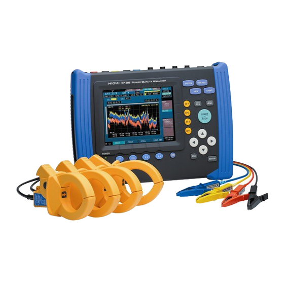
Overview 1.1 Product Overview The EN50160 version of the 3196 can measure and analyze the power supply voltage characteristics in accordance with the definitions stated in the European standard EN50160:1999 “Voltage characteristics of elec- tricity supplied by public distribution systems”. -
Page 9: Preparation For Measurement
Preparation for Measurement 2.1 EN50160 Mode and Normal Mode Model 3196 (Ver1.30 or later) can be used to measure in EN50160 mode in addition to the normal measurement of Model 3196 (nor- mal mode). When EN50160 mode is selected, the measurement function for EN50160 is added to the normal mode, and some functions in nor- mal mode will be limited. -
Page 10: En50160 Screen
2.2 EN50160 Screen In EN50160 mode, the screen for EN50160 is accessible from the "EVENT" screen. In general, there are 3 screen types, and measurement in EN50160 mode is possible only in these screens. In addition, screens for normal mode (e.g., Timeplot and DMM) can be displayed during EN50160 measurement. -
Page 11: Pc Card
2.3 PC Card When EN50160 mode is selected, the detailed data for EN50160 is saved into the PC card in real time, and only data for the display is saved in the internal memory. Using a PC card is recommended for further analysis after mea- surement by using the PC application software. -
Page 12: Limitations In En50160 Mode
2.4 Limitations in EN50160 mode The limitations are indicated below. Items Fixed value Wiring (123ch) 3P3W3M or 3P4W Frequency 50Hz PHASE-N (3P4W), U Calc Type LINE-LINE (3P3W3M) Harm Calc For EN *1 THD Calc THD_F Flicker Pst, Plt Filter 230V lamp MemoryFull LOOP Interval... -
Page 13: Default Values
2.5 Default Values When pressing the default key (F1 key) in the EN50160 setting screen [EVENT]-[DF4_Setting], the settings related to EN50160 mode is reset to the following default values that are set forth by the EN50160 standard. The settings for other parameters are not reset. - Page 14 Default value of each Harmonic order Order % of Un Order % of Un Order % of Un 25-50 Signaling S ig n a lin g p 1 S ig n a lin g p 2 (5 0 0 H z, 9 % ) (1 k H z, 5 % ) T h e firs t a re a T h e s e c o n d a re a...
-
Page 15: Measurement
Measurement 3.1 Setting Default Values To simplify the settings, Model 3196 is programmed with the set- tings as described in the EN50160 standard as default. By initializing the settings before starting measurement, EN50160 measurement can be started without making further complicated settings. -
Page 16: Starting Measurement
START key is pressed. xx:00:00, xx:10:00, xx:20:00, xx:30:00, xx:40:00, xx:50:00 Until the above times are reached, the 3196 is in waiting status. (Example) When the start key is pressed at 10:05, the 3196 waits to start measurement until 10:10. 10:10 10:05... -
Page 17: Common Display Areas
3.3.1 Common Display Areas Flagging (Including Present time or end time flagged data or Exclud- ing flagged data) Measurement start time Display methods (All/ Previous/ Specific) Start date of display An actual display period (Only when Specific Duration from start time Period of display is chosen) to end time (now) - Page 18 Sample combinations of the display method and period Method Start date Period ex.1 ex.2 Previous 1 day ex.3 Previous 1 week ex.4 Specific 01/02 (Jan./2nd) 1 day ex.5 Specific 01/02 (Jan./2nd) 1 week ex.6 Specific 01/02 (Jan./2nd) 2 weeks 1 s t 2 n d 3 rd ...
- Page 19 The ratio of Good judgment in the designated period is displayed as a numeric value and bar graph. The left end of the bar graph indicates 0% and the right end indi- cates 100%. Also, the results of the comparison ratio and the Good% is expressed by the color.
-
Page 20: Overview Screen
3.3.2 Overview Screen Display all the measurement parameters for EN50160 measure- ment. The details of each screen are explained as follows. The number of times for each event Overview Parameter name Good% Threshold level Bar graph and numeric values The following 4 parameters are simplified and displayed. Freq.A Freq.B Vvari.A... - Page 21 Changing the display method Overview (example) Select from pull- down menu Display the data from measurement start to the present (or end) time Display the data for a designated period Previous recorded prior to the present (or end) time Display the data for a designated period Specific Confirm Cancel from a specified date...
- Page 22 Changing the period of display Overview PERIOD 1 day, 1 week, 2 weeks, 3 weeks, 4 weeks Select from pull- When "Previous" or "Specific" is chosen as the dis- down menu play method, the period can be selected. Note that only periods shorter than the recorded period can be selected.
-
Page 23: Harmonic Screen
3.3.3 Harmonic Screen Display each order of Harmonic. Harmonic Changing the display method Harmonic SELECT (example) Select from pull- Display the data from measurement start down menu to the present (or end) time Display the data for a designated period Previous recorded prior to the present (or end) time... - Page 24 Changing the start date of display Harmonic SELECT From When "Specific" is chosen as the display method, the Select date date can be input. When "Previous" is chosen as the display method, "Before:Now" or "Before:End" is displayed. Confirm Cancel Changing the period of display Harmonic SELECT PERIOD...
- Page 25 Changing the flagging Harmonic Incl. Flag Excl. Flag Include flagged data in the Including flagged data statistics Do not include flagged data in Excluding flagged data the statistics This is offered to see the judgment without the effect of dip, swell and interruption events which affect all parameters.
-
Page 26: Signaling Screen
3.3.4 Signaling Screen Display the results of an analysis for all and specified frequency. Signaling The data displayed in the Signaling screen is one-day data of the specified date, because EN50160 standards require that signal- ing be assessed terms of one-day periods. However, signaling in the Overview screen is the result of statistics from the same period as other parameters. - Page 27 Changing the flagging Signaling Incl. Flag Excl. Flag Include flagged data in the Including flagged data statistics Do not include flagged data in Excluding flagged data the statistics This is offered to see the judgment without the effect of dip, swell and interruption events which affect all parameters.
-
Page 28: Events Screen
3.3.5 Events Screen Display a detailed table which indicates Dips, Swells, Interruptions and Transients. The time and level cannot be changed. Events In the normal mode, when an event occurs, an event is counted twice. e.g.) "Event IN", "Event OUT" However in the EN50160 events screen, one event is counted only once. - Page 29 Changing the display method Events (example) Select from pull- down menu Confirm Cancel Display the data from measurement start to the present (or end) time Display the data for a designated period Previous recorded prior to the present (or end) time Display the data for a designated period Specific from a specified date...
- Page 30 Changing the period of display Events PERIOD Select date Confirm Cancel 1 day, 1 week, 2 weeks, 3 weeks, 4 weeks When "Previous" or "Specific" is chosen as the dis- play method, the period can be selected. Note that only periods shorter than the recorded period can be selected.
-
Page 31: Detailed Settings
Detailed Settings 4.1 Selecting EN50160 mode Settings for EN50160 mode are made in the EN50160 setting screen. Details for each setting are as follows: Settings1 Settings for the Measurement system ..4.2 (page 29) Settings for threshold of Event......(page 32) - Page 32 Settings2 Settings for threshold of parameter ....(page 35) Settings for Good % ........(page 39) Settings3 Settings for threshold of Harmonic ....(page 40)
-
Page 33: Settings For The Measurement System
The setting contents are similar to those available in the normal 3196 mode but the settings conducted here will take priority when EN50160 mode is selected. As such, setting in the system screen of normal mode will not be possible. - Page 34 U range setting Settings1 U Range Set 123ch range only. Select from pull- 4ch range is set on the SYSTEM screen. down menu Confirm Cancel PT(VT) ratio settings Settings1 PT Ratio VARIABLE,1, 60, 100, 200, 300, 600, 700, 1000, 2000, Select from pull- 2500, 5000 down menu...
- Page 35 Nominal voltage settings Settings1 UReference Select from pull- 100V, 101V, 110V, 120V, 200V, 202V, 208V, 220V, down menu 230V, 240V, 277V, 346V, 380V, 400V, 415V, 480V, 600V, VARIABLE Nominal voltage is effective for channels 1 to 3. Confirm Cancel You can set the optional nominal voltage within the 50 to 600 range.
- Page 36 Settings for threshold of Event ___________________________________ Transient Settings1 U Transient Set transient value. Nominal voltage (UReference) is standard (100%). Setting value Over voltage(swell) Settings1 Urms SWELL Set swell value. Nominal voltage (UReference) is standard (100%). Setting value...
- Page 37 Settings1 Urms DIP Set dip value. Setting value Nominal voltage (UReference) is standard (100%). Interruption Settings1 U Interrupt Set interruption value. Nominal voltage (UReference) is standard (100%). Setting value...
- Page 38 Short interruption time Settings1 Short int T The time for a short interruption is specified. Setting value An interruption up to this period is identified as a "short interruption." An interruption longer than this period will be identi- fied as a "long interruption."...
-
Page 39: Threshold Setting
4.3 Threshold Setting The threshold values set here are compared to the measured power supply voltage characteristics for the High/Low judgment. The default values are set forth by the EN50160 standard, but they can be modified arbitrarily. Once set, these values cannot be changed during or after measurement because the calculated data during measurement will not be stored and therefore cannot be re- analyzed. - Page 40 Voltage variation A,B Settings2 V Vari.A(±) V Vari.B+ V Vari.B− The decision range is narrow. Setting value V Vari.A(±) (Plus and minus values are the same) The decision range is wide. V Vari.B +/− (Plus and minus values are different) Flicker Settings2 Flicker...
- Page 41 Unbalance Settings2 Unbalance Set unbalance value. Setting value Settings2 Set THD value. Setting value...
- Page 42 Signaling Settings2 Signaling p1 Signaling p2 Signaling p1 Threshold level and the End of fre- quency in the First area Setting value Signaling p2 Threshold level and the Start of fre- quency in the Third area S ig n a lin g p 1 S ig n a lin g p 2 (5 0 0 H z, 9 % ) (1 k H z, 5 % )
- Page 43 "Good percentage" Setting ______________________________________ Good% Settings2 Setting value Set the threshold for the ratio of “Good” judgments for the measurement period or the specified display period. This setting does not affect the measurement calcu- lations directly. The ratio is indicated in the statistics display against a blue background if the “Good”...
- Page 44 Special Settings _______________________________________________ Signaling specified frequency Settings2 Signal spec1 Signal spec2 To monitor a specific frequency, two optional fre- Setting value quencies can be specified. The frequency range is from 110 Hz to 3000 Hz in 5 Hz steps. Settings for threshold of Harmonic _______________________________ Harmonic (from 2nd to 50th) Settings3 Select item...
-
Page 45: Settings In 3196 Mode Screen
4.4 Settings in 3196 Mode Screen Normal measurement and various settings in normal mode are possible in addition to EN50160 measurement except for the limi- tations explained earlier. Set the values in normal mode as required. -
Page 46: Pc Card
PC application software. However, these data cannot be loaded to the 3196 unit. Display data “EN_DISP.EN” is data used for displaying information on the EN50160 screen of the 3196. This data can be loaded on the 3196 main unit only. -
Page 47: Specifications
Specifications The specifications not indicated in this document are stated in the standard specifications for Model 3196. 5.1 Basic Specifications Applicable version Ver1.30 or later Mode EN50160 mode (EN50160 ON), Normal mode (EN50160 OFF) The mode is selectable under the EN50160 item in the “SYSTEM-MAIN-MEASURE”... -
Page 48: In En50160 Mode, Items That Differ From Normal 3196 Specifications
5.2 In EN50160 mode, items that differ from normal 3196 specifications 1. Setting function specifications When EN50160 mode is selected, some functions in normal mode will be limited. The limitations are described in below. System settings Measured Line 3P3W3M/3P4W Measured line... - Page 49 Event settings The following items are fixed values and cannot be changed. Transient overvoltage CH1,2,3: ON, CH4:OFF Voltage swell CH1,2,3: ON Voltage dip CH1,2,3: ON Voltage interruption CH1,2,3: ON Voltage frequency ON common with Freq.A Voltage unbalance ON (fixation) factor Harmonic voltage CH1,2,3: ON, CH4: OFF Total voltage harmonic...
-
Page 50: En50160 Measurement Parameters
5.3 EN50160 Measurement Parameters Parameter name use in EN50160 Parameter name used Equivalent name on standards in Model 3196 normal 3196 EN50160 screen mode Power frequency Voltage frequency Freq.A, Freq.B Supply voltage variations RMS voltage value Vvari.A, Vvari.B Flicker severity... -
Page 51: En50160 Display Specifications
5.4 EN50160 Display Specifications EN50160 Overview display Contents of display All measurement results of EN50160 measurement parameters are displayed in the bar graph as well as under the number of event occurrences. Bar graph display The ratio of Good results in the display period is displayed as a value and a bar graph. - Page 52 EN50160 Harmonic display Display selection • Display Methods: All/ Previous/ Specific Display the data from measurement start to the present (or end) time. Previous Display the data for a designated period recorded prior to the present (or end) time. Specific Display the data for a designated period from a specified date.
- Page 53 EN50160 Events display Sorting Depth: 0 to 1% , 1 to 40%, 40 to 70%, 70 to 90% to 120%, 120 to 140%, 140 to 180% 180% or more Period: 20ms to 100ms, 100ms to 500ms, 500ms to 1s, 1s to 3s, 3s to 180s , 180s or more *1: Setting value of Interruption(default 1%)
-
Page 54: En50160 Setting Specifications
5.5 EN50160 Setting Specifications Settings1 Measurement system settings and parameter settings Setting items Setting range Default Measured line 3P3W3M, 3P4W 3P4W Voltage range 150V/300V/600V 300V VT(PT) ratio 1/60/100/200/300/600/700/1000/2000/2500/5000/ variable(0.01 to 9999.99) Nominal voltage 100/101/110/120/200/202/208/220/230/240/277/ 230V 346/380/400/415/480/600/ variable (50 to 600V in 1V steps) 40.0 to 800.0% ( 50V ≤... - Page 55 Threshold Good% Setting items Setting range Default Setting range Default Signaling p1 110Hz to (p2 freq-5Hz) 500Hz 80.0 to 100.0% 99.0% (frequency) Signaling p1 0.0 to 100.0% 9.0% (level) Signaling p2 (p1 freq+5Hz) to 1000Hz (frequency) 3000Hz Signaling p2 0.0 to 100.0% 5.0% (level) Signaling...
-
Page 56: Data Storage
× EN_DISP.EN Display data for EN50160 *1: Future release By specifying a directory to load the data, the 3196 will load the display data for EN50160 along with the time plot data and event data, which are normal measurement data. -
Page 57: En50160 Measurement Specifications
5.7 EN50160 Measurement Specifications The results of calculations are compared to the threshold at every interval. When a result is less than the threshold, it is recorded as a “Good” judgment. (Refer to the appendix for details regarding the ”ten-minute mean rms value”... - Page 58 Flicker severity (Long interval IEC voltage flicker) Calculation Plt (Plt is calculated from Pst available every 10 minutes) Plt is calculated using the following formula if “Flagging” occurs. ∑ Plt(flg) = [N = 12 - (number of Psti not flagged)] However, Plt(flg)=0 (if all Psti are flagged) Threshold default value 1.0 Good% default value...
- Page 59 Mains signaling voltage on the supply voltage Interval 3 seconds The basic measurement 10 cycles (about 200ms) time interval Calculation method Three-second mean value Frequency range 110Hz to 3,000Hz in 5Hz steps Threshold default value Refer to the following figure (Given as a percentage of the nominal voltage (Un)) Good% default value 99.0%...
- Page 60 Supply voltage dips (Voltage dip) Detection method A d ip b e g i n s w h e n t h e U voltage of one or rms(1/2) more channels is below the dip threshold and ends when the U voltage on all measured channels is equal to rms(1/2) or above the dip threshold plus the hysteresis voltage.
- Page 61 Short interruptions of the supply voltage (Voltage interruption) Long interruptions of the supply voltage (Voltage interruption) Detection method A voltage interruption begins when the U voltage of rms(1/2) one or more channels is below the voltage interruption threshold and ends when the U voltage on all mea- rms(1/2) sured channels is equal to or greater than the voltage...
-
Page 62: Calculation Formulas
5.8 Calculation Formulas Ten-minute mean rms value ∑ Ten-minutes mean rms value = r200 Number of the basic measurement time intervals during 10min of absolute time. : Calculated value in a basic measurement time interval of r200 10 cycles (200ms) The basic measurement time interval of all parameters using the ten minutes mean rms value calculation formula is 10 cycles ≅... - Page 63 HIOKI 3196 POWER QUALITY ANALYZER EN50160 MODE Instruction Manual Publication date: December 2006 Revised edition 1 Edited and published by HIOKI E.E. CORPORATION Technical Support Section All inquiries to International Sales and Marketing Department 81 Koizumi, Ueda, Nagano, 386-1192, Japan TEL: +81-268-28-0562 / FAX: +81-268-28-0568 E-mail: os-com@hioki.co.jp...
- Page 64 HEAD OFFICE 81 Koizumi, Ueda, Nagano 386-1192, Japan TEL +81-268-28-0562 / FAX +81-268-28-0568 E-mail: os-com@hioki.co.jp / URL http://www.hioki.co.jp/ HIOKI USA CORPORATION 6 Corporate Drive, Cranbury, NJ 08512, USA TEL +1-609-409-9109 / FAX +1-609-409-9108 3196A986-01 06-12H Printed on recycled paper...
Need help?
Do you have a question about the 3196 and is the answer not in the manual?
Questions and answers