Table of Contents
Advertisement
Quick Links
Advertisement
Table of Contents

Related Manuals for Hioki 3155-01


Summary of Contents for Hioki 3155-01
- Page 1 INSTRUCTION MANUAL 3155-01 LEAK CURRENT HiTESTER...
-
Page 3: Table Of Contents
Contents Introduction Inspection Safety Notes Notes on Use Contents of this Manual viii Chapter 1 Overview 1.1 Product Introduction 1.2 Features of the 3155 1.3 Measuring Mode of the 3155 1.4 Leakage Measurement Types 1.5 Standards Regarding Leakage Current Chapter 2 Names and Functions of Parts Chapter 3 Options 3.1 Measurement Networks 3.1.1 9497 NETWORK B (for the Medical Electrical Equipment) 13... - Page 4 Chapter 5 Medical Electrical Equipment Measurement Network B Installed 5.1 Leakage Current Measurement Types and Their Allowable Values for Medical Electrical Equipment 5.2 Screens (ME Equipment) 5.2.1 Initial Screen (ME Equipment) 5.2.2 Equipment Set-up Screen (ME Equipment) 5.2.3 Measuring Mode Screen (ME Equipment) 5.2.4 System Screen (ME Equipment) 5.2.5 Flow of Screens for Basic Operations (for ME Equipment) 40 5.3 Earth Leakage Current Measurement Mode (ME Equipment)
- Page 5 5.6 Patient Leakage Current Measurement Mode 5.6.1 Patient Leakage Current Measurement Mode 5.6.2 Connecting Equipment for Patient Leakage Current Measurement 5.6.3 Basic Settings for Patient Leakage Current Measurement 5.6.4 Patient Leakage Current Measurement Screen 5.7 Patient Leakage Current Measurement Mode 5.7.1 Patient Leakage Current Measurement Mode 5.7.2 Connecting Equipment for Patient Leakage Current...
- Page 6 5.11 System Screen (ME Equipment) 5.11.1 System Screen 5.11.2 Saved Data Reference Screen (ME Equipment) 5.11.3 Initialization Screen 5.11.4 Allowable Value Judgment Set-up Screen 5.11.5 Beep Sound Set-up Screen 5.11.6 Communications Set-up Screen 5.11.7 Printer Set-up Screen 5.11.8 Time and Date Set-up Screen 5.11.9 Self-test Screen 5.11.10 Language Set-up Screen Chapter 6 Ordinary Electrical Equipment Measurement...
- Page 7 6.4 Earth Leakage Current Measurement Mode (for IEC/TR 60990) 6.4.1 Earth Leakage Current Measurement Mode 6.4.2 Connecting Equipment for Earth Leakage Current Measurement (for IEC/TR 60990) 6.4.3 Zero Adjustment (Earth Leakage Current) 6.4.4 Basic Settings for Earth Leakage Current Measurement (for IEC/TR 60990) 6.4.5 Earth Leakage Current Measurement Screen (for IEC/TR 60990)
- Page 8 Chapter 7 Ordinary Electrical Equipment Measurement Network D Installed 7.1 Measurement Network D 7.2 Screens (Universal) 7.2.1 Initial Screen (Universal) 7.2.2 "Equipment Set-up" Screen (Universal) 7.2.3 Measuring Mode Screen (Universal) 7.2.4 System Screen (Universal) 7.2.5 Flow of Screens for Basic Operations (Universal) 7.3 Enclosure Leakage Current Measurement Mode (Universal) 7.3.1 Enclosure Leakage Current Measurement Mode 7.3.2 Leakage Current Measurement with the Universal...
- Page 9 7.6.3 Automatic Measurement Setting (Universal) 7.6.4 Measurement Current Setting (Universal) 7.6.5 Printing out the Maximum Values (Universal) 7.6.6 Saving the Maximum Values (Universal) 7.6.7 Low Resistance Measurement with 3157 7.7 System Screen (Universal) 7.7.1 System Screen 7.7.2 Saved Data Reference Screen (Universal) 7.7.3 Initialization Screen 7.7.4 Allowable Value Judgment Set-up Screen 7.7.5 Beep Sound Set-up Screen...
- Page 10 8.8 Command Reference 8.8.1 Format of Command Explanations 8.9.2 Commands 8.9 Reading in All the Saved Data 8.10 Sample Programs 8.11 Troubleshooting Chapter 9 Specifications 9.1 General Specifications 9.2 Measuring Mode Specifications 9.2.1 Leakage Current Measurement 9.2.2 Low Resistance Measurement 9.2.3 Monitor Function 9.3 Accuracy Tables Chapter 10 Maintenance and Servicing...
- Page 11 Appendices Appendix 1 Error Messages Appendix 2 Leakage Current Measurement Appendix 2.1 IEC 60601-1 (1988-12) + am1 (1991-11) + am2 (1995-03) 2.1.1 Earth Leakage Current 2.1.2 Enclosure Leakage Current 2.1.3 Patient Leakage Current 2.1.4 Patient Leakage Current 2.1.5 Patient Leakage Current 2.1.6 Patient Auxiliary Current Appendix 2.2 IEC 60950 (1991-10) + am4 (1996-07) Appendix 3 Standards for Leakage Current and Current...
-
Page 13: Introduction
Shipment of the unit If reshipping the unit, preferably use the original packing. Warranty HIOKI cannot be responsible for losses caused either directly or indirectly by the use of the 3155 with other equipment, or if ownership is transferred to a third party. -
Page 14: Safety Notes
──────────────────────────────────────────────────── Safety Notes This equipment is designed according to IEC 61010-1 Safety Standards, DANGER and has been tested for safety prior to shipment. During high voltage measurement, incorrect measurement procedures could result in injury or death, as well as damage to the equipment. Please read this manual carefully and be sure that you understand its contents before using the equipment. -
Page 15: Notes On Use
WARNING supply being used matches the supply voltage indicated on the rear panel of the unit. (3155: specified at order, 3155-01: set by the voltage selector) If an attempt is made to use an improper supply voltage, there is danger of damage to this unit and of life-threatening risk to the operator. - Page 16 Exercise great care when measuring voltages. In the event that the equipment malfunctions in any manner during use, turn off the power immediately, and contact your dealer or HIOKI representative. ────────────────────────────────────────────────────...
- Page 17 (120 V: 250 V T0.5 AL, 200/240 V: 250 V T0.25 AL 20 mm × 5 mm dia. (3155)) (110 to 120/200/240 V: 250 V T0.2 AL 20 mm × 5 mm dia. (3155-01)) When replacing the fuse and measurement network, always power off the unit.
- Page 18 ──────────────────────────────────────────────────── Operating environment To prevent electric shock, do not allow the unit to become wet and do WARNING not use the unit when your hands are wet. The interior of the 3155 contains some components which are subject to high voltage, and therefore dangerous. Absolutely do not remove the cover panel.
- Page 19 Using recording paper of a different specification may not only result in impaired printing quality, but even prevent the printer from operating. Always use the HIOKI specified product. ・If light reaches the paper over a long period, the paper will discolor. Do not unwrap rolls of paper until you are ready to use them.
-
Page 20: Contents Of This Manual
viii ──────────────────────────────────────────────────── Contents of this Manual The operating methods of the 3155 LEAK CURRENT HiTESTER will vary depending upon the type of measurement network used. The various operating methods for each type of measurement network are shown in Chapters 5 to 7. Although there is some repetition between chapters, to ensure safe operation please read thoroughly the chapter pertaining to the measurement network you use. -
Page 21: Chapter 1 Overview
Chapter 1 Overview 1.1 Product Introduction The HIOKI 3155 LEAK CURRENT HiTESTER is a leakage current measuring instrument for use in testing electrical equipment used in a wide variety of applications from computers to medical care. Not only does it conform to all standards for testing medical electrical equipment, but also to laws and standards applicable to equipment for non-medical care as well. -
Page 22: Features Of The 3155
──────────────────────────────────────────────────── Used by: Manufacturers of medical electrical equipment For formal inspections and pre-shipping inspections Sales agents of medical electrical equipment For inspection and maintenance Personnel performing repairs on medical electrical For inspection and maintenance equipment Clinical engineering technologists at hospital For inspection and maintenance Clinical engineering technologists training schools For educational purposes... - Page 23 The built-in thermal serial printer allows for easy printout of saved data. (8) Monitor function Equipped with a line voltage and current consumption monitor. (9) Voltage selector (3155-01 only) The equipment with the power voltages of 110 to 240 V can be measured with a single unit.
-
Page 24: Measuring Mode Of The 3155
──────────────────────────────────────────────────── 1.3 Measuring Mode of the 3155 The 3155 has been designed with the idea in mind that leakage current testing is the most important of all tests for electrical safety. In particular, for medical electrical equipment, leakage current has the greatest potential for harming human beings, and is therefore strictly regulated even with regard to single fault conditions. -
Page 25: Leakage Measurement Types
──────────────────────────────────────────────────── 1.4 Leakage Measurement Types Earth leakage current Normal condition (ordinary electrical equipment or medical electrical equipment) Interruption of one Single fault condition supply conductor A current between the protective earth terminal and the earth is measured. Enclosure leakage current Normal condition (ordinary electrical equipment or medical electrical equipment) -
Page 26: Standards Regarding Leakage Current
──────────────────────────────────────────────────── 1.5 Standards Regarding Leakage Current The measurement network you use will vary depending upon the standards to which you must conform. There are instances where testing for leakage current is required by standard to be included in formal testing, or in ownership transfer testing as well. Medical electrical equipment IEC 60601-1 (1988-12) + am1 (1991-11) + am2 (1995-03) -
Page 27: Chapter 2 Names And Functions Of Parts
──────────────────────────────────────────────────── Chapter 2 Names and Functions of Parts ────────────────────────────────────────────────────... - Page 28 ──────────────────────────────────────────────────── Liquid crystal display Top view This 5-inch display includes a touch panel which performs the role of the input keys. Monitor lamps The condition of elements such as the power line ground are indicated by these monitor lamps. When the power to the 3155 is turned on, if the MON2 and MON3 lamps are illuminated, an accurate measurement can be obtained.
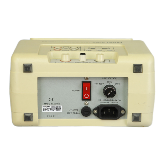
- Page 29 This is used for transporting the 3155. Main power switch Rear view Powers the 3155 on(|)or off(○) . (With the 3155-01, includes the function of the 3155 auxiliary power outlet circuit breaker.) Fuse holder Insert the proper fuse here, as indicated on the label.
- Page 30 ──────────────────────────────────────────────────── Auxiliary power outlet circuit breaker The unit uses the medium-speed breaker for the rush current of the equipment to be measured. Refer to the following table for breaking characteristics. Measurement network socket Bottom view Use this socket to attach the measurement network that conforms to your needs.
- Page 31 ──────────────────────────────────────────────────── Interior of the built-in printer Printer cover Recording paper holder Paper feed Feed switch Inside the changeover box A changeover box is built into the 3155. It is built between the power inlet and the auxiliary power socket. It outputs changing the power source polarity and the condition. So the power source polarity (normal or reverse polarity) can be changed easily, and the single fault condition (interruption of one supply conductor or interruption of a protective earth conductor) can be set easily.
- Page 32 ──────────────────────────────────────────────────── Connections of G, T1 and T2 (1) In the earth leakage current measurement mode G and the earth electrode of the auxiliary power outlet are connected to one side of the measurement network. The other side of the measurement network is connected through the protective earth terminal and its conductor to the ground.
-
Page 33: Chapter 3 Options
──────────────────────────────────────────────────── Chapter 3 Options 3.1 Measurement Networks Please choose one of the three measurement networks that simulate the human body to perform measurements conforming to standards for electrical equipment to be tested. The measurement networks cannot be used separately, but must always be installed on the 3155. -
Page 34: 9498 Network C (For Iec/Tr 60990)
──────────────────────────────────────────────────── Specifications Standard Medical electrical equipment Part 1: General requirements ofsafety (IEC 60601-1 (1988-12) + am1 (1991-11) + am2 (1995-03)) Basic measuring element 1 kΩ, frequency characteristics ±0.5% (DC to 1 MHz) Measuring circuit configuration Low pass filter function (1MΩ load with input protection fuse shorted) Filter configuration (ON setting): RC filter (10 kΩ+15 nF) Cutoff frequency, fc (at -3 dB): 1061 Hz±16 Hz Passband attenuation: 0 dB±2% (at 100 Hz) - Page 35 ──────────────────────────────────────────────────── Installation of measurement network C will enable leakage current testing that conforms to the following standards: ・Safety requirements for electrical equipment for measurement, control, and laboratory use Part 1: General requirements (IEC 61010-1 (1990-09) + am1 (1992-09) + am2 (1995-07)) ・Safety of information technology equipment (IEC 60950 (1991-10) + am4 (1996-07)) ・Audio, video and similar electronic apparatus - Safety requirements (IEC...
-
Page 36: 9499 Network D (Universal)
──────────────────────────────────────────────────── 3.1.3 9499 NETWORK D (Universal) This is a universal measurement network. Measurement network D conforms to the following standards: Safety of household and similar electrical appliances - Part 1: General requirements (IEC 60335-1 (1991-06) + am1 (1994-11)) Applicable UL standards: By installing on the 3155 and making the appropriate settings from the screen, a configuration with a network of 1 kΩ... - Page 37 ──────────────────────────────────────────────────── Typical frequency response graphs of measurement networks 9497 NETWORK B 9498 NETWORK C 9499 NETWORK D Impedance vs input frequency (1.5 kΩ//0.15 μF) ──────────────────────────────────────────────────── 3.1 Measurement Networks...
-
Page 38: 9196 Apply Unit
──────────────────────────────────────────────────── 3.2 9196 APPLY UNIT 3.2.1 9196 APPLY UNIT The 9196 APPLY UNIT is an instrument which outputs 110% of the input power voltage. Also, it has a function to break the circuit to prevent damage to the equipment to be measured and electric shock to the user if an output current exceeding 6 mA. -
Page 39: Names And Functions Of The Parts Of The 9196 Apply Unit
──────────────────────────────────────────────────── 3.2.2 Names and Functions of the Parts of the 9196 APPLY UNIT Front view Main power switch (POWER) Powers the 9196 on and off. Main power switch indication: |: ON ○: OFF Main power monitor (POWER MONI): Clear monitor lamp The status of the main power is shown by this monitor lamp. - Page 40 Handle Rear view Fuse Use the HIOKI specified fuse. (250 V T0.25 AL 20 mm×5 mm dia.) Power inlet The rated power voltage of the 9196 is 100 to 240 VAC (45 to 400 Hz), and the maximum rated power is 25 VA.
-
Page 41: 9196 Apply Unit Operation
──────────────────────────────────────────────────── 3.2.3 9196 APPLY UNIT Operation Before turning on the power, make sure that the voltage of the power WARNING supply being used matches the supply voltage indicated on the rear panel of the unit. (100 to 240 VAC) The unit has no protective ground terminal, and is connected to a ground line via a three-core power cord that is supplied with the unit. - Page 42 ──────────────────────────────────────────────────── (3) Insert the plug into the outlet. The cord is automatically grounded. (4) Attach the 9190 VOLTAGE APPLY PROBE. Attach the 9190 VOLTAGE APPLY PROBE provided to the connecting terminal on the front of the 9196. (5) Turning the power on and off. 1.
-
Page 43: 9196 Apply Unit Specifications
──────────────────────────────────────────────────── 3.2.4 9196 APPLY UNIT Specifications General specifications Output function Alternating current (AC V) Output indication Red monitor lamp Power indication Clear monitor lamp Type toggle Toggle switch (B/BF, CF) Polarity toggle Toggle switch (NORMAL /REVERSE) Output configuration Voltage application probe (9190) connector receptacle Additional functions Output control function (power cutoff) Output only when the voltage application button to the 9190 is being pressed. -
Page 44: 9388 Carrying Case (With Casters)
──────────────────────────────────────────────────── 3.3 9388 CARRYING CASE (with Casters) The 9388 CARRYING CASE (with casters) is made for storage and transport of the 3155. In addition to the 3155, it accommodates accessories, including the optional 9196 APPLY UNIT Storage of the 3155 In the carrying case, the 3155 is immobilized with Velcro tape. -
Page 45: Chapter 4 Preparations For Measurement
──────────────────────────────────────────────────── Chapter 4 Preparations for Measurement ────────────────────────────────────────────────────... -
Page 46: Installing The Measurement Network
──────────────────────────────────────────────────── 4.1 Installing the Measurement Network (1) Be sure that both the 3155 and the equipment to be measured are powered off. Be sure that the power cord, probe, leads etc. are not connected to the 3155. (2) Attach one of the three optional measurement networks (9497, 9498 and 9499). -
Page 47: Power Cord Connection
Versions of the 3155 that operate on 120 V, 200 V and 240 V of the WARNING supply voltage are available. The 3155-01 operates on 110 to 120 V, 200 V and 240 V with the voltage selector. Before turning on the power, make sure that the voltage of the power supply being used matches the supply voltage indicated on the rear panel of the unit. -
Page 48: Powering On And Off The Unit
(3155: Specify when ordering, 3155-01: Set with the voltage selector) If an attempt is made to use an improper supply voltage, there is danger of damage to this unit and of life-threatening risk to the operator. - Page 49 ──────────────────────────────────────────────────── (2) Turn the contrast adjustment knob until the screen is easy to read. Contrast adjustment knob Monitor lamps (3) After turning on the power, be sure to check the grounding condition of the power line using the monitor lamp. Proper grounding is required in order to use the functions of the 3155.
-
Page 50: Loading Recording Paper
──────────────────────────────────────────────────── 4.4 Loading Recording Paper Paper is placed in the built-in printer on the left side of the 3155. (1) Power on the 3155. Printer head (2) Open the printer cover. (3) Check that the printer head is in the home position (at Paper feed the right end in the figure). -
Page 51: Network B Installed
──────────────────────────────────────────────────── Chapter 5 Medical Electrical Equipment Measurement Network B Installed 5.1 Leakage Current Measurement Types and Their Allowable Values for Medical Electrical Equipment The following six types of leakage currents in medical electrical equipment can be tested. Earth leakage current (Class equipment only) Enclosure leakage current Patient leakage current... - Page 52 ──────────────────────────────────────────────────── Leakage current measurement types and their allowable values for medical electrical equipment (taken from IEC 60601-1 (1988-12) + am1 (1991-11) + am2 (1995-03)) Type B applied part Type BF applied part Type CF applied part Class equipment Normal Single fault condition Normal Single fault condition Normal Single fault condition condi-...
- Page 53 ──────────────────────────────────────────────────── Type B applied part Type BF applied part Type CF applied part Internally powered Normal Single fault condition Normal Single fault condition Normal Single fault condition equipment condi- condi- condi- Open Open 110% Open Open 110% Open Open 110% tion tion tion...
-
Page 54: Screens (Me Equipment)
Recommended power supply: HIOKI 7032 UNIVERSAL HiPOWER Output rating: 2 kVA (20 A/100 V range, 10 A/200 V range) -
Page 55: Initial Screen (Me Equipment)
──────────────────────────────────────────────────── 5.2.1 Initial Screen (ME Equipment) When the power is first turned on, the basic screen for controlling the 3155 immediately appears, called the initial screen. Equipment set-up: The grounding class and applied part type of the equipment to be measured Measuring mode: Earth leakage current, enclosure leakage current, patient leakage current... - Page 56 ──────────────────────────────────────────────────── Registering the model name and number. It is possible to register the model name and number before printing out or saving data. Once registered, these items will be included with the maximum values for each printout or save, unless changed. : Change to the model name input screen.
-
Page 57: Measuring Mode Screen (Me Equipment)
──────────────────────────────────────────────────── 5.2.3 Measuring Mode Screen (ME Equipment) On the measuring mode screen, press the any one of the following keys to open a window where the settings in question for that measuring mode can be changed. The following explanation uses the enclosure leakage current measurement screen as an example: : Clear the maximum value. -
Page 58: System Screen (Me Equipment)
──────────────────────────────────────────────────── 5.2.4 System Screen (ME Equipment) On the system screen, references to saved data as well as settings for beep sound, time and date, communications, and execution of self-testing can be made. : Move to the saved data reference screen. : Move to the initilization screen. - Page 59 ──────────────────────────────────────────────────── (4) Beep sound set-up screen Turn the beeper on or off. Press either the key or key. If the beep sound has been set to ON, it will be emitted under the following conditions, and the beep sound setting for the allowable value judgment become effective as well.
-
Page 60: Flow Of Screens For Basic Operations (For Me Equipment)
──────────────────────────────────────────────────── 5.2.5 Flow of Screens for Basic Operations (for ME Equipment) ・Change of screens during basic operation is as follows. ・On the measuring mode screen, measured values can be checked in real time. Example: When performing enclosure leakage current measurement Initial screen Equipment set-up screen Set the grounding class and applied... -
Page 61: Earth Leakage Current Measurement Mode (Me Equipment)
──────────────────────────────────────────────────── 5.3 Earth Leakage Current Measurement Mode (ME Equipment) 5.3.1 Earth Leakage Current Measurement Mode Earth leakage current measurement for medical electrical equipment is performed only when class equipment has been set. When either class internally powered equipment has been set, the earth leakage current key on the initial screen is non-selectable. -
Page 62: Connecting Equipment For Earth Leakage Current
(With the 3155-01, the main power switch is turned off.) ・When power of the equipment to be measured exceeds 1500VA, make the connection directly to the outlet;... - Page 63 ──────────────────────────────────────────────────── ・When the auxiliary power socket does not fit the power plug of the NOTE equipment to be measured, use the supplied power plug. ・Use wire for connecting the functional earth terminals of the equipment to be measured, or an F-type applied part to the ground. ・When the equipment to be measured requires the use a single phase power source, connect the 3155 between the power source and the single phase power source, as well as between the single phase power source and the...
-
Page 64: Zero Adjustment (Earth Leakage Current)
──────────────────────────────────────────────────── 5.3.3 Zero Adjustment (Earth Leakage Current) In cases where the extension cable (power socket conversion cable, table tap, etc.) is connected to the auxiliary power socket when making a measurement, the measured value may be subject to leakage current of the extension cable. In which case, to obtain an accurate measurement, perform zero adjustment before measuring. -
Page 65: Basic Settings For Earth Leakage Current Measurement
──────────────────────────────────────────────────── 5.3.4 Basic Settings for Earth Leakage Current Measurement (ME Equipment) This illustrates basic setting and reference categories until measurement. Preparations for measurement follow Section 5.3.2, "Connecting Equipment for Earth Leakage Current Measurement." Equipment set-up screen Initial screen Set the grounding class to class Set the applied part type. -
Page 66: Earth Leakage Current Measurement Screen
──────────────────────────────────────────────────── 5.3.5 Earth Leakage Current Measurement Screen (ME Equipment) Measurement of earth leakage current is made on the earth leakage current measurement screen. The current measured value, maximum value, and setting condition are shown on the earth leakage current measurement screen. Further, windows for changing the measurement settings can be opened from this screen. - Page 67 ──────────────────────────────────────────────────── (2) Settings Description of the function Use as necessary to clear unnecessary data and start new measurements. As long as this key is not pressed, the maximum value is not cleared even after (Clear the maximum changing measurement settings in the same measuring mode. value) The maximum value is cleared after changing the measuring mode.
-
Page 68: Enclosure Leakage Current Measurement Mode (Me Equipment)
──────────────────────────────────────────────────── 5.4 Enclosure Leakage Current Measurement Mode (ME Equipment) 5.4.1 Enclosure Leakage Current Measurement Mode The measurement of enclosure leakage current for medical electrical equipment is performed in two places: between the enclosure and the earth, and between parts of the enclosure. With class equipment, the enclosure is each part of the enclosure which is not protectively earthed. - Page 69 ──────────────────────────────────────────────────── ・Do not apply 110% voltage if there is any chance that circuitry or other physical components of the instrument might be damaged. ・By using the automatic measurement mode, it is possible to measure changing automatically the power source polarity and condition of the equipment to be measured, and obtain the maximum value of the combination.
-
Page 70: Connecting Equipment For Enclosure Leakage Current
(With the 3155-01, the main power switch is turned off.) ・When power of the equipment to be measured exceeds 1500VA, make the connection directly to the outlet;... - Page 71 ──────────────────────────────────────────────────── For 110% applied voltage Make the appropriate output settings for the 9196 APPLY UNIT. Set the polarity toggle switch and the type toggle switch to match the applied part type of the equipment to be measured. POLARITY: NORMAL or REVERSE APPLIED PART (TYPE): B/BF, CF Touch the voltage application probe of the 9196 APPLY UNIT to the signal input or signal output part which is not protectively earthed of the equipment...
- Page 72 ──────────────────────────────────────────────────── (2) Measurement between parts of the enclosure (With class equipment, between parts of the enclosure which is not protectively earthed) 1. On the enclosure leakage current measurement screen, set the contact condition to "between parts of the enclosure." 2. Plug the power cord of the equipment to be measured into the auxiliary power socket found on the right side of the 3155.
- Page 73 ──────────────────────────────────────────────────── ・When the auxiliary power socket does not fit the power plug of the NOTE equipment to be measured, use the supplied power plug. ・Do not apply 110% voltage if there is any chance that circuitry or other physical components of the instrument might be damaged. ・When testing class 0I or other older models, use (UL1015, AWG #18 or equivalent) wire to connect the G terminal with the protective earth terminal of the equipment to be measured.
-
Page 74: Basic Settings For Enclosure Leakage Current
──────────────────────────────────────────────────── 5.4.3 Basic Settings for Enclosure Leakage Current Measurement (ME Equipment) This illustrates basic settings and reference categories until measurement. Preparations for measurement follow Section 5.4.2, "Connecting Equipment for Enclosure Leakage Current Measurement." Equipment set-up screen Initial screen Set the grounding class and applied part type of the equipment to be measured, and register the model name and number. -
Page 75: Enclosure Leakage Current Measurement Screen
──────────────────────────────────────────────────── 5.4.4 Enclosure Leakage Current Measurement Screen (ME Equipment) Measurement of enclosure leakage current is made on the enclosure leakage current measurement screen. The current measured value, maximum value, and setting condition are shown on the enclosure leakage current measurement screen. Further, windows for changing the measurement settings can be opened from this screen. - Page 76 ──────────────────────────────────────────────────── Allowable value Current setting of the allowable value in normal condition or single fault condition Setting display for the The following parameters are displayed: equipment to be measured Settings of the equipment to be measured Model name, Number, Current consumption monitor value, Line voltage monitor value (2) Settings Description of the function...
-
Page 77: Patient Leakage Current
──────────────────────────────────────────────────── 5.5 Patient Leakage Current Measurement Mode 5.5.1 Patient Leakage Current Measurement Mode Explanations made in this Instruction Manual conform to IEC 60601-1 (1988-12) + am1 (1991-11) + am2 (1995-03) standards. Measurements made in accordance with IEC 60601-1 (1988-12) + am1 (1991-11) + am2 (1995-03) standards are made with both alternating (AC) and direct (DC) current. - Page 78 ──────────────────────────────────────────────────── Measurement types and their allowable values Type B applied part Type BF applied part Type CF applied part Class equipment Normal Single fault condition Normal Single fault condition Normal Single fault condition condi- condi- condi- Open Open Open Open Open Open tion...
-
Page 79: Connecting Equipment For Patient Leakage Current
(With the 3155-01, the main power switch is turned off.) ・When power of the equipment to be measured exceeds 1500VA, make the connection directly to the outlet;... - Page 80 ──────────────────────────────────────────────────── ・When the auxiliary power socket does not fit the power plug of the NOTE equipment to be measured, use the supplied power plug. ・When testing class 0I or other older models, use (UL1015, AWG #18 or equivalent) wire to connect the G terminal with the protective earth terminal of the equipment to be measured.
-
Page 81: Basic Settings For Patient Leakage Current
──────────────────────────────────────────────────── 5.5.3 Basic Settings for Patient Leakage Current Measurement This illustrates basic settings and reference categories until measurement. Preparations for measurement follow Section 5.5.2, "Connecting Equipment for Patient Leakage Current ." Equipment set-up screen Initial screen Set the grounding class and applied part type of the equipment to be measured, and register the model name and number. -
Page 82: Patient Leakage Current
──────────────────────────────────────────────────── 5.5.4 Patient Leakage Current Measurement Screen Measurement of patient leakage current is made on the patient leakage current measurement screen. The current measured value, maximum value, and setting condition are shown on the patient leakage current measurement screen. Further, windows for changing the measurement settings can be opened from this screen. - Page 83 ──────────────────────────────────────────────────── Power source polarity for the Connection with the power source current value Normal: , Reverse: Condition of the equipment to Condition of the equipment to be measured be measured for the current Normal condition: value Single fault condition (open power lead): Single fault condition (open ground): Allowable value Current setting of the allowable value in normal condition or single fault...
- Page 84 ──────────────────────────────────────────────────── 5.6 Patient Leakage Current Measurement Mode 5.6.1 Patient Leakage Current Measurement Mode Patient leakage current measurement for medical electrical equipment is performed only for equipment with a type B applied part. Plug the power cord of the equipment to be measured into the auxiliary socket for the 3155, and make a measurement by touching 9170 TEST LEADS to the test point (applied part), and applying voltage from the optional 9196 APPLY UNIT.
- Page 85 (With the 3155-01, the main power switch is turned off.) ・When power of the equipment to be measured exceeds 1500VA, make the connection directly to the outlet;...
- Page 86 ──────────────────────────────────────────────────── 1. Plug the power cord of the equipment to be measured into the auxiliary power socket found on the right side of the 3155. No connection is made for internally powered equipment. 2. Connect the red 9170 TEST LEAD to the leakage current measurement terminal T2.
- Page 87 ──────────────────────────────────────────────────── 5.6.3 Basic Settings for Patient Leakage Current Measurement This illustrates basic settings and reference categories until measurement. Preparations for measurement follow Section 5.6.2, "Connecting Equipment for Patient Leakage Current ." Equipment set-up screen Initial screen Set the grounding class of the equipment to be measured.
- Page 88 ──────────────────────────────────────────────────── 5.6.4 Patient Leakage Current Measurement Screen Measurement of patient leakage current is made on the patient leakage current measurement screen. The current measured value, maximum value, and setting condition are shown on the patient leakage current measurement screen. Further, windows for changing the measurement settings can be opened from this screen.
- Page 89 ──────────────────────────────────────────────────── Allowable value Current setting of the allowable value (Single fault condition only) Setting display for the The following parameters are displayed: equipment to be measured Settings of the equipment to be measured Model name, Number, Current consumption monitor value, Line voltage monitor value (2) Settings Description of the function...
- Page 90 ──────────────────────────────────────────────────── 5.7 Patient Leakage Current Measurement Mode 5.7.1 Patient Leakage Current Measurement Mode Patient leakage current measurement for medical electrical equipment is performed only for equipment with a type BF or type CF applied part. Plug the power cord of the equipment to be measured into the auxiliary socket for the 3155, and make a measurement by touching 9170 TEST LEADS to the test point (applied part), and applying voltage from the optional 9196 APPLY UNIT.
- Page 91 (With the 3155-01, the main power switch is turned off.) ・When power of the equipment to be measured exceeds 1500VA, make the connection directly to the outlet;...
- Page 92 ──────────────────────────────────────────────────── 1. Plug the power cord of the equipment to be measured into the auxiliary power socket found on the right side of the 3155. No power cord connection is made for internally powered equipment. 2. Connect the black 9170 TEST LEAD to the leakage current measurement terminal T1.
- Page 93 ──────────────────────────────────────────────────── 5.7.3 Zero Adjustment (ME Equipment - Patient Leakage Current In cases where the voltage from the 9196 APPLY UNIT or other voltage application devices is applied to the 3155 when making a measurement, the measured value may be subject to synchronous voltage. In which case, an accurate measurement cannot be obtained without first performing zero adjustment.
- Page 94 ──────────────────────────────────────────────────── 5.7.4 Basic Settings for Patient Leakage Current Measurement This illustrates basic settings and reference categories until measurement. Preparations for measurement follow Section 5.7.2, "Connecting Equipment for Patient Leakage Current ." Equipment set-up screen Initial screen Set the grounding class of the equipment to be measured.
- Page 95 ──────────────────────────────────────────────────── 5.7.5 Patient Leakage Current Measurement Screen Measurement of patient leakage current is made on the patient leakage current measurement screen. The current measured value, maximum value, and setting condition are shown on the patient leakage current measurement screen. Further, windows for changing the measurement settings can be opened from this screen.
- Page 96 ──────────────────────────────────────────────────── Condition of the equipment to Condition of the equipment to be measured be measured for the current Single fault condition (110% voltage applied): value Allowable value Current setting of the allowable value (Single fault condition only) Setting display for the The following parameters are displayed: equipment to be measured Settings of the equipment to be measured...
- Page 97 ──────────────────────────────────────────────────── 5.8 Patient Auxiliary Current Measurement Mode 5.8.1 Patient Auxiliary Current Measurement Mode Patient auxiliary current measurement for medical electrical equipment is made with both alternating (AC) and direct (DC) current. Plug the power cord of the equipment to be measured into the auxiliary socket for the 3155, and make a measurement by touching the 9170 TEST LEADS to the test point (applied part).
- Page 98 ──────────────────────────────────────────────────── Measurement types and their allowable values Type B applied part Type BF applied part Type CF applied part Class equipment Normal Single fault condition Normal Single fault condition Normal Single fault condition condi- condi- condi- Open Open Open Open Open Open tion...
- Page 99 (With the 3155-01, the main power switch is turned off.) ・When power of the equipment to be measured exceeds 1500VA, make the connection directly to the outlet;...
- Page 100 ──────────────────────────────────────────────────── Insulating transformer Red 9170 TEST LEAD Equipment to Black 9170 TEST LEAD be measured Applied parts ・When the auxiliary power socket does not fit the power plug of the NOTE equipment to be measured, use the supplied power plug. ・When testing class 0I or other older models, use (UL1015, AWG #18 or equivalent) wire to connect the G terminal with the protective earth terminal of the equipment to be measured.
- Page 101 ──────────────────────────────────────────────────── 5.8.3 Basic Settings for Patient Auxiliary Current Measurement This illustrates basic settings and reference categories until measurement. Preparations for measurement follow Section 5.8.2, "Connecting Equipment for Patient Auxiliary Current Measurement." Equipment set-up screen Initial screen Set the grounding class and applied part type of the equipment to be measured, and register the model name and number.
- Page 102 ──────────────────────────────────────────────────── 5.8.4 Patient Auxiliary Current Measurement Screen Measurement of patient auxiliary current is made on the patient auxiliary current measurement screen. The current measured value, maximum value, and setting condition are shown on the patient auxiliary current measurement screen. Further, windows for changing the measurement settings can be opened from this screen.
- Page 103 ──────────────────────────────────────────────────── Power source polarity for the Connection with the power source current value Normal: , Reverse: Condition of the equipment to Condition of the equipment to be measured be measured for the current Normal condition: value Single fault condition (open power lead): Single fault condition (open ground): Allowable value Current setting of the allowable value in normal condition or single fault...
- Page 104 ──────────────────────────────────────────────────── 5.9 Low Resistance Measurement Mode (ME Equipment) 5.9.1 Low Resistance Measurement Mode Under IEC 60601-1 (1988-12) + am1 (1991-11) + am2 (1995-03), measurement of resistance of the protective earth conductor is to be made at 25 AAC of current. The 3155, however, makes this measurement simply using the DC four-terminal method (at 100 mADC max.).
- Page 105 ──────────────────────────────────────────────────── 5.9.2 Connecting Equipment for Low Resistance Measurement (ME Equipment) Do not input a voltage exceeding 30 Vrms, 42.4 Vpeak or 50 VDC between WARNING the resistance measurement terminals, and between the resistance measurement terminal and the ground. ・Be careful not to hurt yourself on the end of the 9461 PIN-TYPE LEADS, CAUTION which is pointed.
- Page 106 ──────────────────────────────────────────────────── As shown in the figure, the 9461 PIN-TYPE NOTE LEAD has a SENSE sheathed by the SOURCE. When touched to the equipment to be measured, both the SENSE and the SOURCE SOURCE must be in contact with the equipment to be measured. SENSE When not in use During measurement...
- Page 107 ──────────────────────────────────────────────────── (3) When using 3157 AC GROUNDING HiTESTER ・Do not make measurements if the power cord of the equipment to be CAUTION measured is plugged into the auxiliary power outlet of the 3155. ・Do not touch the equipment to be measured until measurement is complete. When measuring in low resistance measurement mode using optional 3157 AC GROUNDING HiTESTER, using the RS-232C interface enable the 3155 to control the 3157.
- Page 108 ──────────────────────────────────────────────────── 5.9.3 Basic Settings for Low Resistance Measurement (ME Equipment) This illustrates basic setting and reference categories until measurement. Preparations for measurement follow Section 5.9.2, "Connecting Equipment for Low Resistance Measurement." Initial screen Low resistance measurement mode Allowable value set-up window screen Set the allowable value referring to Section 5.10.2, "Allowable Value Setting."...
- Page 109 ──────────────────────────────────────────────────── 5.9.4 Low Resistance Measurement Screen (ME Equipment) With 3155 measuring equipment settings selected on low resistance measurement screen, measurement starts immediately and displays current value. When measuring with 3157 measuring equipment settings, measurement does not start until pressing the 2...
- Page 110 ──────────────────────────────────────────────────── (2) Settings Description of the function Use as necessary to clear unnecessary data and start new measurements. As long as this key is not pressed, the maximum value is not cleared even after (Clear the maximum changing measurement settings in the same measuring mode. value) The maximum value is cleared after changing the measuring mode.
- Page 111 ──────────────────────────────────────────────────── 5.10 Condition Set-up Window Setting (ME Equipment) 5.10.1 Allowable Value Setting (For Leakage Current Measurement) The allowable value setting may be revised as necessary to accommodate the measuring mode and condition of the equipment to be measured (normal condition or single fault condition). The 3155 can set two allowable values in normal condition and single fault condition.
- Page 112 ──────────────────────────────────────────────────── (2) Press the normal or fault key to select the desired allowable value. (3) Using the numerical keys, input the desired value. (After pressing the numerals key) Press the key to clear mistakes. (4) After the numeric value is input correctly, press either unit key to finalize the input.
- Page 113 ──────────────────────────────────────────────────── 5.10.2 Allowable Value Setting (For Low Resistance Measurement) Low resistance measurement is performed only for grounding class equipment. The allowable value setting may be revised as necessary. When shipped, 100 mΩ is set. Settings (1) On the measuring mode screen, press the key to open the allowable value set-up window.
- Page 114 ──────────────────────────────────────────────────── (4) After making the setting, press the key to close the allowable value set-up window. (5) The allowable value judgment can be turned ON or OFF on the allowable value judgment set-up screen of the system screen. If set to OFF, the allowable values are not displayed on the measuring mode screen.
- Page 115 ──────────────────────────────────────────────────── 5.10.3 Automatic Measurement Setting (ME Equipment) In each of the leakage current measurement modes, automatic measurement can be performed, in which the polarity and condition of the equipment to be measured are automatically changed. The combinations shown below are all set, and the maximum value of each combination is measured.
- Page 116 ──────────────────────────────────────────────────── (5) On the measuring mode screen, press the key to start automatic measurement. When the measurement of a particular condition is finished, if it exceeds the current maximum value, the maximum value is revised to the new value. During measurements, the key is displayed.
- Page 117 ──────────────────────────────────────────────────── Automatic measurement result screen After the automatic measurements have been completed, the automatic measurement result screen is displayed. Measuring mode Model name Number Measurement network filter setting Measurement current Maximum value Power source polarity Condition of the equipment to be measured Judgment Contact condition...
- Page 118 ──────────────────────────────────────────────────── Example of the automatic measurement results printout Printout of the automatic measurements in the enclosure leakage current ──────────────────────────────────────────────────── 5.10 Condition Set-up Window Setting (ME Equipment)
- Page 119 ──────────────────────────────────────────────────── 5.10.4 Measurement Current Setting (ME Equipment) This is where the measurement current is set. Explanations made in this Instruction Manual conform to IEC 60601-1 (1988-12) + am1 (1991-11) + am2 (1995-03) standards. Settings (1) Press the key on the leakage current measurement mode screen to open the measurement current set-up window.
- Page 120 ──────────────────────────────────────────────────── 5.10.5 Printing out the Maximum Values (ME Equipment) The printer can be used to print out the maximum values and measurement settings for each measuring mode. When printing out the maximum values, the model name and number registered on the equipment set-up screen can be changed.
- Page 121 ──────────────────────────────────────────────────── 5.10.6 Saving the Maximum Values (ME Equipment) The maximum values are saved with the model name and number registered on the equipment set-up screen. The power source polarity, condition of the equipment to be measured, etc. during measurement are also saved. When saving the maximum values, the model name and number can be changed.
- Page 122 ──────────────────────────────────────────────────── ・A part of the condition of the equipment to be measured is omitted depending on the settings of the grounding class and applied part type of the equipment to be measured. ・In the following cases, model name and number must be changed for storage as a different data unit.
- Page 123 ──────────────────────────────────────────────────── 5.10.7 Low Resistance Measurement with 3157 Low resistance measurement mode allows measurement with optional 3157 AC GROUNDING HiTESTER (maximum 31 AAC, in accordance with multiple standards). Using the RS-232C interface enable the 3155 to control the 3157. Prior to set up, connect 3157 to equipment to be measured and 3157 to 3155 with connection cable.
- Page 124 ──────────────────────────────────────────────────── ・Measurement cannot be carried out for approximately five seconds after turning the 3157 power ON. ・When the 3157 optional function setting screen is set, measurement cannot be carried out. ・Do not press the key before connecting RS-232C cable and 3157. ・When 3157 maximum test value is set under 0.010 Ω, 3155 allowable value defaults to 0.010 Ω...
- Page 125 ──────────────────────────────────────────────────── 5.11 System Screen (ME Equipment) 5.11.1 System Screen On the initial screen, press the key to move to the system screen. On the system screen, processing of saved data as well as settings for sounds, time and date, and communications, and execution of self-testing can be made.
- Page 126 ──────────────────────────────────────────────────── 5.11.2 Saved Data Reference Screen (ME Equipment) The following is an explanation of how to use the saved data. Up to 100 data units can be saved. However, up to 2000 data can be saved. For the model name and number settings, refer to Section 5.2.2, "Equipment Set-up Screen (ME Equipment)."...
- Page 127 ──────────────────────────────────────────────────── (3) Keys : Used to select an entry : Used to select an entry : Delete the data unit for the current entry : Print the data unit for the current entry : Details of the saved data reference screen are displayed. : Select an entry, and display its condition at time of maximum value judgment.
- Page 128 ──────────────────────────────────────────────────── (6) Details of the saved data reference screen Use the key to select the desired measuring mode for the details to display. Press the key to display the details of the saved data for the selected measuring mode. The maximum values for each combination of the power source polarity and condition of the equipment to be measured are displayed.
- Page 129 ──────────────────────────────────────────────────── Example of a data unit printout: Example of a details printout: ──────────────────────────────────────────────────── 5.11 System Screen (ME Equipment)
- Page 130 ──────────────────────────────────────────────────── 5.11.3 Initialization Screen Initialize the 3155. : Perform a system reset. (Delete all the saved data.) : Delete all the saved data. : Return to the system screen. (1) System reset Press the key to open the window to confirm a system reset.
- Page 131 ──────────────────────────────────────────────────── 5.11.4 Allowable Value Judgment Set-up Screen Setting the allowable value judgment (comparison with the maximum value and current value) : Perform the allowable value judgment. If the maximum value and current value are less than or equal to the allowable value, PASS is displayed, if higher than the allowable value, FAIL.
- Page 132 ──────────────────────────────────────────────────── 5.11.6 Communications Set-up Screen For details, refer to Section 8.5.1, "Communication Conditions Setting." 5.11.7 Printer Set-up Screen The following is an example of how to adjust the contrast and perform a test printout. The printer contrast is easily affected by the temperature of the surrounding area.
- Page 133 ・If the RAM operates properly, the "RAM TEST OK!" message is displayed. ・If the RAM does not operate properly, the "RAM TEST NG!" message is displayed. In this case, contact your dealer or HIOKI representative. (2) KEY test Press the key to test the touch panel for proper operation.
- Page 134 ──────────────────────────────────────────────────── 5.11.10 Language Set-up Screen Set the language displayed on the screen. (1) English → Japanese : Set the display language to Japanese. (2) Japanese → English : Set the display language to English. ──────────────────────────────────────────────────── 5.11 System Screen (ME Equipment)
- Page 135 ──────────────────────────────────────────────────── Chapter 6 Ordinary Electrical Equipment Measurement Network C Installed ────────────────────────────────────────────────────...
- Page 136 ──────────────────────────────────────────────────── 6.1 Measurement Network C The 9498 NETWORK C (conforms to IEC/TR 60990) is used for the electrical measuring instrument and information technology equipment. Measurement network C conforms to the following standard. Methods of measurement of touch-current and and protective conductor current (IEC/TR 60990 (1990-06)) By changing the filter setting to a body impedance network (OFF), a perception and reaction network (ON1) or a let-go network (ON2), the...
- Page 137 ──────────────────────────────────────────────────── 6.1.1 Leakage Current Measurement Types and Their Allowable Values for Ordinary Electrical Equipment The 3155 unit contains an allowable value judgment function, which compares the maximum value to the allowable value. To use this function, set the judgment function to ON, and set each of the allowable values.
- Page 138 ──────────────────────────────────────────────────── 6.2 Screens (for IEC/TR 60990) About the Touch Panel Do not press hard upon the touch screen, or operate it using a hard object or CAUTION one with a sharp end. Doing so could scratch or damage the screen or the soft keys.
- Page 139 ──────────────────────────────────────────────────── 6.2.2 "Equipment Set-up" Screen (for IEC/TR 60990) On the initial screen, press the key to open the equipment set-up screen. On the equipment set-up screen, a setting for the grounding class of the equipment to be measured, and registration of the model name and number can be made. Press the key to return to the initial screen.
- Page 140 ──────────────────────────────────────────────────── Setting Shown on the left are examples of the model name input screens. A maximum of 12 characters can be input. Clear the model name or number Back space Toggle between alphabet input and numeric input Alphabet input screen Close the input window Numeric input screen ────────────────────────────────────────────────────...
- Page 141 ──────────────────────────────────────────────────── 6.2.3 Measuring Mode Screen (for IEC/TR 60990) On the measuring mode screen, press the any one of the following keys to open a window where the settings in question for that measuring mode can be changed. The following explanation uses the enclosure leakage current measurement screen as an example: : Clear the maximum value.
- Page 142 ──────────────────────────────────────────────────── 6.2.4 System Screen (for IEC/TR 60990) On the system screen, references to saved data as well as settings for beep sound, time and date, communications, and execution of self-testing can be made. : Move to the saved data reference screen. : Move to the initilization screen.
- Page 143 ──────────────────────────────────────────────────── (4) Beep sound set-up screen Turn the beeper on or off. Press either the key or key. If the beep sound has been set to ON, it will be emitted under the following conditions, and the beep sound setting for the allowable value judgment become effective as well.
- Page 144 ──────────────────────────────────────────────────── 6.2.5 Flow of Screens for Basic Operations (for IEC/TR 60990) ・Change of screens during basic operation is as follows. ・On the measuring mode screen, measured values can be checked in real time. Initial screen Equipment set-up screen Set the grounding class of the equipment to be measured, and register the model name and number.
- Page 145 ──────────────────────────────────────────────────── 6.3 Enclosure Leakage Current Measurement Mode (for IEC/TR 60990) The enclosure leakage current measurement is performed in two places: between the enclosure and the earth, and between the enclosure and the power line. With class equipment, the enclosure is each part of the enclosure which is not protectively earthed.
- Page 146 ──────────────────────────────────────────────────── 6.3.1 Measurement Accompanying IEC 60950 (1991-10) + am4 (1996-07) IEC/TR 60990 (1990-06) sets standard measurement methods for current. IEC 60950 (1991-10) + am4 (1996-07), IEC 61010-1 (1990-09) + am1 (1992-09) + am2 (1995-07), etc. use the methods of IEC/TR 60990 (1990-06). (1) Earth leakage current measurement When performing earth leakage current measurements with the 3155 intended to conform to IEC 60950 (1991-10) + am4 (1996-07), use the enclosure leakage...
- Page 147 ──────────────────────────────────────────────────── (2) Measurement of leakage current to a telecommunication network Use the enclosure leakage current mode. Connect the power plug of the equipment to be measured to the power outlet, using the insulating transformer and the table tap, and touch the test point with the 9170 TEST LEAD.
- Page 148 (With the 3155-01, the main power switch is turned off.) ・If enclosure leakage current is to be measured between the enclosure and the power supply line, or the power of the equipment to be measured exceeds 1500VA, make the connection directly to the outlet;...
- Page 149 ──────────────────────────────────────────────────── 4. Connect the red 9170 TEST LEAD to the leakage current measurement terminal T2, and the black one to T1. 5. Plug the red 9170 TEST LEAD into the table tap. 6. Perform zero adjustment. For details, refer to "Zero Adjustment (for IEC/TR 60990 - Earth Leakage Current).
- Page 150 ──────────────────────────────────────────────────── (2) Measurement of leakage current to a telecommunication network 1. On the enclosure leakage current measurement screen, set the contact condition to "between the enclosure and the earth." 2. Plug the power cord of the equipment to be measured into a table tap. 3.
- Page 151 ──────────────────────────────────────────────────── 6.3.3 Zero Adjustment (for IEC/TR 60990 - Enclosure Leakage Current) In cases where the direct power line is connected to the 3155 leakage current measurement terminal when making a measurement, the measured value may be subject to synchronous voltage. In which case, an accurate measurement cannot be obtained without first performing zero adjustment.
- Page 152 ──────────────────────────────────────────────────── 6.3.4 Measurement Accompanying IEC 61010-1 (1990-09) + am1 (1992-09) + am2 (1995-07) IEC/TR 60990 (1990-06) sets standard measurement methods for current. IEC 60950 (1991-10) + am4 (1996-07), IEC 61010-1 (1990-09) + am1 (1992-09) + am2 (1995-07), etc. use the methods of IEC/TR 60990 (1990-06). When performing current measurements with the 3155 intended to conform to IEC 61010-1 (1990-09) + am1 (1992-09) + am2 (1995-07), use the enclosure leakage current measurement mode.
- Page 153 (With the 3155-01, the main power switch is turned off.) ・When power of the equipment to be measured exceeds 1500VA, make the connection directly to the outlet;...
- Page 154 ──────────────────────────────────────────────────── Red 9170 TEST LEAD 9195 Equipment to be measured When the auxiliary power socket does not fit the power plug of the equipment NOTE to be measured, use the supplied power plug. If the enclosure or any part thereof is made of material with insulating characteristics If the enclosure or any part thereof is made of material with insulating characteristics, attach the 9195 ENCLOSURE PROBE to the enclosure at...
- Page 155 ──────────────────────────────────────────────────── 6.3.6 Basic Settings for Enclosure Leakage Current Measurement (for IEC/TR 60990) This illustrates basic settings and reference categories until measurement. Preparations for measurement follow Section 6.3.2, "Connecting Equipment for Enclosure Leakage Current Measurement", and 6.3.5, "Connecting Equipment for Measurement Accompanying IEC 1010-1 ’90 Amendment 2 ’95." Initial screen Equipment set-up screen Set the grounding class of the equipment...
- Page 156 ──────────────────────────────────────────────────── 6.3.7 Enclosure Leakage Current Measurement Screen (for IEC/TR 60990) Measurements of enclosure leakage current are made on the enclosure leakage current measurement screen. The current measured value, maximum value, and set-up status are shown on the enclosure leakage current measurement screen. Further, windows for changing the designations for each measurement can be opened from this screen.
- Page 157 ──────────────────────────────────────────────────── Current value judgment Result of comparison of the current value with the allowable value (In cases where the measurement current is DC, an absolute value.) PASS : Allowable value or lower F A I L : Higher than the allowable value Power source polarity for the Connection with the power source current value...
- Page 158 ──────────────────────────────────────────────────── Opens the measurement current set-up window. Set the measurement current. When set to AC peak, the filter cannot be set to OFF. If set to OFF, it automatically changes to ON1. When set to DC, the filter cannot be set to ON2. If set to ON2, it automatically changes to OFF.
- Page 159 ──────────────────────────────────────────────────── 6.4 Earth Leakage Current Measurement Mode (for IEC/TR 60990) 6.4.1 Earth Leakage Current Measurement Mode Earth leakage current measurement is performed only when class equipment has been set. When either class or internally powered equipment has been set, the earth leakage current key on the initial screen is non-selectable.
- Page 160 (With the 3155-01, the main power switch is turned off.) ・When power of the equipment to be measured exceeds 1500VA, make the connection directly to the outlet;...
- Page 161 ──────────────────────────────────────────────────── 6.4.3 Zero Adjustment (Earth Leakage Current) In cases where the extension cable (power socket conversion cable, table tap, etc.) is connected to the auxiliary power socket when making a measurement, the measured value may be subject to leakage current of the extension cable. In which case, to obtain an accurate measurement, perform zero adjustment before measuring.
- Page 162 ──────────────────────────────────────────────────── 6.4.4 Basic Settings for Earth Leakage Current Measurement (for IEC/TR 60990) This illustrates basic setting and reference categories until measurement. Preparations for measurement follow Section 6.4.2, "Connecting Equipment for Earth Leakage Current Measurement." Initial screen Equipment set-up screen Set the grounding class of the equipment to be measured to class Polarity and equipment condition...
- Page 163 ──────────────────────────────────────────────────── 6.4.5 Earth Leakage Current Measurement Screen (for IEC/TR 60990) Measurement of earth leakage current is made on the earth leakage current measurement screen. The current measured value, maximum value, and setting condition are shown on the earth leakage current measurement screen. Further, windows for changing the measurement settings can be opened from this screen.
- Page 164 ──────────────────────────────────────────────────── Current value judgment Result of comparison of the current value with the allowable value (In cases where the measurement current is DC, an absolute value.) PASS : Allowable value or lower F A I L : Higher than the allowable value Power source polarity for the Connection with the power source current value...
- Page 165 ──────────────────────────────────────────────────── Opens the measurement current set-up window. Set the measurement current. When set to AC peak, the filter cannot be set to OFF. If set to OFF, it automatically changes to ON1. When set to DC, the filter cannot be set to ON2. If set to ON2, it automatically changes to OFF.
- Page 166 ──────────────────────────────────────────────────── 6.5 Low Resistance Measurement Mode (for IEC/TR 60990) 6.5.1 Low Resistance Measurement Mode Under IEC 60950 (1991-10) + am4 (1996-07), measurement of resistance between the protective earth terminal or earth contact and the part required to be earthed is to be made at not more than 25 AAC or DC of current. (The resistance is calculated from the voltage drop.) The 3155, however, makes this measurement simply using the DC four-terminal method (at 100 mADC max.).
- Page 167 ──────────────────────────────────────────────────── 6.5.2 Connecting Equipment for Low Resistance Measurement (for IEC/TR 60990) Do not input a voltage exceeding 30 Vrms, 42.4 Vpeak or 50 VDC between WARNING the resistance measurement terminals, and between the resistance measurement terminal and the ground. ・Be careful not to hurt yourself on the end of the 9461 PIN-TYPE LEAD, CAUTION which is pointed.
- Page 168 ──────────────────────────────────────────────────── As shown in the figure, the 9461 PIN-TYPE NOTE LEAD has a SENSE sheathed by the SOURCE. When touched to the equipment to be measured, both the SENSE and the SOURCE SOURCE must be in contact with the equipment to be measured. SENSE When not in use During measurement...
- Page 169 ──────────────────────────────────────────────────── 6.5.3 Basic Settings for Low Resistance Measurement This illustrates basic setting and reference categories until measurement. Preparations for measurement follow Section 6.5.2, "Connecting Equipment for Low Resistance Measurement." Initial screen Low resistance measurement mode Allowable value set-up window screen Set the allowable value referring to Section 6.6.2, "Allowable Value Setting."...
- Page 170 ──────────────────────────────────────────────────── 6.5.4 Low Resistance Measurement Screen With 3155 measuring equipment settings selected on low resistance measurement screen, measurement starts immediately and displays current value. When measuring with 3157 measuring equipment settings, measurement does not start until pressing the 2 3 4...
- Page 171 ──────────────────────────────────────────────────── (2) Settings Description of the function Use as necessary to clear unnecessary data and start new measurements. As long as this key is not pressed, the maximum value is not cleared even after (Clear the maximum changing measurement settings in the same measuring mode. value) The maximum value is cleared after changing the measuring mode.
- Page 172 ──────────────────────────────────────────────────── 6.6 Condition Set-up Window Setting (for IEC/TR 60990) 6.6.1 Allowable Value Setting (For Leakage Current Measurement) The allowable value setting may be revised as necessary to accommodate the standards. The 3155 can set two allowable values in normal condition and single fault condition.
- Page 173 ──────────────────────────────────────────────────── (2) Press the normal or fault key to select the desired allowable value. (3) Using the numerical keys, input the desired value. (After pressing the numerals key) Press the key to clear mistakes. (4) After the numeric value is input correctly, press either unit key to finalize the input.
- Page 174 ──────────────────────────────────────────────────── 6.6.2 Allowable Value Setting (For Low Resistance Measurement) Low resistance measurement is performed only for grounding class equipment. The allowable value setting may be revised as necessary. When shipped, 100 mΩ is set. Settings (1) On the measuring mode screen, press the key to open the allowable value set-up window.
- Page 175 ──────────────────────────────────────────────────── To apply a coefficient to a value that is already input, press the key, and NOTE input the coefficient with the numeric keys. Next, press the key to finalize the setting. If the screen is changed before the unit is finalized, the setting is not revised. The maximum value is cleared after the setting is revised.
- Page 176 ──────────────────────────────────────────────────── 6.6.3 Automatic Measurement Setting (for IEC/TR 60990) In each of the leakage current measurement modes, automatic measurement can be performed, in which the polarity and condition of the equipment to be measured are automatically changed. The combinations shown below are all set, and the maximum value of each combination is measured.
- Page 177 ──────────────────────────────────────────────────── (5) On the measuring mode screen, press the key to start automatic measurement. When the measurement of a particular condition is finished, if it exceeds the current maximum value, the maximum value is revised to the new value. During measurements, the key is displayed.
- Page 178 ──────────────────────────────────────────────────── Automatic measurement result screen After the automatic measurements have been completed, the automatic measurement result screen is displayed. Measuring mode Model name Number Measurement network filter setting Measurement current Maximum value Power source polarity Condition of the quipment to be measured Judgment Contact condition...
- Page 179 ──────────────────────────────────────────────────── Example of the automatic measurement results printout Printout of the automatic measurements in the enclosure leakage current ──────────────────────────────────────────────────── 6.6 Condition Set-up Window Setting (for IEC/TR 60990)
- Page 180 ──────────────────────────────────────────────────── 6.6.4 Measurement Current Setting (for IEC/TR 60990) This is where the measurement current is set. Settings (1) Press the key on the leakage current measurement mode screen to open the measurement current set-up window. Measurement continues even when this window is open. (2) On the measurement current set-up window, press the key for the type of current you wish to use.
- Page 181 ──────────────────────────────────────────────────── 6.6.5 Printing out the Maximum Values (for IEC/TR 60990) The printer can be used to print out the maximum values and measurement settings for each measuring mode. When printing out the maximum values, the model name and number registered on the equipment set-up screen can be changed.
- Page 182 ──────────────────────────────────────────────────── 6.6.6 Saving the Maximum Values (for IEC/TR 60990) The maximum values are saved with the model name and number registered on the equipment set-up screen. The power source polarity, condition of the equipment to be measured, etc. during measurement are also saved. When saving the maximum values, the model name and number can be changed.
- Page 183 ──────────────────────────────────────────────────── Notes when saving data ・Even if the filter setting, measurement current and contact condition have changed, as long as the registered data unit is the same, the data for that data unit will be overwritten. (after a request for confirmation) ・When saving data manually for each setting condition (power source polarity and condition of the equipment to be measured), clear the maximum value prior to each measurement and save after changing the model name and...
- Page 184 ──────────────────────────────────────────────────── Settings (1) On the low resistance measurement mode screen, press the key to open the measurement window. (2) Press the key for the desired measuring equipment. : Select 3155. : Select 3157. When 3157 is selected, the key is displayed.
- Page 185 ──────────────────────────────────────────────────── 6.7 System Screen (for IEC/TR 60990) 6.7.1 System Screen On the initial screen, press the key to move to the system screen. On the system screen, processing of saved data as well as settings for sounds, time and date, and communications, and execution of self-testing can be made.
- Page 186 ──────────────────────────────────────────────────── 6.7.2 Saved Data Reference Screen (for IEC/TR 60990) The following is an explanation of how to use the saved data. Up to 100 data units can be saved. However, up to 2000 data can be saved. For the model name and number settings, refer to Section 6.2.2, "Equipment Set-up Screen (for IEC/TR 60990)."...
- Page 187 ──────────────────────────────────────────────────── Sorting data units The data unit number is determined by sorting data units by their model names and numbers. First the model name, and then the model number is sorted in the following order: <0, 1, , , 9, A, B, , , Z, ->. If a new data unit is registered, the list is re-sorted.
- Page 188 ──────────────────────────────────────────────────── (6) Details of the saved data reference screen Use the key to select the desired measuring mode for the details to display. Press the key to display the details of the saved data for the selected measuring mode. The maximum values for each combination of the power source polarity and condition of the equipment to be measured are displayed.
- Page 189 ──────────────────────────────────────────────────── Example of a data unit printout: Example of a details printout: ──────────────────────────────────────────────────── 6.7 System Screen (for IEC/TR 60990)
- Page 190 ──────────────────────────────────────────────────── 6.7.3 Initialization Screen Initialize the 3155. : Perform a system reset. (Delete all the saved data.) : Delete all the saved data. : Return to the system screen. (1) System reset Press the key to open the window to confirm a system reset.
- Page 191 ──────────────────────────────────────────────────── 6.7.4 Allowable Value Judgment Set-up Screen Setting the allowable value judgment (comparison with the maximum value and current value) : Perform the allowable value judgment. If the maximum value and current value are less than or equal to the allowable value, PASS is displayed, if higher than the allowable value, FAIL.
- Page 192 ──────────────────────────────────────────────────── 6.7.6 Communications Set-up Screen For details, refer to Section 8.5.1, "Communication Conditions Setting." 6.7.7 Printer Set-up Screen The following is an example of how to adjust the contrast and perform a test printout. The printer contrast is easily affected by the temperature of the surrounding area.
- Page 193 ・If the RAM operates properly, the "RAM TEST OK!" message is displayed. ・If the RAM does not operate properly, the "RAM TEST NG!" message is displayed. In this case, contact your dealer or HIOKI representative. (2) KEY test Press the key to test the touch panel for proper operation.
- Page 194 ──────────────────────────────────────────────────── 6.7.10 Language Set-up Screen Set the language displayed on the screen. (1) English → Japanese : Set the display language to Japanese. (2) Japanese → English : Set the display language to English. ──────────────────────────────────────────────────── 6.7 System Screen (for IEC/TR 60990)
- Page 195 ──────────────────────────────────────────────────── Chapter 7 Ordinary Electrical Equipment Measurement Network D Installed ────────────────────────────────────────────────────...
- Page 196 ──────────────────────────────────────────────────── 7.1 Measurement Network D The 9499 NETWORK D (universal) is used for the electrical measuring instrument. Measurement network D conforms to the following standards. By changing the filter setting to a network of 1 kΩ (1 kΩ), a network of 1.5 kΩ...
- Page 197 ──────────────────────────────────────────────────── 7.2 Screens (Universal) About the Touch Panel The 3155 uses a touch panel for setting and changing all of the test conditions. Simply by touching the LCD screen at certain areas - termed soft keys - which appear in reverse video, the items associated with these soft keys, and numerical values can be selected.
- Page 198 ──────────────────────────────────────────────────── 7.2.1 Initial Screen (Universal) When the power is first turned on, the basic screen for controlling the 3155 immediately appears, called the initial screen. Equipment set-up: The grounding class of the equipment to be measured Measuring mode: Earth leakage current, enclosure leakage current, low resistance measurement System: Clock, beeper, RS-232C communications etc.
- Page 199 ──────────────────────────────────────────────────── Registering the model name and number. It is possible to register the model name and number before printing out or saving data. Once registered, these items will be included with the maximum values for each printout or save, unless changed. : Change to the model name input screen.
- Page 200 ──────────────────────────────────────────────────── 7.2.3 Measuring Mode Screen (Universal) On the measuring mode screen, press the any one of the following keys to open a window where the settings in question for that measuring mode can be changed. The following explanation uses the enclosure leakage current measurement screen as an example: : Clear the maximum value.
- Page 201 ──────────────────────────────────────────────────── 7.2.4 System Screen (Universal) On the system screen, references to saved data as well as settings for beep sound, time and date, communications, and execution of self-testing can be made. : Move to the saved data reference screen. : Move to the initilization screen. : Move to the allowable value judgment set-up screen.
- Page 202 ──────────────────────────────────────────────────── (4) Beep sound set-up screen Turn the beeper on or off. Press either the key or key. If the beep sound has been set to ON, it will be emitted under the following conditions, and the beep sound setting for the allowable value judgment become effective as well.
- Page 203 ──────────────────────────────────────────────────── 7.2.5 Flow of Screens for Basic Operations (Universal) ・Change of screens during basic operation is as follows. ・On the measuring mode screen, measured values can be checked in real time. Initial screen Equipment set-up screen Set the grounding class of the equipment to be measured, and register the model name and number.
- Page 204 ──────────────────────────────────────────────────── 7.3 Enclosure Leakage Current Measurement Mode (Universal) 7.3.1 Enclosure Leakage Current Measurement Mode The enclosure leakage current measurement is performed in two places: between the enclosure and the earth, and between the enclosure and the power line. With class equipment, the enclosure is each part of the enclosure which is not protectively earthed.
- Page 205 ──────────────────────────────────────────────────── 7.3.2 Leakage Current Measurement with the Universal Measurement Network When performing leakage current measurements with the 3155, use the enclosure leakage current measurement mode, and make a measurement by touching either the 9170 TEST LEAD or 9195 ENCLOSURE PROBE to the test point.
- Page 206 (With the 3155-01, the main power switch is turned off.) ・If enclosure leakage current is to be measured between the enclosure and the power supply line, or the power of the equipment to be measured exceeds 1500VA, make the connection directly to the outlet;...
- Page 207 ──────────────────────────────────────────────────── Red 9170 TEST LEAD Black 9170 TEST LEAD Equipment to Table tap be measured ・If measurements are taken between exposed metal components (components NOTE that are electrically connected to ground) and hot power lines, the resulting condition is the same as a short to ground and the leakage breaker trips. For class I equipments, disconnect the protective earth conductor before measuring.
- Page 208 ──────────────────────────────────────────────────── 7.3.4 Zero Adjustment (Universal - Enclosure Leakage Current) Zero adjustment is effective only for measurements between the enclosure and the power line. After performing zero adjustment, the value remains in memory even if the measuring mode is changed. When the power is turned off, zero adjustment is ineffective.
- Page 209 ──────────────────────────────────────────────────── 7.3.5 Basic Settings for Enclosure Leakage Current Measurement (Universal) This illustrates basic settings and reference categories until measurement. Preparations for measurement follow Section 7.3.3, "Connecting Equipment for Leakage Current Measurement." Initial screen Equipment set-up screen Set the grounding class of the equipment to be measured, and register the model name and number.
- Page 210 ──────────────────────────────────────────────────── 7.3.6 Enclosure Leakage Current Measurement Screen (Universal) Measurements of enclosure leakage current are made on the enclosure leakage current measurement screen. The current measured value, maximum value, and set-up status are shown on the enclosure leakage current measurement screen. Further, windows for changing the designations for each measurement can be opened from this screen.
- Page 211 ──────────────────────────────────────────────────── Current value judgment Result of comparison of the current value with the allowable value (In cases where the measurement current is DC, an absolute value.) PASS : Allowable value or lower F A I L : Higher than the allowable value Power source polarity for the Connection with the power source current value...
- Page 212 ──────────────────────────────────────────────────── Opens the measurement current set-up window. Set the measurement current. : AC, : DC, : AC+DC, : AC peak For details, refer to Section 7.6.4, "Measurement Current Setting (Universal)." Opens the contact condition set-up window. Set the contact condition. : Between the enclosure and the earth : Between the enclosure and the power line ...
- Page 213 ──────────────────────────────────────────────────── 7.4 Earth Leakage Current Measurement Mode (Universal) 7.4.1 Earth Leakage Current Measurement Mode Earth leakage current measurement is performed only when class equipment has been set. When either class or internally powered equipment has been set, the earth leakage current key on the initial screen is non-selectable.
- Page 214 (With the 3155-01, the main power switch is turned off.) ・When power of the equipment to be measured exceeds 1500VA, make the connection directly to the outlet;...
- Page 215 ──────────────────────────────────────────────────── 7.4.3 Zero Adjustment (Earth Leakage Current) In cases where the extension cable (power socket conversion cable, table tap, etc.) is connected to the auxiliary power socket when making a measurement, the measured value may be subject to leakage current of the extension cable. In which case, to obtain an accurate measurement, perform zero adjustment before measuring.
- Page 216 ──────────────────────────────────────────────────── 7.4.4 Basic Settings for Earth Leakage Current Measurement (Universal) This illustrates basic setting and reference categories until measurement. Preparations for measurement follow Section 7.4.2, "Connecting Equipment for Earth Leakage Current Measurement." Initial screen Equipment set-up screen Set the grounding class of the equipment to be measured to class Polarity and equipment condition...
- Page 217 ──────────────────────────────────────────────────── 7.4.5 Earth Leakage Current Measurement Screen (Universal) Measurement of earth leakage current is made on the earth leakage current measurement screen. The current measured value, maximum value, and setting condition are shown on the earth leakage current measurement screen. Further, windows for changing the measurement settings can be opened from this screen.
- Page 218 ──────────────────────────────────────────────────── Current value judgment Result of comparison of the current value with the allowable value (In cases where the measurement current is DC, an absolute value.) PASS : Allowable value or lower F A I L : Higher than the allowable value Power source polarity for the Connection with the power source current value...
- Page 219 ──────────────────────────────────────────────────── Zero adjustment function Press this key to perform zero adjustment before measuring. When zero adjustment is effective, is displayed on the screen. For details, refer to Section 7.4.3, "Zero Adjustment (Universal - Earth Leakage Current)." Opens the print-out window. Prints out the maximum value displayed on the screen.
- Page 220 ──────────────────────────────────────────────────── 7.5 Low Resistance Measurement Mode (Universal) 7.5.1 Low Resistance Measurement Mode The 3155 makes low resistance measurement simply using the DC four-terminal method (at 100 mADC max.). This measurement is made for Class equipment only. Measurement is made by touching either the optional 9461 PIN-TYPE LEADS or 9287 CLIP-TYPE LEADS to the test point.
- Page 221 ──────────────────────────────────────────────────── 7.5.2 Connecting Equipment for Low Resistance Measurement (Universal) Do not input a voltage exceeding 30 Vrms, 42.4 Vpeak or 50 VDC between WARNING the resistance measurement terminals, and between the resistance measurement terminal and the ground. ・Be careful not to hurt yourself on the end of the 9461 PIN-TYPE LEAD, CAUTION which is pointed.
- Page 222 ──────────────────────────────────────────────────── As shown in the figure, the 9461 PIN-TYPE NOTE LEAD has a SENSE sheathed by the SOURCE. When touched to the equipment to be measured, both the SENSE and the SOURCE SOURCE must be in contact with the equipment to be measured. SENSE When not in use During measurement...
- Page 223 ──────────────────────────────────────────────────── 7.5.3 Basic Settings for Low Resistance Measurement This illustrates basic setting and reference categories until measurement. Preparations for measurement follow Section 7.5.2, "Connecting Equipment for Low Resistance Measurement." Initial screen Low resistance measurement mode Allowable value set-up window screen Set the allowable value referring to Section 7.6.2, "Allowable Value Setting."...
- Page 224 ──────────────────────────────────────────────────── 7.5.4 Low Resistance Measurement Screen With 3155 measuring equipment settings selected on low resistance measurement screen, measurement starts immediately and displays current value. When measuring with 3157 measuring equipment settings, measurement does not start until pressing the 2 3 4...
- Page 225 ──────────────────────────────────────────────────── (2) Settings Description of the function Use as necessary to clear unnecessary data and start new measurements. As long as this key is not pressed, the maximum value is not cleared even after (Clear the maximum changing measurement settings in the same measuring mode. value) The maximum value is cleared after changing the measuring mode.
- Page 226 ──────────────────────────────────────────────────── 7.6 Condition Set-up Window Setting (Universal) 7.6.1 Allowable Value Setting (For Leakage Current Measurement) The allowable value setting may be revised as necessary to accommodate the standards. The 3155 can set two allowable values in normal condition and single fault condition.
- Page 227 ──────────────────────────────────────────────────── (4) After the numeric value is input correctly, press either unit key to finalize the input. If the screen is changed before the unit is finalized, the setting is not revised. The unit keys are inoperative until a numeral has been input.
- Page 228 ──────────────────────────────────────────────────── 7.6.2 Allowable Value Setting (For Low Resistance Measurement) Low resistance measurement is performed only for grounding class equipment. The allowable value setting may be revised as necessary. When shipped, 100 mΩ is set. Settings (1) On the measuring mode screen, press the key to open the allowable value set-up window.
- Page 229 ──────────────────────────────────────────────────── To apply a coefficient to a value that is already input, press the key, and NOTE input the coefficient with the numeric keys. Next, press the key to finalize the setting. If the screen is changed before the unit is finalized, the setting is not revised. The maximum value is cleared after the setting is revised.
- Page 230 ──────────────────────────────────────────────────── 7.6.3 Automatic Measurement Setting (Universal) In each of the leakage current measurement modes, automatic measurement can be performed, in which the polarity and condition of the equipment to be measured are automatically changed. The combinations shown below are all set, and the maximum value of each combination is measured.
- Page 231 ──────────────────────────────────────────────────── (5) On the measuring mode screen, press the key to start automatic measurement. When the measurement of a particular condition is finished, if it exceeds the current maximum value, the maximum value is revised to the new value. During measurements, the key is displayed.
- Page 232 ──────────────────────────────────────────────────── Automatic measurement result screen After the automatic measurements have been completed, the automatic measurement result screen is displayed. Measuring mode Model name Number Measurement network filter setting Measurement current Maximum value Power source polarity Condition of the quipment to be measured Judgment Contact condition...
- Page 233 ──────────────────────────────────────────────────── Example of the automatic measurement results printout Printout of the automatic measurements in the enclosure leakage current ──────────────────────────────────────────────────── 7.6 Condition Set-up Window Setting (Universal)
- Page 234 ──────────────────────────────────────────────────── 7.6.4 Measurement Current Setting (Universal) This is where the measurement current is set. Settings (1) Press the key on the leakage current measurement mode screen to open the measurement current set-up window. Measurement continues even when this window is open. (2) On the measurement current set-up window, press the key for the type of current you wish to use.
- Page 235 ──────────────────────────────────────────────────── 7.6.5 Printing out the Maximum Values (Universal) The printer can be used to print out the maximum values and measurement settings for each measuring mode. When printing out the maximum values, the model name and number registered on the equipment set-up screen can be changed.
- Page 236 ──────────────────────────────────────────────────── 7.6.6 Saving the Maximum Values (Universal) The maximum values are saved with the model name and number registered on the equipment set-up screen. The power source polarity, condition of the equipment to be measured, etc. during measurement are also saved. When saving the maximum values, the model name and number can be changed.
- Page 237 ──────────────────────────────────────────────────── Notes when saving data ・Even if the filter setting, measurement current and contact condition have changed, as long as the registered data unit is the same, the data for that data unit will be overwritten. (after a request for confirmation) ・When saving data manually for each setting condition (power source polarity and condition of the equipment to be measured), clear the maximum value prior to each measurement and save after changing the model name and...
- Page 238 ──────────────────────────────────────────────────── (3) Set up 3157 test settings. Measurement does not start unless the following conditions are met. 1. Test settings ・Unit of the maximum and minimum test values: Resistance ・Test time: ON ・Maximum test value: ON When the optional minimum test value setting function is ON. ・Minimum test value: OFF 2.
- Page 239 ──────────────────────────────────────────────────── 7.7 System Screen (Universal) 7.7.1 System Screen On the initial screen, press the key to move to the system screen. On the system screen, processing of saved data as well as settings for sounds, time and date, and communications, and execution of self-testing can be made.
- Page 240 ──────────────────────────────────────────────────── 7.7.2 Saved Data Reference Screen (Universal) The following is an explanation of how to use the saved data. Up to 100 data units can be saved. However, up to 2000 data can be saved. For the model name and number settings, refer to Section 7.2.2, "Equipment Set-up Screen (Universal)."...
- Page 241 ──────────────────────────────────────────────────── (3) Keys : Used to select an entry : Used to select an entry : Delete the data unit for the current entry : Print the data unit for the current entry : Details of the saved data reference screen are displayed. : Select an entry, and display its condition at time of maximum value judgment.
- Page 242 ──────────────────────────────────────────────────── (6) Details of the saved data reference screen Use the key to select the desired measuring mode for the details to display. Press the key to display the details of the saved data for the selected measuring mode. The maximum values for each combination of the power source polarity and condition of the equipment to be measured are displayed.
- Page 243 ──────────────────────────────────────────────────── Example of a data unit printout: Example of a details printout: ──────────────────────────────────────────────────── 7.7 System Screen (Universal)
- Page 244 ──────────────────────────────────────────────────── 7.7.3 Initialization Screen Initialize the 3155. : Perform a system reset. (Delete all the saved data.) : Delete all the saved data. : Return to the system screen. (1) System reset Press the key to open the window to confirm a system reset.
- Page 245 ──────────────────────────────────────────────────── 7.7.4 Allowable Value Judgment Set-up Screen Setting the allowable value judgment (comparison with the maximum value and current value) : Perform the allowable value judgment. If the maximum value and current value are less than or equal to the allowable value, PASS is displayed, if higher than the allowable value, FAIL.
- Page 246 ──────────────────────────────────────────────────── 7.7.6 Communications Set-up Screen For details, refer to Section 8.5.1, "Communication Conditions Setting." 7.7.7 Printer Set-up Screen The following is an example of how to adjust the contrast and perform a test printout. The printer contrast is easily affected by the temperature of the surrounding area.
- Page 247 ・If the RAM operates properly, the "RAM TEST OK!" message is displayed. ・If the RAM does not operate properly, the "RAM TEST NG!" message is displayed. In this case, contact your dealer or HIOKI representative. (2) KEY test Press the key to test the touch panel for proper operation.
- Page 248 ──────────────────────────────────────────────────── 7.7.10 Language Set-up Screen Set the language displayed on the screen. (1) English → Japanese : Set the display language to Japanese. (2) Japanese → English : Set the display language to English. ──────────────────────────────────────────────────── 7.7 System Screen (Universal)
- Page 249 ──────────────────────────────────────────────────── Chapter 8 Command Reference 8.1 Overview All of the functions of the 3155 main unit , except for powering on and off, controlling the printer, and controlling the 3157, can be controlled via the RS- 232C interface. 8.2 Specifications (1) Transfer system Start-stop synchronization, full-duplex 4800, 9600, 14400, 19200 bits/s...
- Page 250 ──────────────────────────────────────────────────── 8.3 Names of Parts (1) Screen during communications Example: When performing communications while measuring the enclosure leakage current During communications, keys on the display changes to non-reversed video. After communications have been finished, the previous screen automatically returns. If performing communications on the screen other than the measuring mode screen, the initial screen returns.
- Page 251 ──────────────────────────────────────────────────── 8.4 Connecting Method In order to avoid electric shock, turn off the power to all devices before WARNING plugging in or unplugging the RS-232C connector. ・To avoid damage to the unit, do not short the connector and do not input CAUTION voltage to the connector.
- Page 252 ──────────────────────────────────────────────────── Handshake Buffer flow control ・Controls when receiving When the receiving buffer is more than 85 % full, CA (RTS) is set to OFF to indicate to the controller that the empty buffer capacity is low. Processing of data in the buffer continues, and when the receiving buffer is less than 25 % full, CA (RTS) is set to ON to indicate to the controller that there is ample buffer capacity.
- Page 253 ──────────────────────────────────────────────────── 8.5 Operation 8.5.1 Communication Conditions Setting RS-232C communication conditions setting is made on the communication conditions set-up screen. On the initial screen, press the key to open the system screen. On the system screen, press the key to open the communication conditions set-up screen.
- Page 254 ──────────────────────────────────────────────────── 8.5.2 Communication Methods by the RS-232C ・In order to control the 3155 by the RS-232C, there are several kinds of messages. ・Of these, program messages are those received by the 3155 from the computer, while response messages are those sent from the 3155 to the computer.
- Page 255 ──────────────────────────────────────────────────── 8.5.3 Message Format The commands for the 3155 are as far as possible mnemonic. Furthermore, all commands have a long form, and an abbreviated short form. (1) Program message The program message is made up from header and data portions. Example: Command message to set the grounding class of the equipment to be measured to class 1.
- Page 256 ──────────────────────────────────────────────────── 8.5.4 Headers (1) Program message headers There are simple headers and compound headers. ・Simple header A header consisting of a single word beginning with a letter. Examples :HEADer etc. ・Compound header A header consisting of a sequence of words separated by colons. Examples :SYSTem:BEEPer, :MEMory:CLEar, etc.
- Page 257 ──────────────────────────────────────────────────── 8.5.5 Data Formats The 3155 uses character string data and decimal numeric data, and the type used varies according to the command in question. (1) Character data Character string data must always begin with an alphabetic character, and the characters following can be either alphabetic characters or numerals. Although in character data either upper case letters or lower case letters are accepted, response messages output by the 3155 are always in upper case letters.
- Page 258 ──────────────────────────────────────────────────── 8.5.6 Delimiters The term "delimiter" is used to refer to the following two possibilities for separating data sequences. The 3155 recognizes either a carriage return character (CR) or a carriage return plus linefeed (CR+LF) as delimiters. (1) CR (carriage return only) (2) CR+LF (carriage return plus linefeed) Make the setting on the communications set-up screen.
- Page 259 ──────────────────────────────────────────────────── 8.5.8 Abbreviating Messages with Compound Headers When several compound headers have a common head portion (for example, :SYSTem:BEEPer and SYSTem:RESet etc.), then, when and only when writing them directly following on from one another, this common portion (:SYSTem: in this example) can be omitted. This common portion is called "the current path", by analogy with the general concept of the current directory in the directory structure of UNIX or MSDOS, and until it is cleared the analysis of following commands is performed by...
- Page 260 ──────────────────────────────────────────────────── 8.5.9 Output Queue Response messages accumulate in the output queue and all data are received and cleared. The output queue is also cleared when the power is turned off and turned on again. The 3155 has an output queue of 300 bytes capacity. If the response messages overflow this limit of 300 bytes, a query error is generated, and the output buffer is cleared.
- Page 261 ──────────────────────────────────────────────────── 8.5.11 Error Register The error register is a 8-bit resister which indicates the command execution and commumication conditions, and when an error occurs, the corresponding bit is set to 1. The error resister is cleared by reading it by a ":SYSTem:ERRor?"...
- Page 262 ──────────────────────────────────────────────────── 8.6 Command Summary Command Function Ref. page :AMC? Queries completion of automatic measurement. :CONFigure:AUTO Sets the measuring mode as automatic or manual. :CONFigure:AUTO? Queries the measuring mode (automatic or manual). Sets the allowable value. :CONFigure:COMParator Queries the allowable value. :CONFigure:COMParator? Sets the condition of the equipment to be measured :CONFigure:CONDition...
- Page 263 ──────────────────────────────────────────────────── Command Function Ref. page :EQUipment: TYPE? Queries the applied part type of the equipment to be measured. (ME equipment only) :HEADer Sets the response headers. Queries the response headers. :HEADer? Clears the maximum value. :MAXimum:CLEar Queries the maximum values after automatic :MEASure:AUTO? measurement.
- Page 264 ──────────────────────────────────────────────────── 8.7 Initialization Items The following table shows which items are initialized and which not, under various conditions. :SYSTem:RESet Item Power on command RS-232C communication conditions *1 Device specific functions Output queue Input buffer Current path Headers on/off *1 When the communication conditions set-up screen is closed, item is discriminated.
- Page 265 ──────────────────────────────────────────────────── 8.8 Command Reference 8.8.1 Format of Command Explanations Specifies the syntax for the command (a space is represented by "_" in this Syntax syntax). For a command that has parameters, specifies their format. data Specifies the function of the command. Function Specifies precautions to be taken when using the command.
- Page 266 ──────────────────────────────────────────────────── 8.8.2 Commands :AMC? ■ Queries completion of automatic measurement. :AMC? Syntax Function If automatic measurement is in progress, returns a "0", if completed, a "1". Use this command only after using the ":MODE" command to set the Note measuring mode. Transmission :AMC? Example...
- Page 267 ──────────────────────────────────────────────────── :CONFigure:AUTO ■ Sets the measuring mode as automatic or manual. :CONFigure:AUTO_<data> Syntax ON/OFF data Sets the toggling of the polarity and condition of the equipment to be Function measured to either automatic or manual. ON for automatic OFF for manual After setting the automatic mode, measurement is started with the ":STARt"...
- Page 268 ──────────────────────────────────────────────────── :CONFigure:AUTO? ■ Queries the measuring mode (automatic or manual). Syntax :CONFigure:AUTO? Returns the setting for the toggling of the polarity and condition of the Function equipment to be measured as <data>. The toggling has been set to automatic. OFF The toggling has been set to manual, or the measuring mode in which only manual measurement is possible has been set.
- Page 269 ──────────────────────────────────────────────────── :CONFigure:COMParator ■ Sets the allowable value. When the measuring mode has one allowable value: Syntax :CONFigure:COMParator_<data> When the measuring mode has two allowable values: :CONFigure:COMParator_<data1>, <data2> data <data> Allowable value (Numerical value in NR3 format) <data1> Allowable value in normal condition (Numerical value in NR3 format) <data2>...
- Page 270 ──────────────────────────────────────────────────── :CONFigure:COMParator? ■ Queries the allowable value. Syntax :CONFigure:COMParator? Function Returns the allowable value setting as a 4-digit numerical value in NR3 format. Returns one allowable value in the patient leakage current , and low resistance measurement modes, and returns each allowable value in normal condition and single fault condition in the earth leakage current, enclosure leakage current, patient leakage current , and patient auxiliary...
- Page 271 ──────────────────────────────────────────────────── :CONFigure:CONDition ■ Sets the condition of the equipment to be measured in the manual measurement. :CONFigure:CONDition_<data> Syntax NORMal/EARTh/POWersource data Sets the condition of the equipment to be measured in the manual Function measurement. NORMal Normal condition. EARTh Single fault condition (open ground) POWersource Single fault condition (open power lead) Note The setting cannot be made depending on the the condition of the...
- Page 272 ──────────────────────────────────────────────────── :CONFigure:CONDition? ■ Queries the condition of the equipment to be measured in the manual measurement. Syntax :CONFigure:CONDition? Returns the setting for the condition of the equipment to be measured as Function <data>. <data> NORMAL Normal condition EARTH Single fault condition (open ground) POWERSOURCE Single fault condition (open power lead) Use this command only after using the ":MODE"...
- Page 273 ──────────────────────────────────────────────────── :CONFigure:CONTact? ■ Queries the contact condition in the enclosure leakage current mode. Syntax :CONFigure:CONTact? Returns the contact condition in the enclosure leakage current mode as Function <data>. <data> EQUIPMENT The contact condition has been set to between parts of the enclosure.
- Page 274 ──────────────────────────────────────────────────── :CONFigure:CURRent ■ Sets the measurement current. :CONFigure:CURRent_<data> Syntax ACDC/AC/DC/ACPeak data Sets the measurement current. Function (ME equipment) 9497 NETWORK B ACDC Sets the measurement current to AC+DC. (Ordinary equipment) 9498 NETWORK C ACDC Sets the measurement current to AC+DC. ACPeak AC peak (The measurement network filter is automtically set to ON1.)
- Page 275 ──────────────────────────────────────────────────── :CONFigure:CURRent? ■ Queries the measurement current. Syntax :CONFigure:CURRent? Returns the measurement current setting as <data>. Function (ME equipment) <data> ACDC The measurement current has been set to AC+DC. (Ordinary equipment) <data> ACDC The measurement current has been set to AC+DC. ACPeak AC peak (Only when the 9498 NETWORK C or the 9499 NETWORK D is installed.)
- Page 276 ──────────────────────────────────────────────────── :CONFigure:FILTer ■ Sets the measurement network filter. :CONFigure:FILTer_<data> Syntax ON/ON1/ON2/OFF/OFF1/OFF2 data Sets the measurement network filter. Function (ME equipment) 9497 NETWORK B Sets to the network with frequency characteristics. OFF Sets to the network with only 1 kΩ of uninduced resistance. (Ordinary equipment) 9498 NETWORK C ON1 Sets to the perception and reaction network.
- Page 277 ──────────────────────────────────────────────────── :CONFigure:FILTer? ■ Queries the measurement network filter. Syntax :CONFigure:FILTer? Returns the measurement network filter setting as <data>. Function (ME equipment) 9497 NETWORK B <data> The measurement network filter has been set to the network with frequency characteristics. OFF The measurement network filter has been set to the network with only 1 kΩ...
- Page 278 ──────────────────────────────────────────────────── :CONFigure:MTIMe ■ Sets the measurement time in automatic measurement. :CONFigure:MTIMe_<data> Syntax Numerical data in NR1 format from 1 to 99 data Sets the measurement time in automatic measurement. Function The numerical value is 1 to 99, and the unit is [s]. Any digit after the decimal point will be rounded.
- Page 279 ──────────────────────────────────────────────────── :CONFigure:POLarity ■ Sets the power source polarity in manual measurement. :CONFigure:POLarity_<data> Syntax NORMal/REVerse data Sets the power source polarity in manual measurement. Function NORMal Sets to the normal polarity. REVerse Sets to the reverse polarity. Note Use this command only after using the ":MODE" command to set the measuring mode.
- Page 280 ──────────────────────────────────────────────────── :CONFigure:WTIMe ■ Sets the standby time in automatic measurement. :CONFigure:WTIMe_<data> Syntax Numerical data in NR1 format from 1 to 99 data Sets the standby time in automatic measurement. Function The numerical value is 0 to 99, and the unit is [s]. Any digit after the decimal point will be rounded.
- Page 281 ──────────────────────────────────────────────────── :EQUipment ■ Sets the grounding class of the equipment to be measured. :EQUipment_<data> Syntax CLAss1 (CLA1) /CLAss2 (CLA2) /INTernal data Sets the grounding class of the equipment to be measured. Function CLAss1 Class equipment CLAss2 Class equipment INTernal Internally powered equipment Use this command only after using the ":MODE"...
- Page 282 ──────────────────────────────────────────────────── :EQUipment:IDENtity ■ Sets the model name and number of the equipment to be measured. Syntax :EQUipment:IDENtity_<data> data Character data of 1 to 12 characters, <model name> and <number> in order Sets the model name and number of the equipment to be measured. Function Available characters include the alphabet, numerals and the hyphen.
- Page 283 ──────────────────────────────────────────────────── :EQUipment: TYPE ■ Sets the applied part type of the equipment to be measured. (ME equipment only) :EQUipment:TYPE_<data> Syntax B/BF/CF data Sets the applied part type of the equipment to be measured. Function Type B applied part BF Type BF applied part CF Type CF applied part Use this command only after using the ":MODE"...
- Page 284 ──────────────────────────────────────────────────── :HEADer ■ Sets the response headers. Syntax :HEADer_<data> data ON/OFF Function Sets the response headers for queries. Response headers OFF No response headers The response headers are set to OFF when powering on. Transmission :HEADer OFF Example The response headers are set to OFF. :HEADer? ■...
- Page 285 ──────────────────────────────────────────────────── :MEASure:AUTO? ■ Queries the maximum values after automatic measurement. :MEASure:AUTO?_<data> Syntax Function Returns the measurement results collectively. Returns the maximum values of the combinations of the power source polarity and condition of the equipment to be measured, their judgments, power source polarities, and conditions of the equipment to be measured, as numerical values in NR3 and NR1 format.
- Page 286 ──────────────────────────────────────────────────── :MEASure:AUTO? Example Transmission Response Headers ON :MEASURE:AUTO +2.345E‑03,0,0,0,+2.456E‑03,0, 0,1,+2.510E‑03,0,0,2,+2.362E‑03,0,1,0,+2.459E‑ 03,0,1,1,+2.610E‑03,1,1,2 +2.345E‑03,0,0,0,+2.456E‑03,0,0,1,+2.510E‑03, Headers OFF 0,0,2,+2.362E‑03,0,1,0,+2.459E‑03,0,1,1,+2.610 E‑03,1,1,2 The response data mean the following. Measured value Judgment Power source polarity Condition of the equipment to be measured 2.345 mA PASS Normal polarity Normal condition 2.456 mA PASS...
- Page 287 ──────────────────────────────────────────────────── :MEASure:MAXimum? ■ Queries the maximum value. Syntax :MEASure:MAXimum? Returns the maximum value, its judgment, power source polarity, and Function condition of the equipment to be measured, as numerical values in NR3 and NR1 format. The data are ordered as follows: <maximum value>, <judgment>, <power source polarity>...
- Page 288 ──────────────────────────────────────────────────── :MEASure:VOLTage? ■ Queries the line voltage monitored parameter. Syntax :MEASure:VOLTage? Returns the line voltage monitored parameter as a 4-digit numerical value Function in NR3 format. Use this command only after using the ":MODE" command to set the Note measuring mode. Transmission :MEASure:VOLTage? Example...
- Page 289 ──────────────────────────────────────────────────── :MEMory:CLEar ■ Erases the saved data. Syntax :MEMory:CLEar Erases all the data saved in memory. Function Example Transmission :MEMory:CLEar The saved data are erased. :MEMory:NUMBer? ■ Queries the number of models of the saved data. Syntax :MEMory:NUMBer? Returns the number of models (total number of data units) of the saved Function data as a numerical value in NR1 format.
- Page 290 ──────────────────────────────────────────────────── :MEMory:READ:IDENtity? ■ Reads out the model name and number of the saved data. Syntax :MEMory:READ:IDENtity?_<data> data Data unit number: Numerical data in NR1 format from 1 to the number of models (total number of data units) Returns the model name and number of the specified data unit as <model Function name>, <number>...
- Page 291 ──────────────────────────────────────────────────── :MEMory:READ:MEASure? ■ Reads out the saved data. :MEMory:READ:MEASure?_<data> Syntax data Numerical data in NR1 format and character data, <data unit number> and <measuring mode> in order <Data unit number> Numerical value from 1 to the number of models (total number of data units) <Measuring mode>...
- Page 292 ──────────────────────────────────────────────────── <Judgment> (If the allowable value judgment is disabled, 0) Allowable value or lower (PASS): 0 Higher than allowable value (FAIL): 1 <Power source polarity> (If the equipment to be measured is set to the internally powered equipment, 0) Normal polarity: 0 Reverse polarity: 1 <Condition of the equipment to be measured>...
- Page 293 ──────────────────────────────────────────────────── :MEMory:READ:MEASure? 1,EARTh Example Transmission Response Headers ON :MEMORY:READ:MEASURE +2.345E‑03,0,0,0,1,0, +2.456E‑03,0,0,1,1,0,+2.510E‑03,0,0,2,1,0 Headers OFF +2.345E‑03,0,0,0,1,0,+2.456E‑03,0,0,1,1,0, +2.510E‑03,0,0,2,1,0 The saved data of earth leakage current of the data unit 1 are as follows. Maximum value Judgment Power source polarity Condition of the equipment Filter Measurement current to be measured 2.345 mA...
- Page 294 ──────────────────────────────────────────────────── :MODE ■ Selects the measuring mode. Syntax :MODE_<data> data OFF/EARTh/ENCLosure/RESistance/PATient1 (PAT1)/PATient2 (PAT2)/ PATient3 (PAT3)/PAUXiliary Sets the measuring mode. The screen changes. (ME equipment) No mode selection (initial screen) EARTh Earth leakage current ENCLosure Enclosure leakage current RESistance Low resistance measurement PATient1 Patient leakage current PATient2...
- Page 295 ──────────────────────────────────────────────────── :MODE? ■ Queries the measuring mode. :MODE? Syntax Function Returns the measuring mode setting as <data>. <data> (ME equipment) No mode selection (initial screen) EARTH Earth leakage current ENCLOSURE Enclosure leakage current RESISTANCE Low resistance measurement PATIENT1 Patient leakage current PATIENT2 Patient leakage current PATIENT3...
- Page 296 ──────────────────────────────────────────────────── :STARt ■ Starts automatic measurement. :STARt Syntax Function Starts automatic measurement. Use this command only after using the ":MODE" command to set the Note measuring mode. Transmission :CONFigure:AUTO ON;:STARt Example Automatic measurement is started. Error (ME equipment) (ordinary equipment) If the measuring mode has not been set, or when in the low resistance measurement mode, or when in manual measurement mode, an error occurs.
- Page 297 ──────────────────────────────────────────────────── :SYSTem:COMParator ■ Sets the allowable value judgment. Syntax :SYSTem:COMParator_<data> data ON/OFF Function Sets the allowable value judgment. Perform the allowable value judgment. If the maximum value and current value are less than or equal to the allowable value, PASS, if higher than the allowable value, FAIL.
- Page 298 ──────────────────────────────────────────────────── :SYSTem:COMParator:BEEPer ■ Sets the beep sound for the allowable value judgment. Syntax :SYSTem:COMParator:BEEPer_<data> data ON/OFF Sets the beep sound produced when the allowable value judgment is FAIL. Function A beep sound is emitted. OFF No beep sound is emitted. If set to ON, the beep sound is also set to ON.
- Page 299 ──────────────────────────────────────────────────── :SYSTem:BEEPer ■ Sets the beep sound. :SYSTem:BEEPer_<data> Syntax data ON/OFF Sets the beep sound. Function A beep sound is emitted. OFF No beep sound is emitted. If the beep sound has been set to ON, it will be emitted under the following Note conditions, and the beep sound setting for the allowable value judgment become effective as well.
- Page 300 ──────────────────────────────────────────────────── :SYSTem:BEEPer? ■ Queries the beep sound. Syntax :SYSTem:BEEPer? Queries the beep sound setting as <data>. Function A beep sound is emitted. OFF No beep sound is emitted If the beep sound has been set to ON, it will be emitted under the following Note conditions, and the beep sound setting for the allowable value judgment become effective as well.
- Page 301 ──────────────────────────────────────────────────── :SYSTem:DATE ■ Sets the date. Syntax :SYSTem:DATE_<data> data Numerical data in NR1 format, <year>, <month> and <day> in order Sets the function date. Sets as <year>, <month> and <day> in order separated by commas. Year Numerical data in NR1 format from 1997 to 2096 Month Numerical data in NR1 format from 1 to 12 Numerical data in NR1 format from 1 to 31 Transmission...
- Page 302 ──────────────────────────────────────────────────── :SYSTem:ERRor? ■ Queries errors. Syntax :SYSTem:ERRor? Returns the value of error register as a numerical value in NR1 format, and Function then clears error register. Note For the error register, refer to Section 7.5.11, "Error Register." Transmission :SYSTem:ERRor? Example Response Headers ON :SYSTem:ERRor 64...
- Page 303 ──────────────────────────────────────────────────── :SYSTem:LANGuage? ■ Queries the language displayed on the screen. Syntax :SYSTem:LANGuage? Queries the setting of the language displayed on the screen as <data>. Function JAPANESE The display language has been set to Japanese. ENGLISH The display language has been set to English. :SYSTem:LANGuage? Example Transmission...
- Page 304 ──────────────────────────────────────────────────── :SYSTem:TIME? ■ Queries the time. :SYSTem:TIME? Syntax Function Returns the time setting as <hour> and <minute> in order separated by a comma. Hour Numerical data in NR1 format from 0 to 23 Minute Numerical data in NR1 format from 0 to 59 Example Transmission :SYSTem:TIME?
- Page 305 ──────────────────────────────────────────────────── 8.9 Reading in All the Saved Data This section describes how to read in all the saved data. 1. ":MEMory:NUMBer?" is transmitted, and the number of models (total number of data units) is read out. 2. ":MEMory:READ:IDENtity? <data unit number>" is transmitted, and the model name and number of the specified data unit are read out.
- Page 306 ──────────────────────────────────────────────────── 8.10 Sample Programs The following sample programs operate under the Microsoft Quick BASIC (*1) and QBasic running on MS-DOS 6.2/V (English mode) (*2). For details about the Microsoft Quick BASIC and QBasic, refer to the appropriate manuals. All commands in the sample programs are written in the short form. The settings for communications used in the programs are as follows: transfer rate: 9600 bps, parity: none, data length: 8 bits, stop bit: 1 bit and delimiter: CR.
- Page 307 ──────────────────────────────────────────────────── 1. Basic settings and measurement (manual measurement) For measuring the earth leakage current of the equipment to be measured of the grounding class 10 OPEN "COM1:9600,N,8,1" FOR RANDOM AS #1 20 PRINT #1,":HEAD OFF" 30 PRINT #1,"MODE OFF;:EQU CLA1" 40 PRINT #1,":MODE EART"...
- Page 308 ──────────────────────────────────────────────────── 2. Automatic measurement For automatically measuring the enclosure leakage current of the equipment to be measured of the grounding class 10 OPEN "COM1:9600,N,8,1" FOR RANDOM AS #1 20 PRINT #1,":HEAD OFF" 30 PRINT #1,":MODE OFF;:EQU CLA1" 40 PRINT #1,":SYST:COMP ON" 50 PRINT #1,":MODE ENCL"...
- Page 309 ──────────────────────────────────────────────────── Example of display Leakage Current: +978.2E‑06 Judgement: PASS" Polarity: REVERSE" Condition: EARTH" Line Explanation of program Open the RS-232C circuit file. Set the response header to OFF. Set the grounding class of the equipment to be measured to class Perform the allowable value judgment.
- Page 310 ──────────────────────────────────────────────────── 3. Reading the saved data All the data saved in the 3155 are read and output to the DATA.CSV file. A CSV format (comma separated format) file can be directly read in that form by various types of spreadsheet software. 10 OPTION BASE 1 20 OPEN "COM1:9600,N,8,1"...
- Page 311 ──────────────────────────────────────────────────── 450 NODATA: NEXT J 470 NEXT I 480 CLOSE 490 END Line Explanation of program Set so that the format annotations start with 1. Open the RS-232C circuit file. Set the response header to OFF. 40-100 Query the number of saved models. If the number of models is 0, exit.
- Page 312 ──────────────────────────────────────────────────── Example of the output file: DATA.CSV TEST1,001,1997/1/1 +12.12E‑03,1,0,1,1,0 +10.23E‑03,1,1,2,1,0,0 +4.827E+00,1 +14.32E‑03,1,0,2,1,1 +11.42E‑03,1,0,2,1,1 +9.871E‑03,1,1,3,1,0 +10.01E‑03,0,0,3,1,0 TEST1,002,1997/1/1 +13.42E‑03,1,0,1,1,0 +10.51E‑03,1,1,2,1,0,0 +4.628E+00,1 +13.48E‑03,1,0,2,1,1 +11.76E‑03,1,0,2,1,1 +9.973E‑03,1,1,3,1,0 +10.18E‑03,0,0,3,1,0 ────────────────────────────────────────────────────...
- Page 313 ──────────────────────────────────────────────────── 8.11 Troubleshooting If the RS-232C appears to be malfunctioning, refer to the information below before calling for servicing. Symptom Cause / Treatment The RS-232C has stopped Check the cable connection. working completely. Check that all the devices are powered on. Check the communication condition setting.
- Page 314 ──────────────────────────────────────────────────── ────────────────────────────────────────────────────...
- Page 315 F) reference value), for clock, settings, etc. Power supply Rated power voltage 3155: 120/200/240 VAC (Specify at order.) 3155-01: 110 to 120/200/240 VAC (switchable) (Voltage fluctuations of 10% from the rated supply voltage are taken into account.) Rated power frequency 50/60 Hz...
- Page 316 (3155-01: 250 V T0.2 AL) 9233 RECORDING PAPER (1 roll) 9399 CARRYING CASE (for accessories) Alligator clips (red and black) Outlet power plug (3155 200/240 V and 3155-01 only) Voltage selector key (3155-01 only) 2 Options 9497 NETWORK B (for medical electrical equipment)
- Page 317 ──────────────────────────────────────────────────── 9.2 Measuring Mode Specifications 9.2.1 Leakage Current Measurement Measurement method A current value is calculated and displayed by measuring the voltage drop across a simulated human body resistance (measurement network). A/D conversion format Sigma-delta format Display update rate 5 times/second (moving average display) Maximum value hold Maximum leakage current value and power source condition Permissible measured...
- Page 318 ──────────────────────────────────────────────────── 9.2.2 Low Resistance Measurement Measurement method DC 4-terminal method A/D conversion forma Sigma-delta format Display update rate 5 times/second (moving average display) Open terminal voltage 5 V max. Range switching Full automatic ±(0.04% rdg.+0.5 dgt.)/℃ Temparature coefficient 9.2.3 Monitor Function Line voltage / current consumption of the equipment to be measured Display value Current consumption (true effective value: crest factor=5 reference value)
- Page 319 ──────────────────────────────────────────────────── 9.3 Accuracy Tables Temperature and humidity range to guarantee specification: 23±5℃, 35 to 80% rh (no condensation) Warm-up time: 60 minutes min. Accuracy The specifications in this manual include figures for "measurement accuracy" when referring to digital measuring instruments, and for "measurement tolerance"...
- Page 320 ──────────────────────────────────────────────────── 2. Measuring mode: DC Range (accuracy range) Resolution Accuracy 25.00 mA (5 to 25 mA) 10 μA ±(0.2% rdg.+3 dgt.) 5.000 mA (500 μA to 5 mA) 1 μA ±(0.2% rdg.+3 dgt.) 500.0 μA (5 to 500 μA) 0.1 μA ±1.0% f.s.
- Page 321 ──────────────────────────────────────────────────── (3) Ranges for the 9499 NETWORK D 1. Measuring mode: AC/AC+DC Accuracy: Accuracy: 20 Hz≦f≦10 kHz DC≦f<20 Hz, Range (accuracy range) Resolution 10 kHz<f≦1 MHz 10 μA ±(1% rdg.+6dgt.) ±(2% rdg.+10 dgt.) 25.00 mA (5 to 25 mA) * 5.000 mA (500 μA to 5 mA) * 1 μA ±(1% rdg.+6dgt.)...
- Page 322 ──────────────────────────────────────────────────── ──────────────────────────────────────────────────── 9.3 Accuracy Tables...
- Page 323 ・If the unit is not functioning properly, check the batteries, the probe and leads wiring, fuse blowing, and the "Troubleshooting" list. If a problem is found, contact your dealer or HIOKI representative. Cleaning ・Gently wipe dirt from the surface of the unit with a soft cloth moistened with a small amount of water or mild detergent.
- Page 324 3155 (power supply voltage 200/240 VAC): 250 V T0.25 AL 20 mm ×5 mm dia. 3155-01: 250 V T0.2 AL 20 mm × 5 mm dia. The power source fuse is on the back of the 3155. Before shipping, the unit is configured to conform to the electricity of the locality where it will be used, and the proper fuse is installed.
- Page 325 ──────────────────────────────────────────────────── 10.2.2 Replacement of the Measurement Network Fuse Only use fuses of the specified type that is rated for the specified WARNING current and voltage. Using a fuse that does not meet the specifications or shorting the fuse holder may cause an accident that might result in injury or death.
- Page 326 ──────────────────────────────────────────────────── 10.2.3 Replacement of the 9196 APPLY UNIT Power Source Fuse To prevent electric shock when replacing the power source fuse, WARNING always turn the power switch off and disconnect the power cord and probe before beginning. Only use fuses of the specified type that is rated for the specified current and voltage.
- Page 327 If any of the following should occur, stop using the unit, disconnect the power cord, leads and probe, and contact your dealer or HIOKI representative. ・If you are certain that the unit is damaged.
- Page 328 ──────────────────────────────────────────────────── 10.4 System Reset 10.4.1 Resetting the system 1. On the initial screen, press the key to move to the system screen. (Example: Initial screen for medical electrical equipment) 2. On the system screen, press the key to move to the initialization screen.
- Page 329 ──────────────────────────────────────────────────── 10.4.2 Default Settings Common settings The 3155 is shipped without any measurement network installed in it, but the default settings with a measurement network installed are as follows: Grounding class of the equipment to be measured: Class System settings Saved data None Printer contrast...
- Page 330 ──────────────────────────────────────────────────── When the 9499 NETWORK D is installed Settings for earth leakage current Allowable value 3.5 mA Condition of the equipment Normal condition to be measured Measurement method Manual Measurement network filter 1.5 kΩ Power source polarity Normal Measured current AC+DC Settings for enclosure leakage current Allowable value...
- Page 331 ──────────────────────────────────────────────────── ・Single fault condition (110% voltage applied) is performed with the optional NOTE 9196 APPLY UNIT etc. ・After a system reset, because the default applied part type setting is type B, the patient leakage current measurement mode is inoperable. After changing the applied part type setting, the following default settings are effected: Settings for patient leakage current...
- Page 332 ──────────────────────────────────────────────────── 10.5 Ultimate Disposal To prevent electric shock when removing the lithium battery, always WARNING disconnect the power cord, leads and probe. Dispose of the removed lithium battery in accordance with local regulations. If the protective functions of the 3155 are damaged, either remove the unit from service or post warnings to prevent others from using the unit inadvertently.
- Page 333 ──────────────────────────────────────────────────── (4) Remove the 6 cables connected to the first First board board, and then remove the first board itself (4 screws). (5) Remove the 6 cables connected to the Second board The lithium battery is attached to second board. Use the box wrench to the reverse side.
- Page 334 ──────────────────────────────────────────────────── 10.6 External Dimensions 212±2 ──────────────────────────────────────────────────── 10.6 External Dimensions...
- Page 335 ──────────────────────────────────────────────────── Appendices ────────────────────────────────────────────────────...
- Page 336 ──────────────────────────────────────────────────── Appendix 1 Error Messages In the event of an error, the 3155 displays the following messages: "Measurement Network Fuse blown" The measurement network fuse is not attached or is blown. Cause Solution Remove the measurement network and replace the fuse. For details, refer to Section 10.2.2, "Replacement of the Measurement Network Fuse."...
- Page 337 ──────────────────────────────────────────────────── Appendix 2 Leakage Current Measurement Appendix 2.1 IEC 60601-1 (1988-12) + am1 (1991-11) + am2 (1995-03) 2.1.1 Earth Leakage Current The term ’earth leakage current’ refers to leakage current that flows from the protective earth terminal of the equipment to be measured (class equipment) through the ground wire into the earth.
- Page 338 ──────────────────────────────────────────────────── 2.1.2 Enclosure Leakage Current The term ’enclosure leakage current’ refers to leakage current that flows from the enclosure of the equipment to be measured, through the body of a person touching the equipment, and into the earth. The following points are measured. 1.
- Page 339 ──────────────────────────────────────────────────── 2.1.3 Patient Leakage Current The term ’patient leakage current ’ refers to leakage current that flows from the applied part of the equipment to be measured, through an induction cord and the body of the patient connected to the equipment to be measured via the induction cord, and into the earth.
- Page 340 ──────────────────────────────────────────────────── 2.1.4 Patient Leakage Current The term ’patient leakage current ’ refers to leakage current that flows from the applied part of the equipment to be measured, through an induction cord and the body of the patient connected to the equipment to be measured via the induction cord, and into the earth, when a malfunction of the external equipment connected to the signal input or output part of the equipment to be measured results in ordinary commercial voltage being applied to the signal...
- Page 341 ──────────────────────────────────────────────────── 2.1.5 Patient Leakage Current The term ’patient leakage current ’ refers to leakage current that flows from the equipment other than the equipment to be measured, through the body of the patient, and into the equipment to be measured, when the patient is connected to both the equipment to be measured and the equipment other than the equipment to be measured, and a malfunction of the equipment other than the equipment to be measured results in ordinary commercial voltage...
- Page 342 ──────────────────────────────────────────────────── 2.1.6 Patient Auxiliary Current The term ’patient auxiliary current’ refers to the current that flows from the applied part to the patient, and back to the applied part, when the patient is connected to the equipment to be measured with an induction cord. 3155 Insulating transformer...
- Page 343 ──────────────────────────────────────────────────── Appendix 2.2 IEC 60950 (1991-10) + am4 (1996-07) (1) Earth leakage current measurement (Single-phase equipment) In this measurement, the auxiliary power socket is not used. Connect the equipment to be measured to the power source via the table tap and insulating transformer.
- Page 344 ──────────────────────────────────────────────────── (2) Earth leakage current measurement (Three-phase equipment) In this measurement, the auxiliary power socket is not used. Connect the equipment to be measured to the power source via the table tap and insulating transformer. Connect the measurement network between the accessible conductive part or accessible non-conductive part and the power line (neutral) with a pair of 9170 TEST LEADS, and measures the current that flows there.
- Page 345 ──────────────────────────────────────────────────── (3) Measurement of leakage current to a telecommunication network (Single-phase equipment) This is measurement of leakage current between the connection for a telecommunication network with nothing connected and the earthed power line. In this measurement, the auxiliary power socket is not used. Use wire to earth the power line.
- Page 346 ──────────────────────────────────────────────────── (4) Measurement of leakage current to a telecommunication network (Three-phase equipment) This is measurement of leakage current between the connection for a telecommunication network with nothing connected and the earthed power line. In this measurement, the auxiliary power socket is not used. Use wire to earth the power line (neutral).
- Page 347 ──────────────────────────────────────────────────── Appendix 3 Standards for Leakage Current and Current Measurements Appendix 3.1 When the 9497 NETWORK B is installed When the 9497 NETWORK B is installed, measurement conforming to the following standard can be made. Medical electrical equipment Part 1: General requirements of Safety (IEC 60601-1 (1988-12) + am1 (1991-11) + am2 (1995-03)) 3.1.1 Medical Electrical Equipment Part 1: General Requirements of Safety (IEC 60601-1 (1988-12) + am1 (1991-11) + am2 (1995-03))
- Page 348 ──────────────────────────────────────────────────── Appendix 3.2 When the 9498 NETWORK C is Installed When the 9498 NETWORK C is installed, measurement conforming to the following standard can be made. Methods of measurement of touch-current and protective conductor current (IEC/TR 60990 (1990-06)) The unit also conforms to the following standards: ・Safety of information technology equipment (IEC 60950 (1991-10) + am4 (1996-07)) ・Safety requirements for electrical equipment for measurement, control, and...
- Page 349 ──────────────────────────────────────────────────── Test electrode Test clip, 10 cm×20 cm sheet of metallic foil Condition of the Normal condition equipment to be Single fault condition measured (1) Loss of protective earth connection (2) Neutral open (3) Each phase conductor faulted to earth (4) Each phase conductor open (5) Other faults ・Toggle the phase to ground selector and measure.
- Page 350 ──────────────────────────────────────────────────── 3.2.2 Safety of Information Technology Equipment (IEC 60950 (1991-10) + am4 (1996-07)) (1) Earth leakage current measurement Power supply Most unfavorable voltage Point of measurement Between the accessible conductive part or accessible measurement non- conductive part and the power line (For class equipment, use a 10 cm×20 cm sheet of metallic foil.) Measurement network...
- Page 351 ──────────────────────────────────────────────────── (2) Measurement of leakage current to a telecommunication network Point of measurement Between the connection for a telecommunication network and the power line (Nothing other than the measuring device is not connected to the connection for a telecommunication network.) Allowable value 0.25 mA (rms) (The others are the same as earth leakage current measurement.)
- Page 352 ──────────────────────────────────────────────────── 3.2.3 IEC 61010-1 (1990-09) + am1 (1992-09) + am2 (1995-07) Safety requirements for electrical equipment for measurement, control, and laboratory use Part 1: General requirements (IEC 61010-1 (1990-09) + am1 (1992-09) + am2 (1995-07)) Current measurement For cases where the voltage between the accessible part and the reference test earth is larger than the values shown below, measure the voltage and capacity.
- Page 353 ──────────────────────────────────────────────────── Appendix 4 Glossary (Extracted from IEC 60601-1 (1988-12) + am1 (1991-11) + am2 (1995-03)) EQUIPMENT parts APPLIED PART complying with the specified requirements of this TYPE B APPLIED PART Standard to provide protection against electric shock, particularly regarding allowable LEAKAGE CURRENT and marked with the symbol on the left.
- Page 354 ──────────────────────────────────────────────────── SIGNAL OUTPUT Part of EQUIPMENT, not being an APPLIED PART, intended to deliver PART output signal voltages or currents to other equipment, for example, for display, recording or data processing. PATIENT Every individual part of the APPLIED PART through which current can CONNECTION flow between the PATIENT and the EQUIPMENT in NORMAL CONDITION or SINGLE FAULT CONDITION.
- Page 355 ──────────────────────────────────────────────────── Miscellaneous Insulation applied to LIVE parts to provide basic protection against BASIC INSULATION electric shock. DOUBLE Insulation comprising both BASIC INSULATION and INSULATION SUPPLEMENTARY INSULATION. Single insulation system applied to LIVE parts which provides a degree REINFORCED INSULATION of protection against electric shock equivalent to DOUBLE INSULATION under the conditions specified in this Standard.
- Page 356 ──────────────────────────────────────────────────── Appendix 5 Assembling the Supplied Power Plug This section describes how to assemble the supplied power plug. Procedure (1) Pass the power plug through (2) Strip each wire of the power cable as much as required, and fix them in with the screws.
- Page 357 INDEX 1 ──────────────────────────────────────────────────────── Index - A - - C - AC (for IEC/TR 60990) Changeover box AC (ME equipment) 57, 77, 99 Class equipment (for IEC/TR 60990) AC (universal) 117, 119, 139, 140 AC+DC (for IEC/TR 60990) Class equipment (ME equipment) AC+DC (ME equipment) 12, 32, 35, 41, 42, 59, 84 AC+DC (universal)
- Page 358 INDEX 2 ──────────────────────────────────────────────────────── - D - - H - Data length Handle (3155) Data unit (for IEC/TR 60990) 162, 166 Handle (9196) Data unit (ME equipment) 101, 106 Handshake Data unit (universal) 216, 220 DC (for IEC/TR 60990) - I - DC (ME equipment) 57, 77, 99 IEC 60065...
- Page 359 INDEX 3 ──────────────────────────────────────────────────────── - M - - O - Main power monitor Open ground (for IEC/TR 60990) Main power switch (3155) 9, 28 125, 132, 156 Main power switch (9196) 19, 22 Open ground (ME equipment) Measurement network 15, 26 48, 57, 77, 95 Measuring time (for IEC/TR 60990) Open ground (universal)
- Page 360 INDEX 4 ──────────────────────────────────────────────────────── - R - - T - Recording paper Table tap (for IEC/TR 60990) Resistance measurement terminals 126, 128, 130, 131 Rms (for IEC/TR 60990) Table tap (universal) 186, 188 Rms (for ME equipment) Touch panel (for IEC/TR 60990) Rms (universal) Touch panel (ME equipment) RS-232C (for IEC/TR 60990)
- Page 361 INDEX 5 ──────────────────────────────────────────────────────── - Others - 110 % voltage applied (110% applied voltage) 48, 51, 52, 64, 66, 70, 72 3157 AC GROUNDING HiTESTER (for IEC/TR 60990) 148, 163, 232 3157 AC GROUNDING HiTESTER (ME equipment) 87, 103, 232 3157 AC GROUNDING HiTESTER (universal) 202, 217, 232 9170 TEST LEADS (for IEC/TR 60990)
- Page 362 INDEX 6 ──────────────────────────────────────────────────────── ─────────────────────────────────────────────────────── Index...
- Page 366 HEAD OFFICE 81 Koizumi, Ueda, Nagano 386-1192, Japan TEL +81-268-28-0562 / FAX +81-268-28-0568 E-mail: os-com@hioki.co.jp / URL http://www.hioki.co.jp/ HIOKI USA CORPORATION 6 Corporate Drive, Cranbury, NJ 08512, USA TEL +1-609-409-9109 / FAX +1-609-409-9108 3155A981-03 00-04H Printed on recycled paper...
Need help?
Do you have a question about the 3155-01 and is the answer not in the manual?
Questions and answers