Table of Contents
Advertisement
Quick Links
Advertisement
Table of Contents

Related Manuals for Hioki 3157


Summary of Contents for Hioki 3157
- Page 1 99 Washington Street Melrose, MA 02176 Phone 781-665-1400 Toll Free 1-800-517-8431 Visit us at www.TestEquipmentDepot.com INSTRUCTION MANUAL For...は専用機種。複数の場合は「/」で区切る。不要の場合はとる。 形名を入力。 複数の場合は「/」で区切る。 3157 3157-01 品名を入力。 AC GROUNDING HiTESTER August 2012 Revised edition 16 3157A981-16 12-08H...
-
Page 2: Table Of Contents
Notes on Use Contents and Indications of this Manual Chapter 1 Overview 1.1 Product Introduction 1.2 Features of the 3157 1.3 Names and Functions of Parts Chapter 2 Testing Arrangements 2.1 Power Cord Connection 2.2 Powering on and off the Unit 2.3 Probe Connection... - Page 3 4.5 Endless Timer Function 4.6 Test Data Count Function 4.7 Buzzer Setting 4.8 Changing the Current Value in TEST State 4.9 Momentary OUT 4.9.1 Trigger Operation with Switching Probe 4.9.2 Momentary OUT Operation with Switching Probe 4.10 Setting the Test Mode 4.10.1 Soft Start Mode 4.10.2 Normal Mode 4.10.3 Continuous Test Mode...
- Page 4 Use the original packing materials when reshipping the product, if possible. Warranty HIOKI cannot be responsible for losses caused either directly or indirectly by the use of the 3157 with other equipment, or if ownership is transferred to a third party. ──────────────────────────────────────────────────── Introduction...
-
Page 5: Safety Notes
──────────────────────────────────────────────────── Safety Notes This product is designed to comply with IEC 61010 Safety Standards, DANGER and has been thoroughly tested for safety prior to shipment. However, mishandling during use could result in injury or death, as well as damage to the product. Using the product in a way not described in this manual may negate the provided safety features. - Page 6 ──────────────────────────────────────────────────── We define measurement tolerances in terms of rdg. (reading) and dgt. (digit) values, with the following meanings: rdg. (displayed or indicated value) The value currently being measured and indicated on the measuring product. dgt. (resolution) The smallest displayable unit on a digital measuring product, i.e., the input value that causes the digital display to show a "1".
-
Page 7: Notes On Use
──────────────────────────────────────────────────── Notes on Use Follow these precautions to ensure safe operation and to obtain the full benefits of the various functions. Before turning the product on, make sure the source voltage WARNING matches that indicated on the product's power connector. Connection to an improper supply voltage may damage the product and present an electrical hazard. - Page 8 ・ Keep in mind that, in some cases, conductors to be measured may be hot. ・ Avoid obstructing the ventilation holes on the sides of the 3157, as it could overheat and be damaged, or cause a fire. ・ To avoid damage to the product, protect it from vibration or shock during transport and handling, and be especially careful to avoid dropping.
-
Page 9: Contents And Indications Of This Manual
──────────────────────────────────────────────────── Contents and Indications of this Manual Chapter 1: Overview Describes an overview, features, and the names and functions of the parts of the unit. Chapter 2: Testing Arrangements Describes particulars of testing arrangements. Chapter 3: Testing Method Describes procedures for setting, testing, and test results judgement. Chapter 4: Optional Functions Describes procedures for setting optional functions. -
Page 10: Chapter 1 Overview
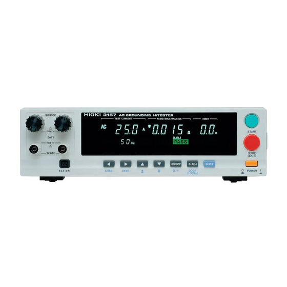
Using a constant current system, the HIOKI 3157 provides stable output current. The unit is capable of accurate four-terminal measurement. The comparator function, timer function, and screening function permit simple testing, conforming to technical standards and regulations. -
Page 11: Features Of The 3157
(1) Simple testing procedures conforming to technical standards This unit incorporates a constant current method to provide stable output current. Voltage drop is measured with four terminals. The 3157 is also equipped with a function timer and a screening function, using maximum and minimum values, allowing straightforward testing in conformance with applicable technical standards. -
Page 12: Names And Functions Of Parts
To display the flashing cursor again, press the key. The cursor appears, displaying the preset current value. Main power switch Powers the 3157 on or off. Stand The 3157 can be tilted up by using this stand. ──────────────────────────────────────────────────── 1.3 Names and Functions of Parts... - Page 13 ──────────────────────────────────────────────────── Rubber keys (in READY state) Left/Right cursor key Moves the flashing cursor. The switching range is preset before shipment: Preset current value Maximum Test Value Testing time Output Frequency. The key can be set to shift to the minimum test value and the test data count, when these values are set with the optional functions.
- Page 14 Connect the grounded three-core power cord supplied here. Integrated with a fuse holder. External I/O terminal For output of 3157 state and input of start and stop signals. Interface slot Expansion slot for installation of the optional 9593-02 RS-232C INTERFACER or 9518-02 GP-IB INTERFASE board.
- Page 15 ──────────────────────────────────────────────────── 9296 CURRENT PROBE Alligator clip Clipped to the measured object. Current output plug Connected to the unit's current output terminal. Banana-type voltage measurement plug Connected to the unit's voltage measurement terminal. 9297 CURRENT APPLY PROBE Push switch External switch equivalent for the keys.
- Page 16 ──────────────────────────────────────────────────── REMOTE CONTROL BOX 9613 REMOTE CONTROL BOX (SINGLE) 9614 REMOTE CONTROL BOX (DUAL) OPERATE switch Used to enable remote-control operation. When this switch is ON, the START and STOP keys for remote control are active. START key Works in the same manner as the key on the unit.
-
Page 17: Chapter 2 Testing Arrangements
──────────────────────────────────────────────────── Chapter 2 Testing Arrangements 2.1 Power Cord Connection The 3157 and the 3157-01 use different rated power voltages. Before WARNING turning the product on, make sure the source voltage matches that indicated on the product's power connector. Connection to an improper supply voltage may damage the product and present an electrical hazard. -
Page 18: Powering On And Off The Unit
──────────────────────────────────────────────────── 2.2 Powering on and off the Unit Before turning the product on, make sure the source voltage matches WARNING that indicated on the product's power connector. Connection to an improper supply voltage may damage the product and present an electrical hazard. -
Page 19: Probe Connection
──────────────────────────────────────────────────── 2.3 Probe Connection To avoid shock and short circuits, turn off all power before WARNING connecting probes. To avoid electrical accidents, confirm that all connections are secure. The increased resistance of loose connections can lead to overheating and fire. The 9296 CURRENT PROBE (with alligator clip) and 9297 CURRENT APPLY PROBE are available as optional probes. -
Page 20: Short Bar Connection
──────────────────────────────────────────────────── 2.4 Short Bar Connection To avoid shock and short circuits, turn off all power before WARNING connecting probes. To avoid electrical accidents, confirm that all connections are secure. The increased resistance of loose connections can lead to overheating and fire. -
Page 21: Connecting The Remote Control Box
──────────────────────────────────────────────────── 2.5 Connecting the REMOTE CONTROL BOX To avoid shock and short circuits, turn off all power before connecting WARNING probes. NOTE To prevent malfunctions, do not remove the remote-control box following startup. Before removing it, be sure to turn OFF the power. Connection of the remote-control box (9613/9614) enables start/stop operations to be performed easily. -
Page 22: Installation Site And Position
──────────────────────────────────────────────────── 2.6 Installation Site and Position Place on a stable, flat surface, using the four-footed stand. Orienting the unit vertically will block its air outlet, greatly increasing the risk of overheating. In positioning the unit, make sure the air inlet and outlet are kept open. Stand Left side view Right side view... -
Page 23: Connection To The Measured Object
──────────────────────────────────────────────────── 2.7 Connection to the Measured Object To avoid burns, never touch the output current terminal, probe tip, or WARNING contact point while testing (i.e., in TEST state). Take particular care to avoid touching the tip of the current ... -
Page 24: Connection To The 3155 Leak Current Hitester
Attaching optional 9593-02 RS-232C INTERFACE to 3157 enables testing when connected with 3155. 3155 sends command to 3157 to start testing and receives test results when the 3157 testing is complete. The test results can be saved and printed together with the 3155 leakage current test results. -
Page 25: Pre-Operation Inspection
In this case, the damage on the cable connecting to the voltage measurement terminal (the SENSE terminal) will affect the measurement values. The 3157 cannot detect the open circuit of this voltage measurement cable when performing four-terminal measurement. So, please follow the pre-operation inspection below. -
Page 26: Chapter 3 Testing Method
──────────────────────────────────────────────────── Chapter 3 Testing Method This chapter describes the procedural flow for testing, making settings, and proper testing procedure. Read Chapter 2, "Testing Arrangements" and make the necessary arrangements for testing. Press to display the Optional function setting screen. SHIFT STOP Setting the optional functions allows testing under various conditions. -
Page 27: Procedural Flow For Testing And Setting Parameters
──────────────────────────────────────────────────── 3.1 Procedural Flow for Testing and Setting Parameters The 3157 is in one of four states: READY state The unit is ready for starting a test. The lamp is turned on. READY To enter TEST state, press the key while in READY state. - Page 28 ──────────────────────────────────────────────────── TEST state This state indicates that a test is underway. The lamp is turned on. The current preset in the TEST READY state is output. The current output value, a decrease in voltage, and resistance are measured and displayed. The measured values are compared against the comparator values preset in the READY state.
-
Page 29: Making Testing Arrangements (In Ready State)
──────────────────────────────────────────────────── 3.2 Making Testing Arrangements (in READY State) Make testing arrangements in READY state, including test parameter settings, key- locking, and zero adjustment. Saving and loading for setting data and the setting of optional functions are made following the READY state. The lamp remains READY lit to indicate READY state. -
Page 30: Setting Output Current Values
──────────────────────────────────────────────────── 3.2.1 Setting Output Current Values (1) If no flashing cursor is displayed in the READY state, press either the key or key to display the cursor while the output current value is lit. (2) Change output current values using the keys. -
Page 31: Setting The Testing Time
──────────────────────────────────────────────────── The minimum test value can be set using the minimum test value setting function (see Section 4.4). Once a minimum test value is set, both minimum and maximum values are provided for resistance or voltage. To set a minimum test value, activate the optional minimum test value setting function. -
Page 32: Setting The Output Current Frequency (In Ready State)
──────────────────────────────────────────────────── The endless timer function allows continuous testing regardless of the testing time set (see Section 4.5). The test automatically stops after the lapse of 999 s while the testing time setting NOTE can be disabled by using the key. ON/OFF 3.2.4 Setting the Output Current Frequency (in READY State) If the optional test data count function is activated, the output current frequency is... -
Page 33: Initial Settings For Optional Functions
Settings are made by changing the number by using the keys. For more information on the settings, see Chapter 4, "Optional Functions." 10 11 The optional functions of the 3157 are factory-preset to the following settings: Setting item Initial setting Switching the output current... -
Page 34: Zero Adjustment Function
──────────────────────────────────────────────────── 3.4 Zero Adjustment Function Measurements may be affected by a voltage drop in the probe. Zero adjustment is necessary for accurate measurement, especially when measuring with two terminals using the short bar. The 0ADJ lamp is lit while the zero adjustment function is active. -
Page 35: Key-Lock Function
──────────────────────────────────────────────────── 3.5 Key-lock Function This function is used to keep lock the current set values. It inactivates all keys except the key, key, and the resistance/voltage switch. The START STOP KEYLOCK lamp is lit while the key-lock function is active. Key-lock indicator Setting and inactivating the key-lock function To activate the key-lock function, press... -
Page 36: Examples Of Settings
──────────────────────────────────────────────────── 3.6 Examples of Settings Output current value set: 25.0 A, Maximum test value: 0.100 Ω, Testing time: 1 minute. Assume that "0: not set" is selected for "Minimum test value setting," "Timer setting," and "Test data count" on the optional functions. The following provides an example of changing set values. - Page 37 ──────────────────────────────────────────────────── When the voltage indicator is displayed, or to set in a voltage value, first switch to the resistance indicator, then set the maximum and minimum test values. Press (Ω/V) to switch between resistance and voltage SHIFT ON/OFF indicators. (3) Setting the testing time Using the key, move the flashing cursor to the testing time.
-
Page 38: Starting A Test
──────────────────────────────────────────────────── 3.7 Starting a Test To avoid electrical accidents, confirm that all connections are secure. WARNING The increased resistance of loose connections can lead to overheating and fire. To avoid burns, never touch the output current terminal, probe tip, or ... - Page 39 ──────────────────────────────────────────────────── Forcible ending of a test To perform forcible ending of a test, press the key. This stops current STOP output, and the unit enters READY state. No screening operation is performed. The value at which to forcibly end the test can be held using the hold function (see Section 4.3).
- Page 40 ──────────────────────────────────────────────────── Measurement range Load resistance Open terminal voltage 6 V line Maximum output power 130 VA line At an output of 6 A, 6 (V) / 6 (A) = 1.0 (Ω) from the 6 V line At an output of 25 A, 130 (VA) / 25 ) = 0.208 (Ω) from the 130 VA line...
-
Page 41: Testing (In Test State)
──────────────────────────────────────────────────── 3.8 Testing (in TEST State) TEST state indicates that the unit is performing a test. Be careful not to cause electrical shock by touching the terminal or other parts though which the current (the value of which has been set in READY state) is passing. Measured current value Indicates the current value being output. -
Page 42: Screening (In Pass State)
──────────────────────────────────────────────────── 3.9 Screening (in PASS State) The unit enters PASS state when either the maximum or minimum test value is set, and when the test is completed. The lamp lights while in PASS state, PASS displaying the value established at the end of the testing period. The PASS state screen is displayed for about 0.5 second before the unit resumes READY state. -
Page 43: Screening (In Fail State)
──────────────────────────────────────────────────── 3.10 Screening (in FAIL State) The unit enters FAIL state if the measured value deviates from the maximum (or minimum) test value set. The FAIL state indicates the time at which the measured value deviated from the maximum (or minimum) value. The lamp lights together with the FAIL UPPER... -
Page 44: Chapter 4 Optional Functions
──────────────────────────────────────────────────── Chapter 4 Optional Functions Setting the optional functions allows testing under various conditions. Settings can be made for the following eleven optional functions. One number is assigned to each function. Settings are made by changing the number by moving the cursor key. - Page 45 ──────────────────────────────────────────────────── The following describes the numbers corresponding to the functions. For additional information, see Section APPINDIX 2, "Table of Optional Functions." Switching the output current frequency Switches output current frequencies (50 Hz or 60 Hz). When the test data count is at "0: Not set," the frequency is displayed in the READY state.
- Page 46 ──────────────────────────────────────────────────── Buzzer setting The buzzer ON/OFF may be set in the PASS, FAIL, error state, and other states. Selection 0: ON at screening, ON at error 1: OFF at screening, OFF at error 2: OFF at screening, ON at error 3: ON at screening, OFF at error Changing the current value in TEST state In TEST state, the current value can be changed during output by pressing the...
-
Page 47: Switching The Output Current Frequency
──────────────────────────────────────────────────── 4.1 Switching the Output Current Frequency Changes the output current frequency. When the optional test data count function is set to "1: Not set," the output current frequency set in the READY state is displayed and can be changed. If you change the frequency in the READY state, the output current frequency can be changed automatically in the optional function setting screen. -
Page 48: Pass/Fail Hold Function
──────────────────────────────────────────────────── 4.2 PASS/FAIL Hold Function If the maximum or minimum value has been set, this function retains the value for the PASS or FAIL state on test completion. If the PASS or FAIL hold function is not selected, the test result is displayed for approximately 0.5 seconds for PASS and approximately 1 second for FAIL before the unit reverts to the READY state. -
Page 49: Hold Function
──────────────────────────────────────────────────── 4.3 HOLD Function If a test is conducted with both the maximum test value and the minimum test value turned off, the unit enters the READY state as soon as test time elapses (after the lapse of 999 s if the testing time is set to OFF), or if the test is aborted with the key. - Page 50 ──────────────────────────────────────────────────── Differences between PASS/FAIL hold and hold functions ・ Unless the test reference value is set, PASS/FAIL screening is not performed. ・ If a test is conducted with both the maximum test value and the minimum test value turned off, the unit enters the READY state as soon as test time elapses (after the lapse of 999 s if the testing time is set to OFF).
-
Page 51: Setting The Minimum Test Value
──────────────────────────────────────────────────── 4.4 Setting the Minimum Test Value If the minimum test value is set to "0: Not set," the flashing cursor does not move to the minimum test value, thus disabling test settings. If the minimum test value is set to "1: Set," both maximum and minimum test values may be set. -
Page 52: Endless Timer Function
──────────────────────────────────────────────────── 4.5 Endless Timer Function In setting the endless timer, if "1: Set" is selected, currents are continually output in the TEST status regardless of the test time elapsed. In the READY state "- - -" is displayed for the test time, and the cursor stops moving to "Test Time." To end the test, the unit must enter the FAIL state or the key must be STOP... -
Page 53: Test Data Count Function
──────────────────────────────────────────────────── 4.6 Test Data Count Function Use the test data count function to display the number of test data. The test begins with "the number of test data: 1." The number increments by one each time a test completes. Once the maximum number of data is attained, counting restarts at "1."... -
Page 54: Buzzer Setting
──────────────────────────────────────────────────── 4.7 Buzzer Setting The buzzer function is enabled in PASS or FAIL state, or when an error occurs with setting or key operation. When the buzzer is set to ON, the sound of the buzzer cannot be controlled. The sound is disabled when the buzzer is set to OFF. -
Page 55: Changing The Current Value In Test State
──────────────────────────────────────────────────── 4.8 Changing the Current Value in TEST State Selecting "1: Changeable" makes it possible to change the output current value during testing in 0.1 A increments, using the keys. To change the value by 1.0 A, press keys. SHIFT The output current value can be set from 3.0 A to 31.0 A. -
Page 56: Momentary Out
──────────────────────────────────────────────────── 4.9 Momentary OUT The momentary OUT function allows current output only while the key is START held down. Releasing the key is equivalent to pressing the START STOP and ends the test. Keep the key depressed until the test time elapses. After the test time START elapses, the unit enters the READY or PASS state, depending on the optional settings. -
Page 57: Trigger Operation With Switching Probe
──────────────────────────────────────────────────── 4.9.1 Trigger Operation with Switching Probe When in the READY state, the push switch performs the same functions as the key. START When not in the READY state, the push switch performs the same functions as the key. Pressing the push switch in the TEST state is equivalent to pressing STOP key and ends the test. - Page 58 ──────────────────────────────────────────────────── (2) When the test is aborted: 1. To start the test, press the push switch while in the READY state. 2. The test is aborted if the push switch is pressed before the preset test time elapses, with the unit then entering the READY state. 3.
-
Page 59: Momentary Out Operation With Switching Probe
──────────────────────────────────────────────────── 4.9.2 Momentary OUT Operation with Switching Probe The momentary OUT function allows current output only while the push switch is held down. Releasing the push switch is equivalent to pressing the key and STOP ends the test. A test ends when the test time elapses, even if the push switch is held down. Depending on the settings, the unit enters either the READY or PASS state. - Page 60 ──────────────────────────────────────────────────── (2) When the test is aborted: 1. To start the test, press the push switch while in the READY state. The TEST state is maintained as long as the push switch is held down. 2. The test is aborted if the push switch is released before the preset test time elapses, with the unit then entering the READY state.
- Page 61 ──────────────────────────────────────────────────── (2) When the tested sample fails the test: 1. To start the test, press the push switch while in the READY state. 2. Hold down the push switch for the duration of the test. The unit enters the FAIL state.
-
Page 62: Setting The Test Mode
──────────────────────────────────────────────────── 4.10 Setting the Test Mode Soft start mode, normal mode and continuous test mode can be set. Setting procedure (1) Press while in READY state to display the Optional function SHIFT STOP setting screen. (2) Use the keys to move the flashing cursor to the position shown in the figure. - Page 63 ──────────────────────────────────────────────────── Flow of operation in Soft start mode ・ Press the STOP key to abort a test. ・ More than 30 seconds Press the START key to start a test. elapse. The unit enters the stand-by state (as indicated by a blinking TEST lamp).
-
Page 64: Normal Mode
──────────────────────────────────────────────────── 4.10.2 Normal Mode Select normal mode if the anticipated load resistance is 0.200 Ω or greater. In normal mode, press the key in READY state while the soft start START function is in the stand-by state (as indicated by a blinking lamp). -
Page 65: Continuous Test Mode
──────────────────────────────────────────────────── 4.10.3 Continuous Test Mode Unlike the soft start mode, the continuous test mode places the unit into the hold state if the probe is detached from the measured object, suspending output. To restart the test, cancel the hold state and connect the probe to the measuring object. (1) Set the appropriate parameters in the READY state. - Page 66 ──────────────────────────────────────────────────── Flow of operation in Continuous test mode ・Press the STOP key to abort a test. ・More than 30 seconds Press the START key to start a test. elapse. The unit enters the stand-by state (as indicated by a blinking TEST lamp).
-
Page 67: Printer Output
──────────────────────────────────────────────────── 4.11 Printer Output You can print test parameters and results with the optional 9442 PRINTER. This printer offers the following two print modes. When "0: Not used" is selected, the printer will not print, even if connected. When "1: Automatically print for PASS/FAIL screening" is selected, press the key for about two seconds in the READY state to print the test results. - Page 68 "---" is printed if the optional endless timer function is set to "1: Set." Maximum number of test data (Not printed for OFF) MAX DATA # Test result printing HIOKI 3157 Model name GROUNDING This is printed if the test data count function is not used or HiTESTER if the number of test data is 1.)
-
Page 69: Example Of Optional Function Settings
──────────────────────────────────────────────────── 4.12 Example of Optional Function Settings We assume that the 3157 is in the READY state and that the minimum test value setting function and the test data count function are inactive. The following example shows how to set the number of test data to "5," after activating the minimum test value setting and test data count functions. - Page 70 ──────────────────────────────────────────────────── (4) Next, using the keys, change "Test data count" from "0: Set" to "1: Not set." In "Test data count," change the sixth number from the left to "1." When "Test data count" is activated, the screen shifts to allow you to set a maximum value for the number of test data.
-
Page 71: Example Of Optional Functions Use
──────────────────────────────────────────────────── 4.13 Example of Optional Functions Use The following describes how 3157 optional functions are used in testing. Varying combinations of optional functions are available for testing. (1) Testing to check test results, using the 3157 Optional function settings Optional function... - Page 72 ──────────────────────────────────────────────────── (3) Continuous test mode using the 9297 CURRENT APPLY PROBE Optional function settings Optional function Selection PASS/FAIL hold function : PASS not held, FAIL not held Hold function : Not held Test data count function : Set Test mode : Continuous test mode Printer output : Automatically print for...
- Page 73 ──────────────────────────────────────────────────── Chapter 5 Saving/loading Preset Values 5.1 Saving Preset Values The following describes a function used to save values set in the READY state. Up to twenty parameters may be saved. To retrieve saved data, follow the procedures described in Section 5.2, "Loading Preset Values." Preset current value Shows the preset current value for the set data being displayed.
-
Page 74: Saving Preset Values
──────────────────────────────────────────────────── 5.1.1 Procedure for Saving Data To select a preset value to be saved, the unit must be in the READY state. Preset values cannot be changed in the save screen. The following six parameters may be saved: 1. Preset current value 2. -
Page 75: Example Of Saving
──────────────────────────────────────────────────── 5.1.2 Example of Saving The following example shows how to save in File No.3. We assume that the 3157 is in the READY state. (1) In the READY state, set the preset value to save. For more information on making these settings, see Chapter 3, "Testing Method."... - Page 76 ──────────────────────────────────────────────────── (3) Use the keys to select File No.3. This example shows File No. 1. Press the key twice to display File No.3. (4) Use the keys to check maximum and minimum test values. In this example, File No. 3 contains the following settings. Preset current value 30.0 A Maximum test value 3.00 V Minimum test value 0.09 V...
- Page 77 ──────────────────────────────────────────────────── 5.2 Loading Preset Values The following describes how to load saved data. Twenty preset values may be saved. Use this function to instantly change a preset value. Preset current value Shows the preset current value for the set data being displayed. Maximum value icon and minimum value icon The symbol appears when the maximum test value is displayed, and the symbol...
-
Page 78: Loading Preset Values
──────────────────────────────────────────────────── 5.2.1 Procedure for Loading Data Before loading, carefully read Section 5.1, "Saving Preset Values" and prepare the data to be saved. The following are factory-set data. Preset current value 25.0 A Maximum test value 0.100 Ω (2.5 V) Minimum test value OFF (OFF) Testing time 60.0 s... -
Page 79: Example Of Loading
──────────────────────────────────────────────────── 5.2.2 Example of Loading The following example shows how to load File No.3. We assume that the 3157 is in the READY state. (1) Press to bring up the load screen. SHIFT In the load screen, the value set in the READY state is replaced by the saved data being displayed. - Page 80 ──────────────────────────────────────────────────── (3) Use the keys to check maximum and minimum test values. In this example, File No. 3 contains the following settings. Preset current value 30.0 A Maximum test value 2.00 V Minimum test value 0.10 V Testing time 5.0 s (4) To load the data, press .
- Page 81 ──────────────────────────────────────────────────── Chapter 6 External I/O Both output signals regarding the status of the 3157 (e.g., READY state) and input signals to the key and the key are controlled through the external START STOP I/O terminal, located at the back of the unit.
-
Page 82: Chapter 6 External I/O
──────────────────────────────────────────────────── 6.1 Signal Line The following external I/O connectors are used. Connector of the 3157 main unit DDK Ltd.'s 57RE-40360-730B(D29) 36-pin receptacle Compatible connector DDK Ltd.'s 57-30360, 57E-30360, 57F-30360 and 57FE-30360 Hirose Electric's RC30-36P 36-pin ・・・1 18・・・ ・・・19 36・・・ External I/O connector pin numbering... -
Page 83: Signal Line
──────────────────────────────────────────────────── Function of the signal line Signal line name Function _________ LO in the READY state READY _________ LO in the FAIL state at LOWER (minimum value) L-FAIL _________ LO in the FAIL state at UPPER (maximum value) U-FAIL _______ LO in the PASS state PASS _______... - Page 84 ──────────────────────────────────────────────────── The insulation of the signal lines is for eliminating mutual influences between the signals. Any external device which is connected to the 3157 unit should always be properly protectively grounded. If proper connection to a protective ground is not established, there is a danger of damage to the insulation.
- Page 85 GND. The maximum current capacity is 100 mA. Do not connect any external circuit whose current consumption is greater than 100 mA. INT GND is grounded to the chassis of the 3157 unit. ・The output signal status upon power-on may be undetermined. Care should be taken in the operation of equipment connected to the external I/O.
- Page 86 ──────────────────────────────────────────────────── 6.2 Timing Chart of External I/O Terminal (1) Timing chart at time of start of testing ____________ _________ When a test starts, the READY signal indicates HI and the TEST signal indicates _________ The TEST signal changes according to the indicator on the fluorescent TEST display, indicating LO at zero adjustment as well as during testing.
-
Page 87: Timing Chart Of External I/O Terminal
──────────────────────────────────────────────────── __________ READY ________ TEST ________ PASS _________ U-FAIL _________ L-FAIL (3) Timing chart when testing is aborted No test determination is returned if the key is pressed to abort testing, or if STOP the testing duration passes without settings for maximum test value or minimum test value. - Page 88 ──────────────────────────────────────────────────── ──────────────────────────────────────────────────── 6.2 Timing Chart of External I/O Terminal...
-
Page 89: Chapter 7 Maintenance, Inspection And Ultimate Disposal
Hioki representative. ・ Pack the product carefully so that it will not be damaged during shipment, and include a detailed written description of the problem. Hioki cannot be responsible for damage that occurs during shipment. ・ If the unit has been subject to moisture, or if oil and dust have accumulated in the unit interior, the danger of electrical shock or fires resulting from the deterioration of insulation increases greatly. -
Page 90: Fuse Replacement
──────────────────────────────────────────────────── Cleaning ・ To clean the product, wipe it gently with a soft cloth moistened with water or mild detergent. Never use solvents such as benzene, alcohol, acetone, ether, ketones, thinners or gasoline, as they can deform and discolor the case. 7.2 Fuse Replacement To avoid electric shock, turn off the power switch and disconnect the ... -
Page 91: Troubleshooting
・ If the unit was damaged in transit. 7.4 Displaying Errors If an error occurs, the 3157 displays the following on the screen. When errors other than the above are displayed, the unit may be malfunctioning. Contact your dealer or Hioki representative. -
Page 92: Resetting The System
──────────────────────────────────────────────────── 7.5 Resetting the System Resetting the system While pressing the key, press the main power switch to turn on power. SHIFT Parameters after resetting the system When the system is reset, the following parameters are initialized. (1) Testing set values and saved data Preset current value 25.0 A Maximum test value... -
Page 93: Ultimate Disposal (Removal Of The Lithium Battery)
Procedure (1) Turn OFF the power switch, and disconnect the power cord and probe. (2) Remove the four feet (fastened with eight screws) at the back of the 3157 and the two screws on the handle on the right side. -
Page 94: External Dimensions
──────────────────────────────────────────────────── 7.7 External Dimensions 3 2 0 ±2 3 4 ±1 2 5 ±5 2 6 3 ±2 ──────────────────────────────────────────────────── 7.7 External Dimensions... -
Page 95: Specifications
──────────────────────────────────────────────────── Chapter 8 Specifications 8.1 Basic Specifications Current generator Current generating method PWM constant current control Current preset range 3.0 A to 31.0 AAC (resolution of 0.1 A) at a resistance of 0.1 Ω. (1% of setting + 0.2 A) Load of 0.1 Ω * , within maximum output Current preset accuracy power. -
Page 96: Chapter 8 Specifications
──────────────────────────────────────────────────── Timer * ON preset : Displays remaining time by counting down from the preset time OFF preset : Displays elapsed time 0.5 s to 999 s Setting range Setting resolution 0.1 s (0.5 s to 99.9 s), 1 s (100 s to 999 s) Timer accuracy 50 ms (0.5 s to 99.9 s)... -
Page 97: General Specifications
Approx. 10 years (at 25 reference value) Backup battery lifetime Rated power voltage range 100 to 120 VAC (3157), 100 to 120 VAC/ 200 to 240 VAC (3157-01) (Voltage fluctuations of 10% from the rated supply voltage are taken into account.) -
Page 98: General Specifications
──────────────────────────────────────────────────── 9296 CURRENT PROBE Rated voltage 30 VAC or 60 VDC 30 AAC or 30 ADC Rated current 400 VAC, 1 mA, 1 minute Dielectric strength Test point Between current and voltage, and coated cable Operating temperature and 0 to 40 (32 to 104 ), 90%RH max. - Page 99 *9443-01 AC ADAPTER (for Japan) *9443-02 AC ADAPTER (for EU) ・ The 9442 is shipped with the function settings for use with the HIOKI 3166 NOTE CLAMP ON POWER HiTESTER. Before using, always change the settings of the DIP switches.
- Page 100 APPENDIX2 ──────────────────────────────────────────────────── Appendix 1.2 Probe The 9296 CURRENT PROBE (with alligator clip) and 9297 CURRENT APPLY PROBE are available. Use two sets of the 9296 or a single combined set of 9296 and 9297. An external switch can be used for the 9297 CURRENT APPLY PROBE. 9296 CURRENT PROBE 9297 CURRENT APPLY PROBE Appendix 1.3 9613 REMOTE CONTROL BOX (SINGLE)
- Page 101 APPENDIX3 ──────────────────────────────────────────────────── Appendix 1.4 9614 REMOTE CONTROL BOX (DUAL) Unlike the 9613, the 9614 REMOTE CONTROL BOX (DUAL) has two START keys. Pressing both keys is equivalent to pressing the START key on the unit. By using the Momentary-OUT function in Optional Functions, the 9614 allows the control box to be used with both hands, thus ensuring safer testing.
- Page 102 APPENDIX4 ──────────────────────────────────────────────────── Appendix 2 Table of Optional Functions The following shows the optional functions. For more information on settings, see Chapter 4, "Optional Functions." 10 11 Optional function Selection (1) Switching the output current 0: 50 Hz frequency 1: 60 Hz (2) PASS/FAIL hold function 0: PASS not held, FAIL held 1: PASS held, FAIL held...
- Page 103 APPENDIX5 ──────────────────────────────────────────────────── Appendix 3 Standards Information current as of June 2005. Provided for reference. For more details, please refer to the latest version of the standards. Specifications for this product do not necessarily meet all the required standards. Use this product after confirming its measurement range. (See Section 3.7, "Starting a Test") Medical electrical equipment - Part1: General requirements for safety (IEC60601-1(1988-12)+am1(1991-11)+am2(1995-03)
- Page 104 APPENDIX6 ──────────────────────────────────────────────────── Household and similar electrical appliances - Safety - Part1: General requirements(IEC60335-1(2001-05)+am1(2004-03)) Type test: "27. Provision for earthing" Test current: A current derived from a source having a no-load voltage not exceeding 12 V(a.c. or d.c.) and equal to 1.5 times rated current of the appliance or 25 A, whichever is higher.
- Page 105 APPENDIX7 ──────────────────────────────────────────────────── If the current rating of the circuit under test exceeds 16 A ・for a.c. powered equipment Test current: Two times the current rating of the circuit under test Test time: 2 min Test point: Between the main protective earthing terminal and the point in the equipment that is required by 2.6.1 to be earthed Allowable range: The voltage drop across the PROTECTIVE BONDING CONDUCTOR shall not exceed 2.5 V...
- Page 106 APPENDIX8 ──────────────────────────────────────────────────── ・for d.c. powered equipment Test current: Specified by the manufacturer Test time: Specified by the manufacturer Test point: Between the main protective earthing terminal and the point in the equipment that is required by 2.6.1 to be earthed Allowable range: The voltage drop across the PROTECTIVE BONDING CONDUCTOR shall not exceed 2.5 V The test current can be either a.c.
- Page 107 APPENDIX9 ──────────────────────────────────────────────────── ROUTINE TESTS: "Annex F (normative) ROOUTINE TESTS" The manufacturer shall perform the tests of F.1 to F.3 on 100% of equipment produced which has both HAZARDOUS LIVE parts and ACCESSIBLE conductive parts. F.1 Protective earth Test current: No value is specified for the test current. Test time: No description Test point:...
- Page 108 INDEX 1 _____________________________________________________________________________________________ Index - A - - F - Alligator clip FAIL hold function 41,43 FAIL state 21,36 - B - File number 67,68,71 Flashing cursor 4,22,37 Banana-type voltage measurement plug 6,11 Forcible ending Buzzer 20,26,38,47,86,APPENDIX4 Four-terminal measurement Fuse 84,85 - C - - H -...
- Page 109 INDEX 2 _____________________________________________________________________________________________ - M - - S - Maximum number of test data Save Maximum test value Short bar 23,68,72,86 Maximum value icon Soft start mode 34-36,67,71 26,39,55,86,APPENDIX4 Measured current value Stand 34-36 3,14 Measured resistance value Stand-by state 34-36 31,55,58 Measured voltage value...
Need help?
Do you have a question about the 3157 and is the answer not in the manual?
Questions and answers