Hioki 3169-21 Quick Start Manual
Clamp on power hitester
Hide thumbs
Also See for 3169-21:
- Instruction manual (224 pages) ,
- Quick start manual (40 pages) ,
- Instruction manual (82 pages)
Table of Contents
Advertisement
Quick Links
Download this manual
See also:
Instruction Manual
Advertisement
Table of Contents

Related Manuals for Hioki 3169-21


Summary of Contents for Hioki 3169-21
- Page 1 QUICK START MANUAL 3169-20/21 CLAMP ON POWER HiTESTER...
-
Page 3: Table Of Contents
Contents Contents Introduction ..............1 Safety Notes ..............1 1 Parts Names Instrument Labels and Functions ....... 4 Screen Names and Display Elements ....8 1.2.1 Screen Configuration ...........8 1.2.2 Common Display ..........9 1.2.3 On-Screen Indicators .........10 2 Power Measurement Outline .............. - Page 4 Quick Start Manual Contents...
-
Page 5: Introduction
Introduction • The 3169-20/21 CLAMP ON POWER HiTESTER is supplied with a instruction manual in addition to this manual. Please be sure to read both manuals. • This manual is a quick reference source with examples and infor- mation regarding the setting-up of and key operation for the 3169-20/21 CLAMP ON POWER HiTESTER for measurement purposes. - Page 6 Quick Start Manual...
-
Page 7: Parts Names
Parts Names ❖4 "Connecting to Lines to be Measured" (page 35) ❖11 "Using D/A Output (3169-21 only)" (page 157) Recorder, logger ❖10 "Using the External Input/ Output Terminal" (page 151) D/A output (3169-21) ❖9 "Using the Instrument with EXT I/O a Computer"... -
Page 8: Instrument Labels And Functions
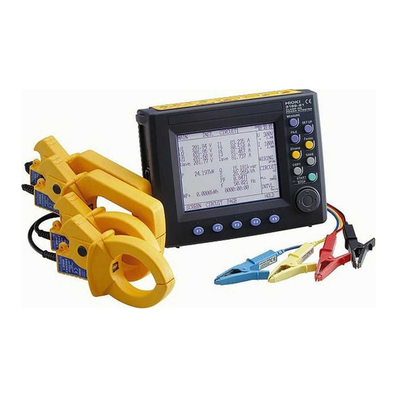
Quick Start Manual 1.1 Instrument Labels and Functions 1.1 Instrument Labels and Functions Front Panel Display 5.7-inch STN LCD Cursor key Function (F1-F5) keys These keys move the cur- Selects or switches the screens sor on the screen. and setting items. - Page 9 1.1 Instrument Labels and Functions Front Panel Enhanced View MEASURE key Switches to a screen that displays measurements. SET UP key Switches to a screen that displays settings. FILE key Used to work on files. I RANGE key Sets the current measurement range for the circuit to be measured on-screen.
- Page 10 Quick Start Manual 1.1 Instrument Labels and Functions Top Panel Voltage Input terminals Connect the supplied 9438-03 VOLTAGE CORD. Black Red Yellow Blue CH1 CH2 CH3 CH4 Current Input terminals Connect an optional clamp-on sensor. Left Panel KEY LOCK switch Contrast Control Knob Sliding this switch in the direction of the (CONTRAST)
- Page 11 Connects to a PC or printer using A PC Card can be an RS-232C cable. inserted here. D/A Output Terminal (D/A OUT) Installed in the 3169-21 only. Connects the sup- plied 9441 connection ca- ble. Used for analog output. Eject button...
-
Page 12: Screen Names And Display Elements
FILE Measurement screen MAIN POWER INTEGRATE DEMAND ZOOM HARMONIC LIST HARMONIC GRAPH WAVEFORM WIRING CHECK WIRING DIAGRAM File screen Setting screen INTERNAL SETTINGS MEASUREMENT INTERNAL MEMORY DATA OUTPUT PC CARD SAVE, PRINT ITEMS FIRMWARE UPDATE SYSTEM D/A OUTPUT (3169-21 only) -
Page 13: Common Display
1.2 Screen Names and Display Elements 1.2.2 Common Display This section of the screen shows information common to all mea- surement screens (except the zoom screen and the wiring diagram screen). Common Display Time Range Wiring No. of circuits Synchroniza- tion method Interval Time... -
Page 14: On-Screen Indicators
Quick Start Manual 1.2 Screen Names and Display Elements 1.2.3 On-Screen Indicators Goes on when the reactive-power-meter method is Goes on when the displayed measurement is held. Goes on when the medium for saving data is set to PC card. Flashes when the PC card is accessed. Goes on when the medium for saving data is set to internal memory. -
Page 15: Power Measurement
2.1 Outline Power Measurement 2.1 Outline This chapter explains setting and measurement procedures using the following conditions. Measure the power of a Three-phase 3-wire line for 7 days. Measurement location: A Tree-phase 3-wire 200 V line of a switchboard (50 Hz, 50 A load) Setting: Time-series measurement start time: 2002/06/20 08:00 Time-series measurement stop time: 2002/06/27 08:00... - Page 16 Quick Start Manual 2.1 Outline Setting Screens under the Example Conditions <MEASUREMENT> WIRING : 3P3W2M (Three-phase 3-wire, 2-power-meter method) Number of circuits : X 1 (1 circuit) SAMPLING : PLL Measured frequency: 50 Hz VAR METHOD : OFF AVERAGE TIMES : 1 VOLTAGE RANGE : 300 V VT (PT) : 0001.00...
-
Page 17: Measurement Procedure
2.2 Measurement Procedure 2.2 Measurement Procedure 1. Connecting the Power Cord Measurement Preparations 2. Connecting the Voltage Cords (page 14) 3. Connecting the Clamp-On Sensor 4. Inserting a PC Card 5. Turning the Power On 1. Setting the wiring details Connect to the Line to be 2. -
Page 18: Measurement Preparations
Quick Start Manual 2.3 Measurement Preparations 2.3 Measurement Preparations 1. Connecting the Power Cord • Before turning the product on, make sure the source volt- age matches that indicated on the product's power connec- tor. Connection to an improper supply voltage may damage the product and present an electrical hazard. - Page 19 2.3 Measurement Preparations 2. Connecting the Voltage Cords Connect the voltage cords to the product first, and then to the active lines to be measured. Observe the following to avoid electric shock and short circuits. • Voltage cord should only be connected to the secondary side of a breaker, so the breaker can prevent an accident if a short circuit occurs.
- Page 20 Quick Start Manual 2.3 Measurement Preparations 3. Connecting the Clamp-On Sensor Connect the clamp-on sensors to the product first, and then to the active lines to be measured. Observe the following to avoid electric shock and short circuits. • Clamp sensor should only be connected to the secondary side of a breaker, so the breaker can prevent an accident if a short circuit occurs.
- Page 21 2.3 Measurement Preparations 4. Inserting a PC Card Use only PC Cards sold by HIOKI. Compatibility and perfor- mance are not guaranteed for PC cards made by other manu- facturers. You may be unable to read from or save data to such cards.
-
Page 22: Connect To The Line To Be Measured
Quick Start Manual 2.4 Connect to the Line to be Measured 2.4 Connect to the Line to be Measured 1. Setting the wiring details Set the 3169-20/21 to measure a three-phase 3-wire 200 V line (50 Hz, 50 A load) using the 9661 CLAMP ON SENSOR (500 A rated). wiring (1) Set the to "3P3W2M."... - Page 23 2.4 Connect to the Line to be Measured (2) Make sure the number of circuits to be measured is set to "X1 (1 circuit)." When multiple circuits of the same voltage system (the same trans- former) are to be measured, use a preset between X2 (2 circuits) and X4 (4 circuits).
- Page 24 Quick Start Manual 2.4 Connect to the Line to be Measured (5) Make sure the displayed data averaging times is set to "1." (6) Set the voltage range to "300 V." Move the cursor to " ." VOLTAGE RANGE Select " "...
- Page 25 2.4 Connect to the Line to be Measured (8) Make sure "9661" is selected as the clamp-on sensor to be used. (9) Set the current range to "50 A." Move the cursor to " ." CURRENT RANGE Select " " using the function keys. Selectable current ranges vary according to the clamp-on sensor used.
- Page 26 Quick Start Manual 2.4 Connect to the Line to be Measured 2. Displaying the Wiring Diagram Press the key to display the measurement screen. MEASURE Press the (SCREEN) key to display the selection window. SCREEN Move the cursor to " ."...
- Page 27 2.4 Connect to the Line to be Measured 3. Connectting the voltage cords and clamp-on sensor to the line to be measured Connect the 9438-03 voltage cords and the 9661 clamp-on sensor to the line to be measured, while referring to the wiring diagram. We recommend that the color of a voltage cord be matched to that of the attached input-cord label used for the same channel.
- Page 28 Quick Start Manual 2.4 Connect to the Line to be Measured 4. Checking the Wiring Press the key to display the measurement screen. MEASURE Press the (SCREEN) key to display the selection window. SCREEN Move the cursor to " ." WIRING CHECK Press the (select) key.
- Page 29 2.4 Connect to the Line to be Measured The wiring check result is NG. The voltage input • Do the voltage clips grip the wires properly? is NG. • Is the voltage cord properly inserted into the voltage input terminal of the 3169-20/21? •...
-
Page 30: Perform Measurement
Quick Start Manual 2.5 Perform Measurement 2.5 Perform Measurement 1. Setting the measurement conditions DATA OUTPUT • Measurement start: 2002/06/20 08:00 • Measurement stop: 2002/06/27 08:00 • Data automati- cally output to the PC card at 5-minute intervals. • Data file name: INTEG SAVE, PRINT ITEMS Saves the average... - Page 31 2.5 Perform Measurement Move the cursor to " ." MEAS. START Press the (TIME) key. TIME MANUAL Measurement starts when the START/STOP key is pressed (default setting). TIME Measurement starts at the time set by users. JUST Measurement will begin as soon as the internal clock reaches a time that is evenly divisible by the set interval.
- Page 32 Quick Start Manual 2.5 Perform Measurement (3) Set the interval time to "5 minutes." Move the cursor to " ." INTERVAL TIME Press the (change) key to display the selection window. change Select " " using the cursor key. 5 min select Press the (select) key.
- Page 33 2.5 Perform Measurement (5) Set the data output file name to "INTEG." Move the cursor to " ." DATA FILE NAME Press the (change) key to display the selection window. change Enter " " using the cursor and (input) key. To make a cor- INTEG rection, press the (BS) key.
- Page 34 Quick Start Manual 2.5 Perform Measurement (6) Set the data output items Press the (NEXT SCR) key to display the save/print items set- NEXT ting screen. 256 or less 7 days or more Move the cursor to " ." NORM. MEAS. Press the (ON) key.
- Page 35 2.5 Perform Measurement 2. Confirm range Press the key to display the measurement screen. MEASURE Press the key or key to select an appropriate U RANGE I RANGE range. If you press the Key, it selects a current range with a I RANGE sufficient margin, in consideration of fluctuations in the load cur- rent of the line to be measured.
- Page 36 Quick Start Manual 2.5 Perform Measurement 4. Stop measurement The 3169-20/21 will automatically stop measurement at the stop time. The measurement data "INTEG.csv" has been saved on the PC card. Interrupt Measurement. Press the key. The message " START/STOP Do you want to stop "...
- Page 37 HIOKI 3169-20/21 CLAMP ON POWER HiTESTER Quick Start Manual Publication date: October 2003 Revised edition 2 Edited and published by HIOKI E.E. CORPORATION Technical Support Section All inquiries to International Sales and Marketing Department 81 Koizumi, Ueda, Nagano, 386-1192, Japan TEL: +81-268-28-0562 / FAX: +81-268-28-0568 E-mail: os-com@hioki.co.jp...
- Page 38 HEAD OFFICE 81 Koizumi, Ueda, Nagano 386-1192, Japan TEL +81-268-28-0562 / FAX +81-268-28-0568 E-mail: os-com@hioki.co.jp / URL http://www.hioki.co.jp/ HIOKI USA CORPORATION 6 Corporate Drive, Cranbury, NJ 08512, USA TEL +1-609-409-9109 / FAX +1-609-409-9108 3169A983-02 03-10H Printed on recycled paper...
Need help?
Do you have a question about the 3169-21 and is the answer not in the manual?
Questions and answers