Table of Contents
Advertisement
Advertisement
Table of Contents

Related Manuals for Hioki 3151


Summary of Contents for Hioki 3151
- Page 1 3151 EARTH HiTESTER INSTRUCTION MANUAL...
-
Page 3: Table Of Contents
Contents Introduction Inspection Safety Notes Notes on Use Chapter 1 Outline 1.1 Product Outline 1.2 Features 1.3 Names and Functions of Parts Chapter 2 Specifications 2.1 General Specifications 2.2 Measurement Range and Tolerances Chapter 3 Technical Information 3.1 Earthing Resistance 3.2 Measurement Principle Chapter 4 Measurement Procedure 4.1 Preparations... - Page 5 ――――――――――――――――――――――――――― Introduction Thank you for purchasing the HIOKI"3151 EARTH HiTESTER." To obtain maximum performance from the instrument, please read this manual first, and keep it handy for future reference. Inspection When you receive the instrument, inspect it carefully to ensure that no damage occurred during shipping.
-
Page 6: Safety Notes
――――――――――――――――――――――――――― Safety Notes This manual contains information and warnings essential for safe operation of the instrument and for maintaining it in safe operating condition. Before using the instrument, be sure to carefully read the following safety notes. DANGER This instrument is designed to comply with IEC 61010 Safety Standards, and has been thoroughly tested for safety prior to shipment. -
Page 7: Safety Symbols
――――――――――――――――――――――――――― Safety Symbols symbol printed on the instrument indicates that the user should refer to a corresponding topic in the manual (marked with the symbol) before using the relevant function. In the manual, the symbol indicates particularly important information that the user should read before using the instrument. - Page 8 ――――――――――――――――――――――――――― Overvoltage categories (CAT) This instrument complies with CAT II safety requirements. To ensure safe operation of measurement instruments, IEC 60664 establishes safety standards for various electrical environments, categorized as CAT I to CAT IV, and called overvoltage categories. These are defined as follows.
- Page 9 ――――――――――――――――――――――――――― Higher-numbered categories correspond to electrical environments with greater momentary energy. So a measurement device designed for CAT III environments can endure greater momentary energy than a device designed for CAT II. Using a measurement instrument in an environment designated with a higher- numbered category than that for which the instrument is rated could result in a severe accident, and must be carefully avoided.
-
Page 10: Notes On Use
――――――――――――――――――――――――――― Notes on Use Follow these precautions to ensure safe operation and to obtain the full benefits of the various functions. DANGER When measuring earthing resistance, a voltage of maximum 50 Vrms exists across the measurement terminals E - C(H). Take proper precautions against electric shock. - Page 11 Using the instrument in such conditions could cause an electric shock, so contact your dealer or Hioki representative for replacements. (Model 9215). ―――――――――――――――――――――――― Notes on Use...
- Page 12 viii ――――――――――――――――――――――――――― CAUTION Do not store or use the instrument where it could be exposed to direct sunlight, high temperature or humidity, or condensation. Under such conditions, the instrument may be damaged and insulation may deteriorate so that it no longer meets specifications.
-
Page 13: Chapter 1 Outline
――――――――――――――――――――――――――― Chapter 1 Outline 1.1 Product Outline The earthing (grounding) of electrical equipment is essential in maintaining safety and protecting lives, as well as preventing damage to equipment. This instrument uses the AC phase differential system to measure earthing resistance. This assures accurate measurements unaffected by earth voltage and auxiliary earthing resistance. -
Page 14: Features
――――――――――――――――――――――――――― 1.2 Features (1) High performance Performance of this instrument surpasses the requirements of the Japanese standard JISC- 1304-1995 and complies with the safety standard IEC 61010. (2) Wide measurement range Measurement scope was extended to 115% of the earthing resistance measurement range. This is useful especially in the 10 Ω... - Page 15 ――――――――――――――――――――――――――― (6) Over-voltage protection and warning buzzer When an AC outlet is used for simplified measurement and a voltage is input by mistake, the protection circuit is activated and a warning tone is heard. (7) Semi-dust-proof construction Measurement switches, indicators and other moving parts are designed to withstand use in tough environments.
-
Page 16: Names And Functions Of Parts
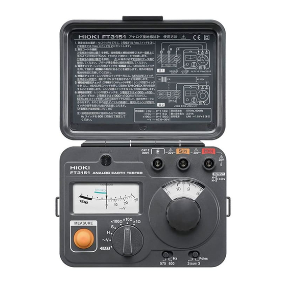
――――――――――――――――――――――――――― 1.3 Names and Functions of Parts Front View ① Measurement button ( PRESS ON Press this button for earthing resistance measurement, auxiliary earthing resistance check, and battery check. ② Range selector Serves to switch the instrument to battery check, earth voltage measurement, auxiliary earthing resistance check, and earthing resistance measurement. - Page 17 ――――――――――――――――――――――――――― ④ Resistance dial The measured resistance value can be read from this dial. ⑤ Dial knob ⑥ Galvanometer ⑦ Battery effective range ⑧ Auxiliary earthing resistance effective range ⑨ Earth voltage scale ⑩ ADJUST: Zero adjustment ⑪ E: Earth terminal This terminal is to be connected to the earth of the measurement object.
- Page 18 ――――――――――――――――――――――――――― Rear View ⑮ Fixing screw on the battery cover ⑯ Battery cover ―――――――――――――――――――――――― Chapter 1 Outline...
-
Page 19: Chapter 2 Specifications
――――――――――――――――――――――――――― Chapter 2 Specifications 2.1 General Specifications Operating system AC potentiometer Display Method Resistance indication on meter with linear scale galvanometer Open circuit voltage 50 V AC max Measurement current 15 mA AC max (using the 2-pole method: 3 mA AC max) Measurement 575 Hz (during setting to 2a or 3a) frequency... - Page 20 ――――――――――――――――――――――――――― Battery Life More than 500 times (R6P in use) or more than 1400 (LR6 in use) (30-second measurement/30-second pause cycle) Overvoltage 250 VAC for one minute protection between E-P (S) and E-C (H) terminals Insulation resistance 100 MΩ or more/500 V DC between electric circuit and case Dielectric voltage 3000 V AC for one minute...
-
Page 21: Measurement Range And Tolerances
――――――――――――――――――――――――――― 2.2 Measurement Range and Tolerances Accuracy is guaranteed for 1 year at following conditions. (Temperature and humidity: 23 5 ), 80% RH or less) Measurement Measurement range Tolerances item Earthing 10 (0 to 11.5) resistance 100 (0 to 115) 2.5%f.s. - Page 22 ――――――――――――――――――――――――――― Operating error (according to EN61557-5, 4.3:1997) The operating error is calculated by the following combination of the values of influence quantity in the operating range. Operating error 12.8% Intrinsic error / influence quantity Intrinsic error 2.5% Reference conditions Part 5, 6.1 Reference position 90 Position 5.0%...
-
Page 23: Chapter 3 Technical Information
――――――――――――――――――――――――――― Chapter 3 Technical Information 3.1 Earthing Resistance Earthing resistance measurements differ from ordinary resistance measurements, due to the factors described below. (1) Polarization Because of polarization between the earthing body and the earth ground, using a direct current for measurement is not possible. (2) Special conditions Because one pole of the earth resistance measurement object is buried in the ground, it... - Page 24 To eliminate such influences as much as possible, the 3151 uses a newly developed AC phase differential method to measure earthing resistance. This assures accurate results also under difficult conditions.
-
Page 25: Measurement Principle
――――――――――――――――――――――――――― 3.2 Measurement Principle (1) Normal measurement (3-pole method) Figure 1 shows the basic circuit principle for earthing resistance measurement. The measuring current I, driven by the oscillating voltage of the oscillator, flows through the loop formed as follows: oscillator→Rc→Rx→C.T. If the galvanometer is balanced, the voltage between the measurement terminals E - P(S) - Page 26 (Ro) to the earthing resistance of the measurement object (Rx). The 3151 uses a very low measurement current, so that the leakage current circuit breaker of a household power supply will not be tripped when the grounded side of an AC outlet is used as existing earthing body.
-
Page 27: Chapter 4 Measurement Procedure
――――――――――――――――――――――――――― Chapter 4 Measurement Procedure WARNING When the measurement button (PRESS ON) is operated, a voltage of maximum 50 Vrms AC is produced. Take proper precautions against electric shock. When using the grounded side of an AC outlet for simplified measurement, be sure to check the outlet first, to determine the grounded side. -
Page 28: Preparations
――――――――――――――――――――――――――― 4.1 Preparations (1) Zero adjustment Before use, adjust the needle of the galvanometer to the zero point. Use a small flat-blade screwdriver to turn the ADJUST control until the needle points at the center of the scale. This must be performed while the measurement button ( ) is not depressed. -
Page 29: Normal Measurement (3-Pole Method)
――――――――――――――――――――――――――― 4.2 Normal Measurement (3-Pole Method) (1) Connections Connect the measurement terminals to the measurement object using the supplied measurement leads, as shown in Figure 3. Drive the auxiliary earthing rods deep into the ground, at intervals of 5 - 10 meters (straight line) from the measurement object Measuremen Lead... - Page 30 ――――――――――――――――――――――――――― (2) Settings for 3-pole measurement Set the 2/3 pole measurement selector ) to " ". TERMINALS When using the 3-pole measurement method, NOTE measurement can be carried out with a measurement frequency of 575 Hz ( ) or 600 Hz ( ).
- Page 31 (5) Auxiliary earthing resistance check The 3151 has a function for checking the auxiliary earthing resistance. Be sure to perform this check before measuring earthing resistance.
- Page 32 ――――――――――――――――――――――――――― ① Checking earthing condition of auxiliary earthing rod Set the range selector to and press the measurement button ( ). Verify that PRESS ON the needle of the galvanometer is within the green " " range. P/C CHECK ② Checking earthing condition of auxiliary earthing rod Set the range selector to and press the...
- Page 33 ――――――――――――――――――――――――――― (6) Earthing resistance measurement Set the range selector to a suitable position ( x 1 Ω, x 10 Ω, x 100 Ω) and press the measurement button ( ). While PRESS ON keeping the button depressed, turn the dial knob until the galvanometer is balanced.
-
Page 34: Simplified Measurement (2-Pole Method)
(electroscope or similar) for this purpose. Take proper precautions against electric shock. If the 3151 is connected by mistake to the live (hot) side of an outlet and a voltage of 80 V or more is applied to the input, a warning tone (beep) is heard. - Page 35 When the 2-pole method is used, the measurement current of the 3151 is kept to 3 mA or less, so that the leakage current circuit breaker of a household power supply will not be tripped when the grounded side of an AC outlet is used as an existing earthing body.
- Page 36 ――――――――――――――――――――――――――― (1) Connections Figure 4 shows connection for a simplified measurement using the grounded side of a household power supply (AC outlet). Use the supplied measurement leads to make connections as shown in the illustration. Set the range switch to V, connect terminal to the measurement object...
- Page 37 ――――――――――――――――――――――――――― (2) Settings for 2-pole measurement Set the 2/3 pole measurement selector ) to "2a". TERMINALS When using the 2-pole measurement method, NOTE measurement can be carried out with a measurement frequency of 575 Hz ( ) or 600 Hz ( ).
- Page 38 ――――――――――――――――――――――――――― (4) Earth voltage check Set the range selector to V to check for the presence of earth voltage. Do not press the measurement button ( ) at this time. PRESS ON CAUTION If the measurement button ( ) is PRESS ON depressed, earth voltage cannot be measured.
- Page 39 ――――――――――――――――――――――――――― (6) Earthing resistance measurement Set the function switch to a suitable position ( x 10 Ω, x 100 Ω) and press the measurement button ( PRESS ON While keeping the button depressed, turn the dial knob until the galvanometer is balanced. Then read the indication on the resistance dial and multiply it with the setting of the range selector.
-
Page 40: Using The Earthing Net
――――――――――――――――――――――――――― 4.4 Using the Earthing Net If auxiliary earthing rods cannot be driven into the ground, such as on rock, gravel, or concrete, use the earthing net available as an option. 1. Place the grid flat on the ground, and pour a sufficient amount of water on it to ensure good surface contact. -
Page 41: Measurement Precautions And Hints
(2) Earthing resistance of auxiliary earthing rods When the earthing resistance of the auxiliary earthing rods is not higher than about 10 kΩ, the 3151 can carry out correct measurement. However, especially when measuring low earthing resistance values, high earthing resistance of the auxiliary earthing rods can impair measurement sensitivity. - Page 42 ――――――――――――――――――――――――――― If check results are unsatisfactory: ① Drive the auxiliary earthing rods deep into the ground and water the entire area with a sufficient amount of water. Watering is usually very effective in reducing the contact resistance. ② Change the location of the auxiliary earthing rods.
- Page 43 ――――――――――――――――――――――――――― When the distance between the electrodes is small, the earthing resistance of the measurement object (Rx) and the auxiliary earthing rods cannot be separated, leading to a measurement error. In the case of an architectural structure which is grounded over a large area, the resistance range of the earthing resistance (Rx) in the figure (a) becomes very wide.
- Page 44 ――――――――――――――――――――――――――― (4) Position relationship of auxiliary earthing rods The auxiliary earthing rod should normally be positioned halfway on a straight line between the earthing body and the auxiliary earthing rod . If this is not possible due to obstacles or the like, the area within a radius of 5 meters from the earthing body and the auxiliary earthing rod...
- Page 45 ――――――――――――――――――――――――――― (5) Influence of earth voltage Due to the presence of leakage current from electrical equipment connected to the earthing body or of earth current, a voltage may exist at the earthing body. If the voltage is less than about 10 V, it will normally not affect the earthing resistance measurement.
- Page 46 ――――――――――――――――――――――――――― (6) Other points If the measurement button ( ) is PRESS ON operated while nothing is connected to the measurement terminals, the galvanometer may register to the end of the scale. This is not a defect. When the measurement button ( ) is PRESS ON operated, a high-pitched tone will be heard...
-
Page 47: Chapter 5 Maintenance And Service
――――――――――――――――――――――――――― Chapter 5 Maintenance and Service 5.1 Attaching the Hand Strap The supplied hand strap is useful for removing the instrument from the carrying case or for carrying the instrument. ―――――――――――――――――――――――― Chapter 5 Maintenance and Service... -
Page 48: Changing The Batteries
――――――――――――――――――――――――――― 5.2 Changing the Batteries WARNING To avoid electric shock when replacing the batteries, first disconnect the measuring cable from the object to be measured. After replacing the batteries, replace the cover and screws before using the instrument. To avoid the possibility of explosion, do not short circuit, disassemble or incinerate batteries. - Page 49 ――――――――――――――――――――――――――― 1. For safety, disconnect the measurement leads from the instrument. 2. Remove the fastening screw. 3. Remove the cover of the battery compartment in direction A, as shown in the illustration. 4. Replace all six batteries with fresh ones. 5.
-
Page 50: Cleaning The Unit
Hioki representative. Pack the instrument carefully so that it will not be damaged during shipment, and include a detailed written description of the problem. Hioki cannot be responsible for damage that occurs during shipment. ―――――――――――――――――――――――― Chapter 5 Maintenance and Service... - Page 53 HIOKI 3151 EARTH HiTESTER Instruction Manual Publication date: December 2003 Revised edition 6 Edited and published by HIOKI E.E. CORPORATION Technical Support Section All inquiries to Sales and Marketing International Department 81 Koizumi, Ueda, Nagano, 386-1192, Japan TEL: +81-268-28-0562 / FAX: +81-268-28-0568 E-mail: os-com@hioki.co.jp...
- Page 54 HEAD OFFICE 81 Koizumi, Ueda, Nagano 386-1192, Japan TEL +81-268-28-0562 / FAX +81-268-28-0568 E-mail: os-com@hioki.co.jp URL http: //WWW.hioki.co.jp HIOKI USA CORPORATION 6 Corporate Drive, Cranbury, NJ 08512, USA TEL +1-609-409-9109 / FAX +1-609-409-9108 3151A980-06 03-12H Printed on recycled paper...
Need help?
Do you have a question about the 3151 and is the answer not in the manual?
Questions and answers