Yamaha DM 2000 Owner's Manual
Digital production console
Hide thumbs
Also See for DM 2000:
- Owner's manual (402 pages) ,
- Service manual (101 pages) ,
- Installation manual (28 pages)

Related Manuals for Yamaha DM 2000


Summary of Contents for Yamaha DM 2000
- Page 1 Owner’s Manual Owner’s Manual Keep This Manual For Future Reference. Keep This Manual For Future Reference.
- Page 2 300 ohm ribbon lead, change the lead-in to coaxial type cable. If these corrective measures do not produce satisfactory results, please contact the local retailer authorized to distribute this type of product. If you can not locate the appropriate retailer, please contact Yamaha Corporation of America, Electronic Service Division, 6600 Orangethorpe Ave, Buena Park, CA 90620 The above statements apply ONLY to those products distributed by Yamaha Corporation of America or its subsidiaries.
-
Page 3: Important Information
Before installing any cards, check the Yamaha web site to if your card is compatible. Installing cards that are not endorsed by Yamaha may cause electrical shock, fire, or damage to the unit. - Page 4 • This unit has ventilation holes along the front underside and at the rear to prevent the inter- nal temperature from rising too high. Do not block them. Blocked ventilation holes are a fire hazard. In particular, do not operate the unit while it’s on its side, is upside down, or while it’s covered with a cloth or dust sheet.
- Page 5 Copyright No part of the DM2000, its software, or this Owner’s Manual may be reproduced or distrib- uted in any form or by any means without the prior written authorization of Yamaha Cor- poration. © 2002 Yamaha Corporation. All rights reserved.
-
Page 6: Package Contents
Yamaha Web Site Further information about the DM2000, related products, and other Yamaha professional audio equipment is available on the Yamaha Professional Audio Web site at: <http://www.yamahaproaudio.com/>. Package Contents • DM2000 Digital Production Console • CD-ROM • Power cord •... -
Page 7: Table Of Contents
Contents 1 Welcome ....... . . 1 2 Control Surface & Rear Panel ....4 Control Surface . - Page 8 7 Input Channels ......68 Patching Input Channels ..........68 Metering Input Channels .
- Page 9 9 Bus Outs ....... . . 85 Patching Bus Outs to Outputs ......... 85 Routing Input Channels to Bus Outs .
- Page 10 viii 11 Matrix Sends ......97 Patching Matrix Send Masters to Outputs ....... 97 Pre-Fader or Post-Fader Matrix Sends .
- Page 11 14 Libraries ....... . . 139 About the Libraries ..........139 General Library Operation .
- Page 12 18 MIDI ........182 MIDI & the DM2000 ..........182 MIDI I/O .
- Page 13 20 Remote Control ......217 About Remote Layers ..........217 Assigning Targets to Remote Layers .
- Page 14 Appendix B: Specifications ..... 301 General Spec ............301 Controls .
-
Page 15: Welcome
Welcome 1 Welcome Thank you for choosing the Yamaha DM2000 Digital Production Console. Designed with production in mind, the DM2000 Digital Production Console offers 24-bit/96 kHz digital audio processing without compromise, comprehensive surround mixing and monitoring, including bass management and down mixing, and hands-on con- trol of popular DAW (Digital Audio Workstation) systems. - Page 16 Chapter 1—Welcome I/O Patching • Any available input port can be patched to the Input Channels, Insert Ins, or Effects inputs • Direct Outs, Insert Outs, Bus Outs, Aux Sends, Matrix Sends, and the Stereo Out can be patched to any output port •...
-
Page 17: Remote Control
• Assignable GPI (General Purpose Interface) port for external control and “Recording” light • Remote control of head amps and phantom on up to 12 Yamaha AD824 A/D Converters MIDI • Standard MIDI ports, USB TO HOST port, SERIAL TO HOST port, or mLAN MIDI I/O •... -
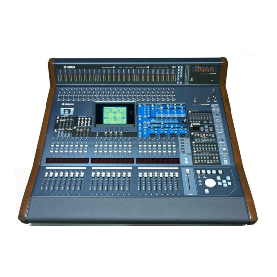
Page 18: Control Surface & Rear Panel
Chapter 2—Control Surface & Rear Panel 2 Control Surface & Rear Panel Control Surface DM2000—Owner’s Manual... - Page 19 Control Surface AD Input Section AD Input #1 is shown here. +48V ON/OFF switches These switches turn on and off the +48 V phantom power feed to each INPUT A (XLR-type connector). Phantom power is typically used to power condenser-type microphones or direct boxes.
- Page 20 Chapter 2—Control Surface & Rear Panel SOLO buttons These buttons are used to solo Channels. The [SOLO] button indicators of channels that are soloed light up. See “Soloing Channels” on page 118 for more information. ON buttons These buttons are used to mute Input and Output Channels. Their exact operation depends on the currently selected Layer.
- Page 21 Control Surface AUX SELECT AUX SELECT DISPLAY AUX SELECT DISPLAY button This button is used to select the following pages: Aux Send, Aux Send Pan, and Input Chan- nel Aux View. See “Aux Sends” on page 88 for more information. AUX 1–12 buttons These buttons are used to select Aux Sends when sending Input Channel signals to Aux Sends.
- Page 22 Chapter 2—Control Surface & Rear Panel FADER MODE FADER MODE FADER AUX/ MTRX FADER button This button selects Fader mode, in which the faders control Input or Output Channel levels, depending on the currently selected Layer. Its indicator lights up when this mode is selected. See “Selecting Fader Modes”...
- Page 23 Control Surface METER button This button is used to select the following pages: Input Channel Meter, Master Meter, Effect Input/Output Meter, Effect 1-2 Input/Output Meter, Effect 1–8 Input/Output Meter, Stereo Meter, and Metering Position. See “Metering” on page 103 for more information. VIEW button This button is used to select the following pages: Parameter View, Fader View, and Channel Library.
- Page 24 Chapter 2—Control Surface & Rear Panel PLUG-INS button This button is used to select the Plug-Ins in conjunction with the EFFECTS/PLUG-INS [1–8] buttons. Its indicator lights up when it’s pressed. See “Editing Plug-Ins” on page 153 for more information. CHANNEL INSERTS button If an internal effects processor or Y56K card effects chain is inserted in the currently selected channel, the relevant Effects Edit or Plug-In Edit page appears when this button is pressed, and its indicator lights up.
-
Page 25: Display Section
Control Surface Display Section Display This 320 x 240 dot display with fluorescent backlight displays pages, information on the currently selected Scene and channel, the sampling rate, and more. See “About the Display” on page 35 for more information. Contrast control This control is used to adjust the contrast of the display. - Page 26 Chapter 2—Control Surface & Rear Panel SELECTED CHANNEL Section SELECTED CHANNEL ROUTING PHASE / INSERT DELAY DISPLAY DISPLAY DISPLAY INSERT ON TIME AUX / MATRIX SEND DISPLAY LEVEL LEVEL LEVEL LEVEL BANK / MATRIX / MATRIX / MATRIX / MATRIX FOLLOW PAN STEREO DIRECT...
- Page 27 Control Surface ROUTING 1–8 buttons These buttons are used to route the currently selected Input Channel to the Bus Outs. The button indicators of Bus Outs to which the Input Channel is routed light up. See “Routing Input Channels” on page 75 for more information. PHASE/INSERT PHASE / INSERT DISPLAY...
- Page 28 Chapter 2—Control Surface & Rear Panel AUX/MATRIX SEND AUX / MATRIX SEND DISPLAY LEVEL LEVEL LEVEL LEVEL BANK / MATRIX / MATRIX / MATRIX / MATRIX AUX/MATRIX SEND DISPLAY button The pages selected by this button depends on the type of channel currently selected. If it’s an Input Channel, it selects the Aux Send, Aux Send Pan, and Input Channel Aux View pages.
- Page 29 Control Surface GATE/COMP button This button is used to set the rotary controls for either Gate or Compressor operation. When an Output Channel is selected, Compressor is selected automatically and cannot be changed. See “Gating Input Channels” on page 69 and “Compressing Channels” on page 113 for more information.
- Page 30 Chapter 2—Control Surface & Rear Panel PAN control This rotary control is used to pan the currently selected Input Channel. When a Matrix Send or the Stereo Out is selected, it is used to set the balance. For Input Channels in Gang or Inverse Gang Pan mode, horizontally or vertically paired Input Channels are panned simultaneously.
- Page 31 Control Surface EQ ON button This button is used to turn the EQ of the currently selected channel on and off. Its indicator lights up when the EQ is on. See “Using EQ” on page 107 for more information. ATT control This control is used to attenuate the pre-EQ signal of the currently selected channel.
- Page 32 Chapter 2—Control Surface & Rear Panel LAYER LAYER 1 24 REMOTE 25 48 REMOTE REMOTE 49 72 REMOTE 73 96 MASTER 1–24, 25–48, 49–72 & 73–96 buttons These buttons select the Input Channel Layers, which determine which Input Channels are controlled by the channel strips.
- Page 33 Control Surface TRACK ARMING TRACK ARMING DISPLAY ALL CLEAR MASTER TRACK ARMING GROUP TRACK ARMING DISPLAY button This button is used to select the following pages: Track Arming Group, MTR Track Arming Configuration, and Master Track Arming Configuration. See “Arming Machine Tracks” on page 225 for more information.
- Page 34 Chapter 2—Control Surface & Rear Panel STORE button This button is used to store the current Scene to the selected Scene memory. See “Storing & Recalling Scenes with the SCENE MEMORY Buttons” on page 159. Scene Up/Down buttons These buttons are used to select Scene memories. Pressing the Scene Up [ ] button incre- ments the selection;...
- Page 35 Control Surface RELATIVE button This button is used to set the Automix Fader Edit mode. It works in unison with the FADER EDIT buttons on the Automix Main page. See “FADER EDIT” on page 167 for more infor- mation. TOUCH SENSE button This button is used to turn on and off Fader Touch Sense for Automix recording.
- Page 36 Chapter 2—Control Surface & Rear Panel PRE button Pressing this button transmits a Locate command to the target machine (DAW, MMC or P2) in order to locate the Pre-Roll point. Its indicator lights up momentarily when it’s pressed. The Pre-Roll point is a predefined number of seconds before the specified In point. See “Using the Locator”...
- Page 37 Control Surface ROLL BACK button This button is used to roll back (i.e., rewind) the target machine (MMC or P2) from the cur- rent position by a predefined amount. Its indicator lights up momentarily when it’s pressed. See “Using the Locator” on page 222 for more information. REHEARSAL button This button is used to turn on and off the Rehearsal function on the target machine (MMC or P2).
- Page 38 Chapter 2—Control Surface & Rear Panel SHUTTLE button This button is used to set the Parameter wheel to Shuttle mode for machine control (DAW, MMC or P2). Its indicator lights up when Shuttle mode is on. See “Using Shuttle & Scrub” on page 222 for more information.
- Page 39 Control Surface Monitor, Phones & Talkback Section TALKBACK LEVEL PHONES SMALL STUDIO PHONES TRIM LEVEL LEVEL SMALL TRIM control This control is used to set the level of the SMALL CONTROL ROOM MONITOR OUT. See “Control Room Monitoring” on page 132 for more information. STUDIO LEVEL control This control is used to set the level of the STUDIO MONITOR OUT.
-
Page 40: Monitor Section
Chapter 2—Control Surface & Rear Panel MONITOR Section The various subsections of the MONITOR section are explained below. MONITOR DISPLAY STUDIO STUDIO CONTROL STEREO ROOM MONITOR DISPLAY STUDIO SOLO CONTROL STEREO ROOM SOLO CONTRAST CLEAR CONTROL ROOM MONITOR DISPLAY button STEREO This button is used to select the following pages: Solo Setting, Control Room Setup, and 2TR D1... - Page 41 Control Surface CONTROL ROOM CONTROL ROOM STEREO STEREO 2TR D1 button This button selects the 2TR IN DIGITAL AES/EBU 1 as the Control Room Monitor 2TR D1 2TR A1 signal source. Its indicator lights up when this source is selected. See “Control Room 2TR D2 2TR A2 Monitoring”...
- Page 42 Chapter 2—Control Surface & Rear Panel MONO button This button is used to switch the Control Room Monitor signal into mono. Its indicator lights up when mono is selected. See “Control Room Monitoring” on page 132 for more information. DIMMER button This button is used to dim the Control Room Monitor and Surround Monitor signals.
-
Page 43: Rear Panel
Rear Panel Rear Panel DM2000—Owner’s Manual... - Page 44 Chapter 2—Control Surface & Rear Panel AD Input Section INPUT A & B (BAL) connectors AD Inputs 1 through 24 feature balanced XLR-3-31-type connectors and balanced 1/4-inch phone jacks, both with a nominal input range of –60 dB to +10 dB. Phantom powering (+48 V) is supplied to the XLR-type connectors, with individual ON/OFF switches on each input.
- Page 45 Rear Panel STEREO OUT +4 dB (BAL) These balanced XLR-3-32-type connectors, nominal 2 (hot) Female XLR plug 3 (cold) output level +4 dB, output the analog Stereo Out signal and are typically connected the stereo inputs of a 1 (ground) 2-track recorder.
- Page 46 Chapter 2—Control Surface & Rear Panel Digital I/O & Control Section 7 8 9 KEYBOARD connector A PS/2 compatible keyboard can be connected here for quick entry of scene and library titles and channel names. See “Using a Keyboard” on page 38 for more information. SMPTE TIME CODE INPUT connector This balanced XLR-3-31-type connector is used to input SMPTE timecode for synchroniz- ing the Automix function.
- Page 47 228 for more information. REMOTE port This 9-pin D-sub connector can be used to connect an optional Yamaha AD824 AD Con- verter, providing remote and recallable control of its head amp settings. Machines that sup- port the Sony P2 protocol can also be controlled from the DM2000 via this port. A straight cable should be used to connect a P2 device;...
-
Page 48: Power Section
Chapter 2—Control Surface & Rear Panel Power Section POWER ON/OFF switch This switch is used to turn on the power to the DM2000. See “Turning On & Off the DM2000” on page 35 for more information. Grounding screw For electrical safety reasons, and correct operation of the touch-sensitive faders, it’s impor- tant that the DM2000 is grounded properly. -
Page 49: Operating Basics
Operating Basics 3 Operating Basics Connecting the Power Cord Warning: Turn off all equipment connected to the DM2000 before making any power connec- tions. Connect the socket-end of the supplied power cord to the AC IN on the rear panel of the DM2000. Connect the plug-end to a suit- able AC wall outlet, one that conforms to the power supply requirements stated on the DM2000’s rear panel. -
Page 50: Selecting Display Pages
Chapter 3—Operating Basics EDIT indicator: This indicator appears when the current mix settings no longer match those of the Scene that was recalled last. It works in unison with the Edit indicator dot on the SCENE MEMORY display. See “Edit Buffer & Edit Indicator” on page 157 for more information. -
Page 51: Display History
Display History When parameters are divided among several pages, for example, the Input Channel Atten- uators, which are divided among four pages, the page containing the parameter for the cur- rently selected channel is selected automatically when channels on different Layers are selected. -
Page 52: Title Edit Window
Chapter 3—Operating Basics Title Edit Window The Title Edit window is used to enter titles for Scene and library memories, automixes, and so on. Depending on the item being titled, the number of characters that can be entered is either 4, 12, or 16. The following screen shots show the available characters. The one on the left shows uppercase characters and various punctuation marks. -
Page 53: Channel Strip Displays
Channel Strip Displays Channel Strip Displays The fluorescent channel strip displays graphically display the value of the Input or Output Channel parameter currently assigned to the Encoders, routing settings, and the on/off status of the EQ, Insert, Delay, Comp, and Gate functions. They also display the Long and Short channel names C H 0 1 and indicate the currently selected channel. - Page 54 Chapter 3—Operating Basics Delay Feedback Gain, Delay Mix & EQ Gain Parameters 0%, ±0 dB Negative value Positive value ( indicates at 0%, ±0 dB) ( indicates 0%, ±0 dB) On/Off & Pre/Post Parameters EQ On/Off, Phase On/Off, Insert On/Off, EQ Type, Gate On/Off, Comp On/Off, Aux Send On/Off, Matrix Send On/Off, Aux Send Pre/Post, Matrix Send Pre/Post.
- Page 55 Channel Strip Displays Channel Names The channel strip displays also display the names or IDs of all the channels on the currently selected Layer. Each Input and Output Channel has a fixed Channel ID and Short and Long names that you can edit. See “Naming Channels” on page 130. You can choose whether the Short names or Channel IDs are displayed in the preferences.
-
Page 56: Selecting Layers
Chapter 3—Operating Basics Selecting Layers Input and Output Channels are arranged into Layers, as illustrated below. There are nine Layers altogether: four Input Channel Layers, one Master Layer (or Output Layer), and four Remote Layers. Input Channels [1–24] Input Channels [25–48] Input Channels [49–72] Input Channels [73–96] Bus Outs, Aux Sends, Matrix Sends [MASTER]... -
Page 57: Selecting Channels
Selecting Channels Selecting Channels To select Input and Output Channels for editing with the SELECTED CHANNEL controls, you use the LAYER buttons to select a Layer, and the [SEL] buttons to select a channel on that Layer. Select a Layer, as explained on page 42. Use the [SEL] buttons to select an Input or Output Channel. -
Page 58: Selecting Fader Modes
Chapter 3—Operating Basics Auto Channel Select & Touch Sense Select While the Auto Channel Select preference is on (see page 235), channels can be selected by moving the corresponding fader or Encoder, or by turning on the corresponding [AUTO], [SOLO], or [ON] button. While the Touch Sense Select preference is on (see page 237), channels can be selected sim- ply by touching the fader knobs. -
Page 59: Selecting Encoder Modes
Selecting Encoder Modes Selecting Encoder Modes The exact function of each Encoder depends on the selected Layer and Encoder mode. There are two preset Encoder modes, Pan and Aux/Mtrx, and four assign- able modes, for which you can choose from over 40 parameters. Select a Layer, as explained in page 42. -
Page 60: Assigning Parameters To The Encoder Mode Assign Buttons
Chapter 3—Operating Basics Assigning Parameters to the ENCODER MODE Assign Buttons Up to four parameters can be assigned to the four ENCODER MODE ASSIGN buttons. Initially, the following parameters are assigned to the ASSIGN buttons: [ASSIGN 1]: Input Patch [ASSIGN 2]: Direct Out [ASSIGN 3]: Surr. - Page 61 Assigning Parameters to the ENCODER MODE Assign Buttons Assignable Encoder Mode Parameter List Parameter Encoder Operation Push Switch Operation No Assign — — Attenuator Attenuator — Input Patch Input Channel patch Confirm patch selection Insert In Patch Insert In patch Confirm patch selection Insert Out Patch Insert Out patch...
-
Page 62: Analog I/O & The Ad Input Section
Chapter 4—wAnalog I/O & the AD Input Section 4 wAnalog I/O & the AD Input Section AD Input Section The DM2000 features 24 AD Inputs for connecting microphone and line-level sources. AD Inputs can be patched to Input Channels or Input Channel Insert Ins (see page 61). They can also be patched to Output Channel Insert Ins (see page 64). -
Page 63: Stereo Out
Stereo Out AD Inserts AD Inputs feature switchable analog inserts with individual balanced 1/4-inch TRS phone jacks for the send and return signals. They are wired: sleeve–ground, ring–cold, tip–hot. The nominal signal level for both connec- tors is +4 dB. AD Input inserts can be turned on and off individually by using the INSERT ON/OFF switches, so you don’t have to disconnect your external equipment in INSERT... -
Page 64: Digital I/O & Cascading
Chapter 5—Digital I/O & Cascading 5 Digital I/O & Cascading Wordclocks Unlike analog audio equipment, digital audio equipment must be synchronized when dig- ital audio signals are transferred from one device to another, otherwise, signals may not be received correctly and audible noise, glitches, or clicks may occur. Synchronization is achieved using what’s called a wordclock, which is a clock signal for synchronizing all the digital audio signals in a system. - Page 65 Wordclocks Selecting the Wordclock Source The wordclock source can be selected as follows. Note: When you change the wordclock settings on any device in your digital audio system, some devices may output noise, so turn down your power amps beforehand, otherwise your speakers may be damaged.
-
Page 66: 2Tr Digital Outs
Chapter 5—Digital I/O & Cascading Terminating External Wordclocks Wordclock signals distributed via BNC cables must be terminated correctly, otherwise, jitter and synchronization errors may result. Ideally, you should make a separate wordclock con- nection to each device and terminate it. The following examples show two ways in which wordclock signals can be distributed and how termination should be applied in each case. -
Page 67: 2Tr Digital Ins
2TR Digital Ins 2TR Digital Ins The DM2000 features three sets of 2-track digital inputs: 2TR IN DIGITAL AES/EBU 1 and AES/EBU 2 use XLR-3-31-type connec- tors and accept AES/EBU format digital audio. 2TR IN DIGITAL COAXIAL 3 uses a phono connector and accepts consumer format (IEC-60958) digital audio. -
Page 68: Slot I/O
Chapter 5—Digital I/O & Cascading Slot I/O The DM2000 features six Slots for installing optional mini-YGDAI (Yamaha General Digi- tal Audio Interface) I/O Cards, which offer various analog I/O options and digital I/O inter- faces in all the popular digital audio interconnect formats, including AES/EBU, ADAT, and Tascam. - Page 69 Slot I/O Installing I/O Cards Attention: For technical reasons, certain card combinations are not supported. Before installing any cards, check the Yamaha web site (see page 6) to see whether your card is compatible. http://www.yamahaproaudio.com/ Also check the total number of cards that can be installed in the unit. Installing cards that are not endorsed by Yamaha may cause electrical shock, fire, or damage to the unit.
- Page 70 Chapter 5—Digital I/O & Cascading Setting the Transfer Format for Higher Sampling Rates The data transfer format for the higher sampling rates can be set as follows. Use the DISPLAY ACCESS [DIO] button to locate the Higher Sample Rate Data Transfer Format page.
-
Page 71: Dithering Digital Outputs
Dithering Digital Outputs Dithering Digital Outputs For digital audio transfer to lower-resolution systems, the 2TR Digital Outputs and Slot Outputs can be dithered to 16-bit, 20-bit, or 24-bit. Use the DISPLAY ACCESS [DIO] button to locate the Dither page. Use the cursor buttons to select the Dither parameters, and use the Param- eter wheel or INC/DEC buttons to set them. -
Page 72: Cascading Consoles
Up to four DM2000s can be cascaded, offering a maximum of 384 Input Channels. Several functions are linked between all cascaded consoles, including Solo, Scene Recall and Store, so that all consoles work just like one big console. A single Yamaha 02R Digital Recording Console can be included in the cascade system. - Page 73 Cascading Consoles Cascade Hookup Examples Cascading Two DM2000s Master: Off Master: On Bi-directional: - Bi-directional: On CASCADE OUT CASCADE IN DM2000 #1 DM2000 #2 CASCADE IN CASCADE OUT Final signals Final signals can be output by the can be output by the Slot Outputs or Omni Outs.
- Page 74 Chapter 5—Digital I/O & Cascading Attenuating Cascade Inputs Cascade Inputs can be attenuated, and the Cascade mode and Cascade source can be spec- ified on the Cascade In page. Use the DISPLAY ACCESS [DIO] button to locate the Cascade In page. Use the cursor buttons to select the parameters, and use the Parameter wheel, INC/DEC buttons, or [ENTER] button to set them.
-
Page 75: Input & Output Patching
Input & Output Patching 6 Input & Output Patching Input Patching Signal sources for the Input Channels, Input Channel Insert Ins, and internal effects pro- cessors are selected on the Input Patch pages, which are selected by using the DISPLAY ACCESS [INPUT PATCH] button. - Page 76 Chapter 6—Input & Output Patching Patching Input Channel Insert Ins AD Inputs, Slot Inputs, internal effects processor outputs, Digital or Analog 2TR Inputs can be patched to the Input Channel Insert Ins. The Input Channel Insert In Patch parameters for the 96 Input Channels are divided between two pages.
-
Page 77: Output Patching
Output Patching Output Patching Signal sources for the Slot Outputs, Omni Outs, Output Channel Inserts Ins, Direct Outs, 2TR Digital Outputs, and GEQs are selected on the Output Patch pages, which are selected by using the DISPLAY ACCESS [OUTPUT PATCH] button. Use the cursor buttons to select the patch parameters, use the Parameter wheel or INC/DEC buttons to select a source, and press [ENTER] to set. - Page 78 Chapter 6—Input & Output Patching Patching Omni Outs Bus Outs, Aux Sends, Matrix Sends, the Stereo Out, Input or Output Channel Insert Outs, or Surround Monitor Channels can be patched to the Omni Outs. Omni Outs can be patched to Direct Outs on the Direct Out Destination pages (see page 65). When an Omni Out is patched to a Direct out (see page 65), and that Direct Out is assigned on an Input Channel Routing page, the Omni Out patch cannot be changed here.
- Page 79 Output Patching Patching Direct Outs Direct Outs can be patched to the Slot Outputs, Omni Outs, or 2TR Digital Outputs. The Direct Out Destination parameters for the 96 Input Channels are divided between two pages. The Input Channel 1–48 Direct Out Destination page is shown below. The layout of the other page is the same.
-
Page 80: Naming Input & Output Ports
Chapter 6—Input & Output Patching Patching the GEQs The six 31-band graphic equalizers can be inserted into the Bus Outs, Aux Sends, or the left or right channels of the Matrix Sends or Stereo Out on the Graphic Equalizer Insert page. GEQs can also be patched on the Graphic Equalizer Edit page (see page 155) or the Output Channel Insert page (see page 111). -
Page 81: Patch Select Window
Patch Select Window Patch Select Window Input and Output patches can be made by using the Patch Select window, shown below, which appears when the [ENTER] button is pressed while a patch parameter is selected. Available input and output sources and destinations are displayed in a hierarchical format in three panes. -
Page 82: Input Channels
Chapter 7—Input Channels 7 Input Channels Patching Input Channels AD Inputs, Slot Inputs, internal effects processor outputs, Digital or Analog 2TR Inputs, Bus Outs, or Aux Sends can be patched to the Input Channel Inputs. See “Patching Input Channels” on page 61 for more information. Metering Input Channels Input Channel signal levels can be metered on the Meter pages. -
Page 83: Gating Input Channels
Gating Input Channels Gating Input Channels Each Input Channel features a noise Gate for automatically shutting out unwanted noise. Gate settings can be stored in the Gate library, which contains 4 preset memories and 88 user memories. See “Gate Library” on page 144 for more information. Preset Gates &... -
Page 84: Attenuating Input Channels
Chapter 7—Input Channels Use the SELECTED CHANNEL DYNAMICS [DISPLAY] button to locate the Gate Edit page. Use the cursor buttons to select the parameters, and use the Parameter wheel, INC/DEC buttons, and [ENTER] button to set them. KEYIN SOURCE: This determines the trigger source for the currently selected Input Channel’s Gate. -
Page 85: Grouping Input Channel Eqs
Grouping Input Channel EQs Grouping Input Channel EQs Input Channel EQs can be grouped, allowing you to control the EQ of several Input Chan- nels simultaneously. There are four Input Channel EQ groups: a, b, c, and d. Use the DISPLAY ACCESS [GROUP] button to locate the Input Equalizer Link page. -
Page 86: Grouping Input Channel Compressors
Chapter 7—Input Channels Grouping Input Channel Compressors Input Channel Compressors can be grouped, allowing you to control the compression of several Input Channels simultaneously by operating any Compressor control in the group. There are four Input Channel Compressor groups: i, j, k, and l. Use the DISPLAY ACCESS [GROUP] button to locate the Input Comp Link page. -
Page 87: Grouping Input Channel Mutes (On/Off)
Grouping Input Channel Mutes (ON/OFF) Grouping Input Channel Mutes (ON/OFF) Input Channel Mutes can be grouped, allowing you to mute several Input Channels simul- taneously. There are eight Input Channel Mute groups: I, J, K, L, M, N, O, and P. Use the DISPLAY ACCESS [GROUP] button to locate the Input Channel Mute Group pages. -
Page 88: Setting Input Channel Levels
Chapter 7—Input Channels Setting Input Channel Levels Input Channel levels can be set as follows. Use the LAYER buttons to select the Input Channel Layers. Press the FADER MODE [FADER] button to select Fader mode. Use the faders to set the Input Channel levels. Refer to the legend on the left side of the faders when setting Input Channel levels. -
Page 89: Routing Input Channels
Routing Input Channels Routing Input Channels Each Input Channel can be routed to the Bus Outs, Stereo Out, or its own Direct Out. Using the SELECTED CHANNEL ROUTING Controls Use the LAYER buttons to select the Input Channel Layers, ROUTING and use the [SEL] buttons to select the Input Channels. -
Page 90: Panning Input Channels
Chapter 7—Input Channels The currently selected Surround mode is displayed in the lower-left corner. When Stereo mode is selected, the Bus Out routing buttons display numbers from 1 through 8. When a Surround Pan mode is selected, they display abbreviations of the Surround Channel names, as shown in the following table. -
Page 91: Using Surround Pan
Using Surround Pan The Pan parameters for the 96 Input Channels are arranged into four pages. The Input Channel 1–24 Pan page is shown below. The layout of the other three pages is the same. Use the cursor buttons to select the Pan controls, and use the Parameter wheel and INC/DEC buttons to set them. - Page 92 Chapter 7—Input Channels Selecting Surround Pan Modes The Surround mode can be selected as follows. Use the SELECTED CHANNEL PAN/SURROUND [DISPLAY] button to select the Surround Mode page. Use the cursor buttons to select the surround mode buttons, and press [ENTER] to activate the selected mode.
- Page 93 Using Surround Pan Selected Channel Surround Edit Page Surround pan settings can be viewed and set on the Input Channel Surround Edit page. If the Auto PAN/SURROUND Display preference is on, and a Surround Pan mode other than Stereo is selected, this page appears automatically when a PAN/SURROUND control other than the [EFFECT] button is operated.
-
Page 94: Sending Input Channels To Aux Sends
Chapter 7—Input Channels DEPTH OFFSET: This can be used to offset the front-to-rear direction of the selected pat- tern. ST LINK: This can be used to link the surround pan parameters of the currently selected Input Channel and its horizontal or vertical partner regardless of whether they are paired. PATTERN: When Input Channels are linked, the seven patterns selectable here determine how the linked surround pan moves by the Parameter wheel and INC/DEC buttons. -
Page 95: Soloing Input Channels
Soloing Input Channels Soloing Input Channels Input Channels can be soloed. See page 118 for more information. Direct Outs Each Input Channel features a Direct Out, which can be patched to the Slot Outputs, Omni Outs, or the 2TR Digital Outputs. Direct Out signals can be sourced pre-EQ, pre-fader, or post-fader. -
Page 96: Stereo Out
Chapter 8—Stereo Out 8 Stereo Out Stereo Out Connectors The Stereo Out is output by the STEREO OUT +4 dB (BAL) balanced XLR-3-32-type connectors and the STEREO OUT –10 dBV (UNBAL) unbalanced phono connectors. Patching the Stereo Out to Outputs The left and right channels of the Stereo Out can be patched to the Slot Outputs, Omni Outs, or the 2TR Digital Outputs. -
Page 97: Compressing The Stereo Out
Compressing the Stereo Out Compressing the Stereo Out Signal dynamics can be controlled by using the Stereo Out Compressor. See “Compressing Channels” on page 113 for more information. Grouping Master Compressors The Stereo Out Compressor can be grouped with the Compressors of other Output Chan- nels. -
Page 98: Balancing The Stereo Out
Chapter 8—Stereo Out Balancing the Stereo Out The left and right channels of the Stereo Out can be balanced as follows. Press the STEREO [SEL] button to select the Stereo Out. PAN / SURROUND DISPLAY EVEN Use the Pan control to set the balance. The pan display indicates the balance. -
Page 99: Bus Outs
Bus Outs 9 Bus Outs Patching Bus Outs to Outputs Bus Outs can be patched to the Slot Outputs, Omni Outs, or the 2TR Digital Outputs. See “Output Patching” on page 63 for more information. Routing Input Channels to Bus Outs Input Channels can be routed to the Bus Outs. -
Page 100: Muting Bus Outs (On/Off)
Chapter 9—Bus Outs Muting Bus Outs (ON/OFF) Bus Outs can be muted by using the channel strip [ON] buttons. Press the LAYER [MASTER] button to select the Master Layer. Use channel strip [ON] buttons 1–8 to mute the Bus Outs. The [ON] button indicators of Bus Outs that are on light up. -
Page 101: Sending Bus Outs To The Stereo Out
Sending Bus Outs to the Stereo Out Sending Bus Outs to the Stereo Out Bus Outs can be routed to the Stereo Out buses as follows. Bus Out to Stereo Out settings can be stored in the Bus to Stereo library, which contains 1 preset memory and 32 user memories. -
Page 102: 10 Aux Sends
Chapter 10—Aux Sends 10 Aux Sends Patching Aux Send Masters to Outputs Aux Send Masters can be patched to the Slot Outputs, Omni Outs, or the 2TR Digital Out- puts. See “Output Patching” on page 63 for more information. Setting the Aux Send Mode Aux Sends have two operating modes—Variable and Fixed—which can be set individually for each of the 12 Aux Sends. -
Page 103: Setting Aux Send Levels
Setting Aux Send Levels Setting Aux Send Levels Aux Send levels can be set by using the SELECTED CHANNEL AUX/MATRIX SEND LEVEL controls, the faders, or the Encoders. Using the SELECTED CHANNEL AUX/MATRIX SEND LEVEL Controls Use the LAYER buttons to select the Input Channel Layers, and use the [SEL] buttons to select Input Channels. -
Page 104: Muting Aux Sends (On/Off)
Chapter 10—Aux Sends Muting Aux Sends (ON/OFF) Use the LAYER buttons to select the Input Channel Layers, and use the [SEL] buttons to select the Input Channels. Use the SELECTED CHANNEL AUX/MATRIX SEND [BANK] button to select Aux 1–4, Aux 5–8, or Aux 9–12. Use the SELECTED CHANNEL AUX/MATRIX SEND [ON] buttons to turn the Aux Sends of the selected Input Channel on or off. - Page 105 Aux Send Pages To set Aux Send levels, select the rotary controls, and use the Parameter wheel or INC/DEC buttons. To set the Pre/Post parameters, select the PRE/POST buttons, and use the [ENTER] button or INC/DEC buttons. To set all Input Channels for the selected Aux Send to pre-fader or post-fader simultaneously, select the GLOBAL PRE or POST button, and then press [ENTER].
-
Page 106: Viewing Aux Send Settings
Chapter 10—Aux Sends Viewing Aux Send Settings You can view and set settings of all Aux Sends on the Aux View pages. Level and Pre/Post parameters are displayed separately. If the Auto AUX/MATRIX Display preference is on, and an Input Channel is currently selected, these pages appear automatically when a SELECTED CHANNEL AUX/MATRIX SEND control is operated. - Page 107 Viewing Aux Send Settings Pre/Post Parameters In Pre/Post mode, the Aux View pages display Aux Send Pre/Post parameters. Fixed mode Aux Sends can be turned on and off only. Use the AUX SELECT [DISPLAY] button to select the Aux View pages. Select the DISPLAY PRE/POST button, and press [ENTER].
-
Page 108: Panning Aux Sends
Chapter 10—Aux Sends Panning Aux Sends When Aux Sends are paired, Aux Sends can be panned between the paired Aux buses. See “Pairing Channels” on page 120 for more information. If the selected Aux Send is not paired, the message “AUXx–x are not paired” appears. If the currently selected pair of Aux Send Masters is set to Follow Surround on the Output Pair page, Aux Sends follow the Input Channel Surround Pan settings and cannot be set here, in which case the message “Now AUXx-x PAN Following Surround”... -
Page 109: Metering Aux Send Masters
Metering Aux Send Masters Metering Aux Send Masters Aux Send Master levels can be metered on the Meter pages. See “Metering” on page 103 for more information. Monitoring Aux Send Masters Aux Send Masters can be assigned to the CONTROL ROOM [ASSIGN 1] or [ASSIGN 2] button for monitoring. -
Page 110: Settings Aux Send Master Levels
Chapter 10—Aux Sends Settings Aux Send Master Levels Aux Send Master levels can be set as follows. Press the LAYER [MASTER] button to select the Master Layer. Press the FADER MODE [FADER] button to select the Fader mode. Use faders 9–20 to set the Aux Send Master levels. Refer to the legend on the right side of the faders when setting Aux Send Master levels. -
Page 111: 11 Matrix Sends
Matrix Sends 11 Matrix Sends Patching Matrix Send Masters to Outputs The left and right channels of the Matrix Send Masters can be patched to the Slot Outputs, Omni Outs, or the 2TR Digital Outputs. See “Output Patching” on page 63 for more infor- mation. -
Page 112: Muting Matrix Sends (On/Off)
Chapter 11—Matrix Sends Use the MATRIX SELECT [1–4] buttons to select Matrix Sends 1–4. Use Encoders 1–20 to set the Matrix Send levels. Encoders 21–24 are inactive because Matrix Send Masters do not feature Matrix Send controls. Muting Matrix Sends (ON/OFF) Press the LAYER [MASTER] button to select the Master Layer. -
Page 113: Panning Matrix Sends
Panning Matrix Sends Panning Matrix Sends Matrix Sends can be panned on the Matrix Send Pan page. The Matrix Sends for the left and right channels of the Stereo Out can be panned individually. Use the MATRIX SELECT [DISPLAY] button to select the Matrix Send Pan page. -
Page 114: Metering Matrix Send Masters
Chapter 11—Matrix Sends If the Master Layer is currently selected, [SEL] buttons 1–20 can also be used to select Out- put Channels. Matrix Sends can also be selected by using the MATRIX SELECT [1–4] but- tons. Use the Parameter wheel or INC/DEC buttons to set the levels of the Matrix Sends. -
Page 115: Grouping Master Compressors
Grouping Master Compressors Grouping Master Compressors Matrix Send Master Compressors can be grouped with the Compressors of other Output Channels. See “Grouping Output Channel Compressors” on page 116 for more informa- tion. Muting Matrix Send Masters (ON/OFF) Matrix Send Masters can be muted as follows. Press the LAYER [MASTER] button to select the Master Layer. -
Page 116: Delaying Matrix Send Masters
Chapter 11—Matrix Sends Delaying Matrix Send Masters Each Matrix Send Master features a Delay function. See “Delaying Channel Signals” on page 117 for more information. Soloing Matrix Sends Matrix Sends can be soloed. See page 118 for more information. Inserting GEQs Internal GEQs can be inserted into the left and right channels of the Matrix Send Masters. -
Page 117: 12 Common Channel Functions
Common Channel Functions 12 Common Channel Functions Metering Input Channels, Bus Outs, Aux Sends, Matrix Sends, the Stereo Out, and the Effects proces- sors can be metered on the various Meter pages, which are located by using the DISPLAY ACCESS [METER] button. Input and Output Channel Meter pages also display fader positions numerically. - Page 118 Chapter 12—Common Channel Functions There are two 48-channel Meter pages. The Input Channel 1–48 Meter page is shown below. The layout of the other page is the same. Metering Output Channels Bus Outs, Aux Sends, Matrix Sends, and the Stereo Out can all be metered on the Master Meter page.
- Page 119 Metering The Effects 1–2 Input/Output Meter page features individual level meters for the eight inputs and outputs of internal effects processors #1 and #2. Metering the Stereo out The Stereo Out can be metered on the Stereo Meter page. Peak signal levels for the left and right channels are displayed numerically.
-
Page 120: Attenuating Signals
Chapter 12—Common Channel Functions Attenuating Signals Input Channels, Bus Outs, Aux Sends, Matrix Sends, and the Stereo Out all feature pre-EQ attenuation, which is useful for attenuating “hot” signals before EQ’ing. Using the SELECTED CHANNEL EQUALIZER ATT Control Use the LAYER buttons to select Layers, and use the [SEL] buttons to select channels. -
Page 121: Using Eq
Using EQ Using EQ Input Channels, Bus Outs, Aux Sends, Matrix Sends, and the Stereo Out all feature 4-band parametric EQ. The LOW-MID and HIGH-MID bands are peaking type. The LOW and HIGH bands can be set to shelving, peaking, or HPF and LPF respectively. EQ settings can be stored in the EQ library, which contains 40 preset memories and 160 user memories. - Page 122 Chapter 12—Common Channel Functions Preset Name Description 33 Bass Drum 3 A variation on preset 1, with low and mid range reduced. 34 Snare Drum 3 A variation on preset 3, creating a thicker sound. 35 Tom-tom 2 A variation on preset 5, emphasizing the mid and high ranges. 36 Piano 3 A variation on preset 13.
- Page 123 EQ ON: This turns the EQ on and off. The [ENTER] button can be used to turn this on and off so long as any parameter other than TYPE is selected. TYPE: This selects the type of EQ: TYPE I (the EQ type used on legacy Yamaha digital mix- ing consoles) or TYPE II (a newly developed algorithm).
-
Page 124: Grouping Output Channel Eqs
Chapter 12—Common Channel Functions Grouping Output Channel EQs The Bus Out, Aux Send, Matrix Send, and Stereo Out EQs can be grouped, allowing you to control the EQ of several Output Channels simultaneously. There are four Output Channel EQ groups: e, f, g, and h. Use the DISPLAY ACCESS [GROUP] button to locate the Output Equalizer Link page. -
Page 125: Using Inserts
Using Inserts Using Inserts Input Channels, Bus Outs, Aux Sends, Matrix Sends, and the Stereo Out all feature assign- able Inserts. Using the SELECTED CHANNEL PHASE/INSERT [INSERT ON] Button Use the LAYER buttons to select Layers, and use the [SEL] buttons to select channels. - Page 126 Chapter 12—Common Channel Functions Use the LAYER buttons to select Layers, and use the [SEL] buttons to select channels. Use the cursor buttons to select the parameters, and use the Parameter wheel, INC/DEC buttons, and [ENTER] button to set them. INSERT ON/OFF: This turns the currently selected channel’s Insert on and off.
-
Page 127: Compressing Channels
Compressing Channels Compressing Channels Input Channels, Bus Outs, Aux Sends, Matrix Sends, and the Stereo Out all feature a Com- pressor. Settings can be stored in the Comp library, which contains 36 preset memories and 88 user memories. See “Comp Library” on page 145 for more information. Preset Comps &... - Page 128 Chapter 12—Common Channel Functions Preset Name Type Description A variation on preset 26, intended for sampled loops and 27 Hip Comp COMPAND-S phrases. 28 Solo Vocal1 COMP Compressor for use with main vocals. 29 Solo Vocal2 COMP A variation on preset 28. 30 Chorus COMP A variation on preset 28, intended for choruses.
- Page 129 Compressing Channels Use the SELECTED CHANNEL DYNAMICS [DISPLAY] button to locate the Comp Edit page. Use the cursor buttons to select the parameters, and use the Parameter wheel, INC/DEC buttons, and [ENTER] button to set them. POSITION: This determines the position of the Compressor within the channel, and can be set to pre-EQ, pre-fader, or post-fader.
-
Page 130: Grouping Output Channel Compressors
Chapter 12—Common Channel Functions Grouping Output Channel Compressors The Bus Out, Aux Send, Matrix Send, and Stereo Out Compressors can be grouped, allow- ing you to control the compression of several Output Channels simultaneously. There are four Output Channel Compressor groups: m, n, o, and p. Use the DISPLAY ACCESS [GROUP] button to locate the Output Comp Link page. -
Page 131: Delaying Channel Signals
Delaying Channel Signals Delaying Channel Signals Input Channels, Bus Outs, Aux Sends, Matrix Sends, and the Stereo Out all feature inde- pendent Delay functions. Input Channel Delays feature feedback, with independent Mix and Gain parameters. Using the SELECTED CHANNEL DELAY Controls Use the LAYER buttons to select Layers, and use DELAY the [SEL] buttons to select channels. -
Page 132: Soloing Channels
Chapter 12—Common Channel Functions The Delay parameters for the Bus Outs, Aux Sends, Matrix Sends, and the Stereo Out appear on the Output Delay page. Use the cursor buttons to select the Delay parameters, and use the Parameter wheel, INC/DEC buttons, and [ENTER] button to set them. Input and Output Channels can also be selected by using the LAYER and [SEL] buttons. - Page 133 Soloing Channels Configuring Solo The Solo function is configured on the Solo Setup page. If the Auto SOLO Display prefer- ence is on, this page appears automatically when a channel is soloed. See “Auto SOLO Dis- play” on page 234. Use the MONITOR [DISPLAY] button to locate the Solo Setup page.
-
Page 134: Pairing Channels
Chapter 12—Common Channel Functions Pairing Channels Input Channels, Bus Outs, and Aux Sends can be paired for stereo operation. Input Chan- nels can be paired either horizontally, that is, adjacent odd-even channels on the same Layer (e.g., 1-2, 3-4, 5-6, etc) or vertically, that is, counterpart channels on adjacent Layers (e.g., 1-25, 2-26, 49-73, 50-74, etc). - Page 135 Pairing Channels To set the pair mode, select the PAIR MODE HORIZONTAL or VERTICAL but- tons, and press [ENTER]. The Pair mode can be set independently for Input Channels 1–48 and Input Channels 49–96. The Input Channel 1–48 Pair page in Vertical mode is shown below. Pair parameters for the Bus Outs and Aux Sends appear on the Output Pair page.
-
Page 136: Grouping Output Channel Faders
Chapter 12—Common Channel Functions When a Surround mode other than Stereo is selected, Aux Sends can be set to follow the same Input Channel Surround Pan that applies to the Bus Outs, which is useful for feeding Surround channel signals to external effects processors. This is turned on and off by using the F.S buttons that appear below the Aux Send Pair buttons. -
Page 137: Grouping Output Channel Mutes (On/Off)
Grouping Output Channel Mutes (ON/OFF) Grouping Output Channel Mutes (ON/OFF) The Bus Out, Aux Send, Matrix Send, and Stereo Out mutes can be grouped, allowing you to mute several Output Channels simultaneously. There are four Output Channel Mute groups: U, V, W, and X. Use the DISPLAY ACCESS [GROUP] button to locate the Output Mute Group page. -
Page 138: Viewing Channel Parameter Settings
Chapter 12—Common Channel Functions Viewing Channel Parameter Settings The parameter setting of the currently selected Input Channel, Bus Out, Aux Send, Matrix Send, or the Stereo Out can be viewed and set on the Parameter View pages. Use the DISPLAY ACCESS [VIEW] button to select the Parameter View page. Use the LAYER buttons to select Layers, and use the [SEL] buttons to select channels. -
Page 139: Viewing Channel Fader Settings
Viewing Channel Fader Settings Output Channels This is the Parameter View page for the Bus Outs, Aux Sends, Matrix Sends, and the Stereo Out. Parameters are the same as for the Input Channel Parameter View page, minus the GATE and Phase sections and the DELAY MIX and FB GAIN parameters. The parameter settings of the left and right channels of the Matrix Sends and Stereo Out can be viewed individually. - Page 140 Chapter 12—Common Channel Functions numerically below the fader. See “Setting Input Channel Levels” on page 74 for more infor- mation. SURROUND PAN: The Surround pan parameters for the currently selected Input Chan- nel are displayed only when a Surround mode other than Stereo is selected. See “Using Sur- round Pan”...
- Page 141 Viewing Channel Fader Settings Aux Sends Below is the Fader View page for the Aux Sends. ON/OFF: This is the On/Off parameter of the currently selected Aux Send. See “Muting Aux Sends (ON/OFF)” on page 90 for more information. Fader: This indicates the fader position of the currently selected Aux Send. The fader knob appears highlighted when the fader is set to 0.0 dB.
- Page 142 Chapter 12—Common Channel Functions Fader: This indicates the fader position of the currently selected Matrix Send. The fader knob appears highlighted when the fader is set to 0.0 dB. The fader position is displayed numerically below the fader. See “Setting Matrix Send Master Levels” on page 101 for more information.
-
Page 143: Copying Channel Settings
Copying Channel Settings Copying Channel Settings The settings of Input Channels, Bus Outs, Aux Sends, Matrix Sends, and the Stereo CHANNEL Out can be copied among channels of the same type by using the Channel Copy function. You can even copy to and from channels in Scenes without recalling COPY them. -
Page 144: Naming Channels
Chapter 12—Common Channel Functions Copying Channel Settings Between Noncurrent Scenes Use the SCENE MEMORY Up [ ] and Down [ ] buttons to select the source Scene. The number of the source Scene flashes on the SCENE MEMORY display. Use the LAYER and [SEL] buttons to select the source channel. Press the CHANNEL [COPY] button. - Page 145 Naming Channels Output Channels Use the DISPLAY ACCESS [OUTPUT PATCH] button to locate the Output Channel Name page Use the Parameter wheel, INC/DEC buttons, or the Master Layer and [SEL] buttons to select the Output Channels. Use the cursor buttons to select the Output Channel’s Long or Short name, and then press [ENTER].
-
Page 146: 13 Monitoring & Talkback
Chapter 13—Monitoring & Talkback 13 Monitoring & Talkback Control Room Monitoring The DM2000 features independent outputs and level controls for two sets of studio monitors. The LARGE CONTROL ROOM MONITOR OUT +4 dB (BAL) XLR-3-32-type connectors are intended to feed to the control room’s main monitors. -
Page 147: Studio Monitoring
Studio Monitoring Control Room Setup Control room monitoring is configured on the Control Room Setup page. Use the MONITOR [DISPLAY] button to locate the Control Room Setup page. Use the cursor buttons to select the ASSIGN buttons in the left-hand box, and use the Parameter wheel to select an Output Channel in the right-hand box. -
Page 148: Surround Monitoring
Chapter 13—Monitoring & Talkback Surround Monitoring The DM2000 features comprehensive surround monitoring functions, including a pink noise generator for speaker setup, Bass Management, and down mixing. The Surround pages explained in this section are available only when a Surround mode other than Stereo is selected (see page 78). - Page 149 Surround Monitoring When the MONITOR L/R to C-R button is on, the Left and Right Surround Monitor Chan- nels are fed to the Control Room Monitors. This is useful when you want to use the same speakers for Left and Right Surround Monitors and Control Room Monitors. STATUS: SURROUND MODE indicates the currently selected Surround mode, which is set on the Surround Mode page (see page 78).
- Page 150 Chapter 13—Monitoring & Talkback MONITOR MATRIX: This is used to select the Surround Monitor Matrix. In 5.1 Sur- round mode, you can select 5.1, 3-1, or ST. In 3-1 Surround mode, you can select 3-1 or ST. When a down mix Monitor Matrix is selected, you can attenuate signals by using the ATT parameters.
- Page 151 Surround Monitoring MONITOR ALIGNMENT ATT & DLY ON/OFF: These buttons are used to turn on and off the Monitor Alignment Attenuator and Delay parameters of all Sur- round speakers. The MONITOR ALIGNMENT diagram and Surround Channel Attenuator and Delay parameters, which are displayed when either of these buttons are selected, allow you to align the surround monitor speak- ers by attenuating and delaying Surround Channels as...
-
Page 152: Using Talkback & Slate
Chapter 13—Monitoring & Talkback Using Talkback & Slate The Talkback function distributes the Talkback mic signal to the Studio Monitor Outs and any Slot or Omni Outputs specified on the Talkback Setup page. The TALKBACK LEVEL control sets the level of the built-in talkback micro- phone. -
Page 153: 14 Libraries
Libraries 14 Libraries About the Libraries The DM2000 features 11 libraries for storing Automix, Effects, Channel, Input Patch, Out- put Patch, GEQ, Bus to Stereo, Gate, Comp, EQ, and Surround Monitor data. Library data can be stored to an external MIDI device, such as a MIDI data filer, by using MIDI Bulk Dump (see page 187). -
Page 154: Channel Library
Chapter 14—Libraries Memory #U is a special read-only memory that allows you to undo and redo memory recall and store operations. After recalling a memory, you can revert to the previously recalled memory by recalling memory #U. After storing a memory, you can revert it to its previous contents by recalling memory #U. -
Page 155: Input Patch Library
Input Patch Library Input Patch Library Input Patch settings can be stored in the Input Patch library, which contains 1 preset mem- ory and 32 user memories. See page 61 for information on Input Patch settings. Use the DISPLAY ACCESS [INPUT PATCH] button to select the Input Patch Library page. -
Page 156: Geq Library
Chapter 14—Libraries GEQ Library GEQ settings can be stored in the GEQ library, which contains 1 preset memory and 128 user memories. See page 155 for information on using the GEQs. Use the EFFECTS/PLUG-INS [DISPLAY] button to select the Graphic Equalizer Library page. -
Page 157: Bus To Stereo Library
Bus to Stereo Library TYPE: This is the effects type used in the previously recalled Effects memory. Its I/O con- figuration is shown below this. Level meters: These meters indicate the output levels of the currently selected Effects processor. There are eight output meters for Effects processors #1 and #2, and two output meters for Effects processors #3 through #8. -
Page 158: Gate Library
Chapter 14—Libraries Gate Library Input Channel Gate settings can be stored in the Gate library, which contains 4 preset mem- ories and 124 user memories. See page 69 for information on gating Input Channels. Use the DYNAMICS [DISPLAY] button to select the Gate Library page. Use the LAYER buttons to select the Input Channel Layers, and the [SEL] but- tons to select Input Channels. -
Page 159: Comp Library
Comp Library Comp Library Comp settings can be stored in the Comp library, which contains 36 preset memories and 92 user memories. See page 113 for information on the Comps. Use the DYNAMICS [DISPLAY] button to select the Comp Library page. Use the LAYER buttons to select Layers, and the [SEL] buttons to select chan- nels. -
Page 160: Eq Library
Chapter 14—Libraries EQ Library Input Channel, Bus Out, Aux Send, Matrix Send, and Stereo Out EQ settings can be stored in the EQ library, which contains 40 preset memories and 160 user memories. See page 107 for information on EQ’ing. Use the EQUALIZER [DISPLAY] button to select the EQ Library page. -
Page 161: Automix Library
Automix Library Automix Library Up to 16 Automixes can be stored in the Automix library. See page 164 for information on using Automix. Use the AUTOMIX [DISPLAY] button to select the Automix Memory page. When storing, the current Automix is stored to the selected memory. TITLE: This is the title of the current Automix. -
Page 162: 15 Internal Effects, Plug-Ins & Geqs
Chapter 15—Internal Effects, Plug-Ins & GEQs 15 Internal Effects, Plug-Ins & GEQs About the Effects The DM2000 features eight internal multi-effects processors, offering a whole host of effects types, including reverbs, delays, modulation-based effects, combination effects, and multi- channel effects designed especially for use with surround sound. Effects processors 3–8 feature assignable stereo inputs and outputs. - Page 163 Preset Name Type Description 13 Chorus CHORUS Chorus 14 Flange FLANGE Flanger Proprietary Yamaha effect that produces a richer and more 15 Symphonic SYMPHONIC complex modulation than normal chorus 16 Phaser PHASER 16-stage stereo phase shifter 17 Auto Pan AUTO PAN...
-
Page 164: Editing Effects
Chapter 15—Internal Effects, Plug-Ins & GEQs Others Preset Name Type Description 41 Multi.Filter MULTI.FILTER 3-band parallel filter (24 dB/octave) 42 Freeze FREEZE Simple sampler 43 Stereo Reverb ST REVERB Stereo reverb Reverb 5.1 6-channel reverb for 5.1 surround REVERB 5.1 Octa Reverb 8-channel reverb for 7.1 surround OCTA REVERB... - Page 165 Editing Effects TYPE: This is the effects type used in the previously recalled Effects memory. Its I/O con- figuration is shown below this. MIX BALANCE: This is used to set the balance between the wet and dry signals. When set to 0%, only the dry signal is heard.
-
Page 166: About Plug-Ins
Y56K cards, which need to be installed in the DM2000’s mini YGDAI Slots (Slots 4–6 only). See your Yamaha dealer for details. User Defined Plug-Ins can be used to control up to 32 user definable parameters via MIDI Control Change or Parameter Change messages on an external MIDI device, such as an external effects processor. -
Page 167: Editing Plug-Ins
Editing Plug-Ins Editing Plug-Ins Plug-Ins can be edited as follows. The settings of Waves Plug-Ins and User Defined Plug-In banks can be stored to an external MIDI device, such as a MIDI data filer, by using MIDI Bulk Dump (see page 187), or stored to SmartMedia (see page 231). If you’ve installed a Y56K card into one of the Slots, display pages especially for the Waves card are displayed when the corresponding Plug-In is selected. - Page 168 Chapter 15—Internal Effects, Plug-Ins & GEQs MIN/MAX: These parameters determine the minimum and maximum values of the MIDI data transmitted when each parameter control is adjusted. Use the PARAMETER ID/NAME parameter to select a Parameter ID from 1–4, and then edit as necessary. VAL: This is used to select the format for converting parameter control values to the DATA parameter’s VAL setting.
-
Page 169: About The Geqs
About the GEQs About the GEQs The DM2000 features six 31-band graphic equalizers that can be inserted into the Bus Outs, Aux Sends, or the left or right channels of the Matrix Sends or Stereo Out. GEQs can be linked for simultaneous operation. GEQ settings can be stored in the GEQ library, which contains 1 preset memory and 128 user memories. - Page 170 Chapter 15—Internal Effects, Plug-Ins & GEQs GEQ parameters can also be adjusted by using Parameter controls #1 and #4. Parameter control #1 selects the frequency bands. Parameter control #4 resets the gain of the selected band. Parameter controls #2 and #3 are inactive. Band select Gain DM2000—Owner’s Manual...
-
Page 171: 16 Scene Memories
Scene Memories 16 Scene Memories About Scene Memories Scene memories allow you to store a snapshot of virtually every DM2000 mix setting in a Scene. There are 99 Scene memories, and they can be titled for easy identification. A fade time of up to 30 seconds can be set individually for each Input and Output Channel fader. -
Page 172: Auto Scene Memory Update
Chapter 16—Scene Memories Scene memory #U is a special read-only memory that allows you to undo and redo Scene memory recall and store operations. After recalling a Scene memory, you can revert to the previously recalled Scene memory by recalling Scene memory #U. After storing a Scene memory, you can revert it to its previous contents by recalling Scene memory #U. -
Page 173: Storing & Recalling Scenes With The Scene Memory Buttons
Storing & Recalling Scenes with the SCENE MEMORY Buttons Storing & Recalling Scenes with the SCENE MEMORY Buttons As each Scene memory is selected, its number flashes on the SCENE MEMORY display, and its number and title flash in the Scene memory section of the display. These stop flashing when the selected Scene memory is either stored or recalled. -
Page 174: Using The Scene Memory Page
Chapter 16—Scene Memories Using the Scene Memory Page On the Scene Memory page you can store, recall, write-protect, delete, and edit the titles of Scenes. Use the SCENE MEMORY [DISPLAY] button to locate the Scene Memory page. Use the Parameter wheel or INC/DEC buttons to select a Scene memory. A Scene memory is selected when it appears inside the dotted box. -
Page 175: Fading Scenes
Fading Scenes Fading Scenes Fade times can be specified for individual Input Channels, Bus Outs, Aux Sends, Matrix Sends, and the Stereo Out. The fade time determines the time it takes the Input and Output Channel faders to move to their new positions when a Scene is recalled. You must store these settings in a Scene beforehand in order for them to take effect. -
Page 176: Recalling Scenes Safely
Chapter 16—Scene Memories Recalling Scenes Safely When a Scene is recalled, all mix parameters are set accordingly. In some situations, you may want to retain the settings of certain parameters on certain channels, and this can be achieved by using the Recall Safe function. Recall Safe can be set individually for Input Channels, Bus Outs, Aux Sends, Matrix Sends, and the Stereo Out. -
Page 177: Sorting Scenes
Sorting Scenes Sorting Scenes Scene can be sorted by using the Scene Memory Sort function. Use the SCENE MEMORY [DISPLAY] button to locate the Scene Memory Sort page. Use the cursor button to the select the SOURCE list, and use the Parameter wheel or the INC/DEC buttons to select the Scene memory you want to move. -
Page 178: 17 Automix
Chapter 17—Automix 17 Automix About Automix The DM2000’s Automix function allows dynamic automation of virtually all mix parame- ters, including Levels, Mutes, Pan, Surround Pan, Aux/Matrix Sends, Aux/Matrix Send Mutes, EQ, effects, and Plug-Ins. You can specify which of these parameters will be recorded, and punch channels in and out of recording on-the-fly. -
Page 179: Automix Main Page
Automix Main Page Automix Main Page This section explains the Automix Main page. Use the AUTOMIX [DISPLAY] button to locate the Automix Main page. Use the cursor buttons to select the parameters, and use the Parameter wheel, INC/DEC buttons, and [ENTER] button to set them. TITLE: This is the title of the current Automix. - Page 180 Chapter 17—Automix TO END Return Takeover or Off At the point at which recording is stopped, the fader At the point at which recording is stopped, the fader returns to the position specified by the existing fader remains at the same position until the next Fader data, at the speed specified by the Time parameter on event in the existing data occurs.
- Page 181 Automix Main Page FADER EDIT: These buttons are used to set the Fader Edit mode: Absolute or Relative. The Fader Edit mode determines how fader moves are rerecorded. It has no effect during the first recording pass. In Absolute mode, fader moves are rerecorded as absolute values and existing fader data is erased.
-
Page 182: Automix Section
Chapter 17—Automix AUTO REC: This button works the same as the REC button except that it remains on when Automix recording is stopped. It appears highlighted while Auto Record mode is on. It works in unison with the AUTOMIX [AUTO-REC] button. REC: This button is used to engage Record-Ready mode, in which Automix recording starts automatically as soon as the specified timecode source starts. -
Page 183: Channel Strip [Auto] Buttons
Channel Strip [AUTO] Buttons [RETURN] button: This button is used to set the Edit Out mode. It works in unison with the EDIT OUT RETURN buttons on the Automix Main and Memory pages. When its indi- cator is on, Return mode is set. When its indicator is flashing, Takeover mode is set. And when its indicator is off, neither mode is set. -
Page 184: Fader Edit Pages
Chapter 17—Automix Fader Edit Pages During playback, fader positions are displayed graphically as black bars on the Fader Edit page, of which there are two. The CH1–48 Fader Edit page displays Faders positions for Input Channel 1 through 48, the Bus Outs, Aux Sends, and Stereo Out. The CH49–96 Fader Edit page displays faders positions for Input Channel 49 through 96, the Bus Outs, Aux Sends, and Matrix Sends. -
Page 185: Selecting The Timecode Source & Frame Rate
Selecting the Timecode Source & Frame Rate UPDATE: This button is the same as that on the Main and Memory pages. See “Automix Main Page” on page 165 for more information. EDIT OUT: The TAKEOVER and RETURN buttons are the same as those on the Main and Memory pages. -
Page 186: Creating A Time Signature Map
Chapter 17—Automix Creating a Time Signature Map When using the MIDI CLOCK timecode source, you’ll also need to specify the initial time signature and any time signature changes that follow. Use the DISPLAY ACCESS [SETUP] button to select the Time Signature page. Use the cursor buttons to select the parameters, and use the Parameter wheel or INC/DEC buttons to specify the measure and time signature. -
Page 187: Rerecording Events
Rerecording Events Start the timecode source. The AUTOMIX [REC] button indicator lights up continuously, and on the Automix Main and Memory pages, the REC and PLAY buttons appear highlighted. Adjust the faders and other controls as necessary. Use the SELECTED CHANNEL section to edit the currently selected channel. Channels are selected automatically when the [AUTO] buttons are pressed. -
Page 188: Parameter Recording
Chapter 17—Automix Parameter Recording The following table summarizes parameter recording operation for each parameter. Param- eter adjustments made on the respective display pages are also recorded. OVER Parameter Channel Operation Pair/Group WRITE Set Layer to input, Fader mode to Input Fader, use faders Faders of paired channels and Channel Levels... -
Page 189: Punching In & Out Individual Parameters
Punching In & Out Individual Parameters Punching In & Out Individual Parameters During Automix rerecording, channels can be punched in and out by pressing the channel strip [AUTO] buttons. Individual parameters can be punched in and out as follows. OVER Parameter Channel Operation... -
Page 190: Playing Back An Automix
Chapter 17—Automix If during Automix recording you punch in an individual parameter by using the controls listed in the above table, even if some OVERWRITE buttons are on, only the existing data of that particular parameter will be overwritten. Likewise, when you punch out an individ- ual parameter by using the controls listed above, only that particular parameter will be punched out. -
Page 191: Editing Events Offline
Editing Events Offline Editing Events Offline Automix events can be edited offline on the Event Copy and Event Edit pages. Offline edit- ing can be performed only while the Automix function is stopped. Event Copy Page On the Event Copy page, specified events on specified channels between specified in and out points can be erased, copied, moved/merged, or trimmed. - Page 192 Chapter 17—Automix TRIM EDIT: These parameters are used to specify the TRIM IN and TRIM OUT times and the trim level, which can be set in 0.5 dB steps. The TRIM IN parameter determines the time in which the fader level must achieve the specified trim amount. The TIME SETTING IN point determines the point at which trimming starts.
- Page 193 Editing Events Offline ERASE button: This button is used to erase the specified Automix data. Use the channel buttons to select the source channels. Use the IN and OUT parameters to specify the region to be erased. Use the PARAMETERS window to specify which Automix events are to be erased.
- Page 194 Chapter 17—Automix Event Edit Page On the Event Edit page, you can edit, duplicate, delete, and insert new events. Use the AUTOMIX [DISPLAY] button to locate the Event Edit page. Use the cursor buttons to select the parameters, and use the Parameter wheel, INC/DEC buttons, and [ENTER] button to set them.
- Page 195 Editing Events Offline CAPTURE button: This button is used to capture the current timecode position. Up to eight timecode values can be captured and stored in the eight Capture memories. Use the cursor buttons to select the Capture memory number, and use the Parameter wheel or the INC/DEC buttons to select the Capture memories.
-
Page 196: 18 Midi
If you are connecting a Windows computer to the TO HOST USB or TO HOST SERIAL port, you must install and use the YAMAHA CBX Driver for Windows and the YAMAHA USB Driver for Windows, which are included on the supplied CD-ROM. -
Page 197: Midi Port Setup
MIDI Port Setup MIDI Port Setup MIDI ports are configured as follows. Use the DISPLAY ACCESS [SETUP] button to locate the MIDI/TO HOST Setup page. Use the cursor buttons to select the parameters, and use the Parameter wheel, INC/DEC buttons, and [ENTER] button to set them. TO HOST SERIAL: These buttons are used to configure the TO HOST SERIAL port for use with either a Mac or PC. -
Page 198: Midi Channel Setup
Chapter 18—MIDI MIDI Channel Setup MIDI Channels for reception and transmission are specified as follows. Use the DISPLAY ACCESS [MIDI] button to locate the MIDI Setup page. Use the cursor buttons or Parameter wheel to select the parameters, and use the INC/DEC buttons or [ENTER] button to set them. -
Page 199: Assigning Scenes To Program Changes
Assigning Scenes to Program Changes Assigning Scenes to Program Changes DM2000 Scenes can be assigned to MIDI Program Changes for remote recall. When a Scene is recalled on the DM2000, the assigned Program Change number is transmitted. If that Scene is assigned to more than one Program Change, the lowest Program Change is trans- mitted. -
Page 200: Assigning Parameters To Control Changes
Chapter 18—MIDI Assigning Parameters to Control Changes DM2000 parameters can be assigned to MIDI Control Changes for real-time control. When a parameter is adjusted on the DM2000, the assigned Control Change message is transmit- ted. Likewise, when a Control Change message is received, the assigned DM2000 parameter is set. -
Page 201: Using Bulk Dump
Using Bulk Dump Using Bulk Dump DM2000 data can be stored to an external MIDI device, such as a MIDI data filer, by using MIDI Bulk Dump. Use the DISPLAY ACCESS [MIDI] button to locate the Bulk Dump page. To transmit data, use the CATEGORY parameters to select the type of data you want to transmit, select the TRANSMIT button, and then press [ENTER]. -
Page 202: Pro Tools Remote Layer
Install Yamaha USB MIDI driver 1.04 or later. If you are using the TO HOST USB port, you must also install the Yamaha USB MIDI driver included on the DM2000 CD-ROM. See the included documentation for more informa- tion. -
Page 203: Configuring Pro Tools
Launch Pro Tools. Choose OMS Studio Setup from the Setups menu, and configure OMS as nec- essary. This screen shot shows the Yamaha USB MIDI driver with eight ports. An OMS-compatible device profile for the DM2000 is included on the DM2000 CD-ROM. See the included doc- umentation for more information. -
Page 204: Control Surface Operation With The Pro Tools Remote Layer
Chapter 19—Pro Tools Remote Layer Control Surface Operation with the Pro Tools Remote Layer This section explains the operation of the DM2000 control surface when the Pro Tools Remote Layer is selected. DM2000 buttons and controls are referred to by the names printed on the DM2000 with the name of the corresponding Pro Tools function in paren- thesis. - Page 205 Control Surface Operation with the Pro Tools Remote Layer INSERT ASSIGN/EDIT ASSIGN: This indicator works in unison with the EFFECTS/PLUG-INS [5] (ASSIGN) button indicator. See “Assigning Inserts/Plug-ins” on page 209 for more information. COMPARE: This indicator works in unison with the EFFECTS/PLUG-INS [6] (COM- PARE) button indicator.
- Page 206 Chapter 19—Pro Tools Remote Layer Encoders & Push-Switches The Encoders are used to set pan and send levels and select I/O assignments. The Encoder push-switches are used to mute sends, reset send levels and panpots, and confirm I/O assignments. Their exact operation depends on the currently selected Encoder mode, as shown in the following table.
- Page 207 Control Surface Operation with the Pro Tools Remote Layer Channel Strip Displays A u d 1 The fluorescent channel strip displays graphically display the value of the parameter cur- rently assigned to the Encoders. The minimum and maximum segments do not work with the Pro Tools Remote Layer.
- Page 208 Chapter 19—Pro Tools Remote Layer MATRIX SELECT Section MATRIX SELECT MATRIX MATRIX MATRIX (SEND MUTE) (INSERT BYPASS) (DEFAULT) [MATRIX 1] (DEFAULT) button This button is used in conjunction with other controls to reset faders, panpots, sends, and plug-ins to their default values. See “Resetting Faders, Sends, Panpots & Plug-ins” on page 212 for more information.
- Page 209 Control Surface Operation with the Pro Tools Remote Layer [ASSIGN 1] (INPUT) button This button is used in conjunction with other controls to set channel input sources. See “Assigning Inputs to Channels” on page 203 for more information. [ASSIGN 2] (OUTPUT) button This button is used in conjunction with other controls to set channel output destinations.
- Page 210 Chapter 19—Pro Tools Remote Layer EFFECTS/PLUG-INS Section EFFECTS / PLUG INS DISPLAY (SHOW INSERT) (< SCROLL) (SCROLL >) (ASSIGN) (COMPARE) (BYPASS) (INSERT/PARAM) [DISPLAY] (SHOW INSERT) button This button is used to open and close plug-in windows. [5] (ASSIGN) button This button is used in conjunction with other controls to assign inserts/plug-ins to chan- nels.
- Page 211 Control Surface Operation with the Pro Tools Remote Layer TRACK ARMING Section TRACK ARMING MASTER (REC/RDY ALL) [1–24] (REC/RDY) buttons These buttons are used to arm Pro Tools channels for recording. The button indicators of channels that are armed flash. The button indicators of armed channels light continuously when recording starts.
- Page 212 Chapter 19—Pro Tools Remote Layer [REC] (WRITE), [ABORT/UNDO] (TOUCH), [AUTOREC] (LATCH), [RETURN] (READ), [RELATIVE] (TRIM) & [TOUCH SENSE] (OFF) buttons These buttons are used to select the channel Automation modes. See “Setting the Automa- tion Mode” on page 215 for more information. OVERWRITE [FADER] (FADER), [ON] (MUTE), [PAN] (PAN), [AUX] (SEND), [AUX ON] (SEND MUTE) &...
- Page 213 Control Surface Operation with the Pro Tools Remote Layer [12] (CTRL/CLUTCH) & [13] (Command-ALT/FINE) buttons These buttons are used in conjunction with other buttons to modify function operation. They correspond to the Control and Command modifier keys found on Macintosh key- boards.
- Page 214 Chapter 19—Pro Tools Remote Layer • Press the [POST] button to audition from the out point of the selected region, continuing for the specified post-roll time. Auditioning stops at the end of the section, or when a transport button is pressed. [PRE] &...
- Page 215 Control Surface Operation with the Pro Tools Remote Layer Data Entry & Transport Section STOP PLAY DISPLAY HISTORY BACK FORWARD (EDIT MODE) (EDIT TOOLS) (ESC) (CURSOR MODE) SHUTTLE SCRUB ENTER [REW] button This button rewinds from the current cursor position (it’s non-latching). [FF] button This button fast forwards from the current cursor position (it’s non-latching).
- Page 216 Chapter 19—Pro Tools Remote Layer [SHUTTLE] & [SCRUB] buttons These buttons are used to select the Shuttle and Scrub modes. See “Scrub & Shuttle” on page 214 for more information. These buttons are mutually exclusive with the [QUICK PUNCH] and [LOOP] buttons. [ENTER] button This button works the same as the Enter key on your computer keyboard.
-
Page 217: Scrolling Windows
Scrolling Windows Scrolling Windows The following shortcuts can be used to scroll the Mix and Edit windows. Scroll window to the left USER DEFINED KEYS [13]+Left cursor button Scroll window to the right USER DEFINED KEYS [13]+Right cursor button Scroll window up USER DEFINED KEYS [13]+Up cursor button Scroll window down USER DEFINED KEYS [13]+Down cursor button... -
Page 218: Assigning Outputs To Channels
Chapter 19—Pro Tools Remote Layer The following shortcuts apply. To do this... Do this! ENCODER MODE [ASSIGN 3], ENCODER MODE Set all channels to the same input source [ASSIGN 1], Encoder, USER DEFINED KEYS [5]+Encoder push-switch ENCODER MODE [ASSIGN 3], ENCODER MODE Set all selected channels to the same input [ASSIGN 1], Encoder, USER DEFINED KEYS [5]+USER source... -
Page 219: Muting Channels
Muting Channels Muting Channels Channels can be muted as follows. Use the [ON] buttons to mute channels. The [ON] button indicators of muted channels go out. Press the [ON] buttons again to unmute channels. The [ON] button indicators of unmuted channels are lit. Grouped channels are muted together. -
Page 220: Assigning Send Destinations
Chapter 19—Pro Tools Remote Layer Assigning Send Destinations Sends can be assigned to output destinations as follows. The Pro Tools transport must be stopped in order to make these assignments. You can view the current output destination assignment for each send on the channel strip displays by pressing and holding the AUX SELECT [AUX 1–5] (SEND A–E) buttons. -
Page 221: Setting Send Levels
Setting Send Levels Setting Send Levels Send levels can be set as follows. Use the AUX SELECT [AUX 1–5] (SEND A–E) buttons to select the sends. The ENCODER MODE [AUX/MTRX] (SEND LEVEL) button indicator lights up, as does the button indicator of the selected send. The levels for the selected send are displayed by the channel strip displays. -
Page 222: Flip Mode
Chapter 19—Pro Tools Remote Layer Flip Mode In Flip mode, the faders, Encoders, and [ON] buttons can be used to control sends, as shown in the following table. Control Normal mode Flip mode Fader Channel level Send level Encoder Channel pan/send level Send pan [ON] button Channel mute... -
Page 223: Assigning Inserts/Plug-Ins
Assigning Inserts/Plug-ins Assigning Inserts/Plug-ins Inserts can be assigned to channels as follows. The Pro Tools transport must be stopped in order to make these assignments. Press the ENCODER MODE [ASSIGN 4] (INSERT) button. Its indicator lights up and the [SEL] buttons are set to Insert Select mode. Use the [SEL] buttons to select channels for insert assignment. -
Page 224: Editing Plug-Ins
Chapter 19—Pro Tools Remote Layer Editing Plug-ins Plug-ins can be edited as follows. (Make sure the MATRIX SELECT [MATRIX 4] (INSERT BYPASS) button indicator is not lit before proceeding.) Press the ENCODER MODE [ASSIGN 4] (INSERT) button. Its indicator lights up and the [SEL] buttons are set to Insert Select mode. Use the [SEL] buttons to select the channel whose plug-in you want to edit. -
Page 225: Bypassing Individual Plug-Ins
Bypassing Individual Plug-ins Bypassing Individual Plug-ins Individual plug-ins can be bypassed as follows. (Make sure the EFFECTS/PLUG-INS [8] (INSERT/PARAM) button indicator is not lit before proceeding.) Press the ENCODER MODE [ASSIGN 4] (INSERT) button. Its indicator lights up and the [SEL] buttons are set to Insert Select mode. Use the [SEL] buttons to select plug-ins. -
Page 226: Resetting Faders, Sends, Panpots & Plug-Ins
Chapter 19—Pro Tools Remote Layer Resetting Faders, Sends, Panpots & Plug-ins Faders, panpots, sends, and plug-ins can be reset to their default values as follows. For faders and send controls, this is “0.” For panpots, it’s center. Make sure that the ENCODER MODE [ASSIGN 4] (INSERT) button indicator is off before proceeding with these shortcuts. -
Page 227: Zooming
Zooming Zooming The cursor buttons can be used to zoom the Edit window as follows. Use the [INC] (CURSOR MODE) button to select Zoom cursor mode. The CURSOR MODE section of the display shows “ZOOM.” In Zoom cursor mode, the cursor buttons work as follows: •... -
Page 228: Scrub & Shuttle
Chapter 19—Pro Tools Remote Layer Scrub & Shuttle The Parameter wheel can be used to scrub and shuttle as follows. Make sure that Pro Tools is stopped. Press the [SCRUB] button if you want to scrub, press the [SHUTTLE] button if you want to shuttle. -
Page 229: Automation
Automation Automation Viewing the Automation Mode The Automation mode setting of each channel can be viewed as follows. Press and hold a channel’s [AUTO] button. The channel’s Automation mode is displayed on the corresponding channel strip display while the [AUTO] button is pressed. Pro Tools Channel Strip Displays [AUTO] Button Indicators... - Page 230 Chapter 19—Pro Tools Remote Layer Trim Mode Trim mode can be set as follows. While holding down a channel’s [AUTO] button, press the AUTOMIX [REL- ATIVE] (TRIM) button. The channel’s Automation mode is displayed on the corresponding channel strip display while its [AUTO] button is pressed.
-
Page 231: 20 Remote Control
Remote Control 20 Remote Control About Remote Layers The DM2000’s four Remote Layers allow you to control external MIDI equipment directly from the DM2000. The type of device to be controlled (i.e., the target) can be specified for each Remote Layer. There are three types of target: User Defined, Nuendo, and Pro Tools. User Defined targets allow you to specify the MIDI data that will be transmitted when the 24 channel strip faders, Encoders, and [ON] buttons are operated. -
Page 232: Configuring User Defined Remote Layers
Chapter 20—Remote Control Configuring User Defined Remote Layers User Defined Remote Layers can be configured as follows. Use the DISPLAY ACCESS [REMOTE] button to locate the Remote 1–4 pages. Use the cursor buttons to select the parameters, and use the Parameter wheel, INC/DEC buttons, and [ENTER] button to set them. -
Page 233: Using User Defined Remote Layers
Using User Defined Remote Layers ENCODER: These parameters are used to specify the MIDI message (up to 16 bytes) to be transmitted when an Encoder is operated. Use the [SEL] buttons to select the channel strips, and then edit as necessary. When a value from 00 to FF is specified, that value is transmitted when an Encoder is adjusted. -
Page 234: About Machine Control (Mmc & P2)
Chapter 20—Remote Control About Machine Control (MMC & P2) The DM2000 can control the transport, locate functions, track arming, and chase function of up to eight external recording machines that support the MMC or P2 control protocol. Machines can be specified as either MTR or Master and controlled independently. Machines that support the P2 protocol can be controlled by connecting them to the DM2000’s REMOTE port using a 9-pin straight cable. -
Page 235: Configuring The Remote Port
Configuring the REMOTE Port Configuring the REMOTE Port If you are using the P2 protocol to control a machine, the REMOTE port must be configured as follows. Use the DISPLAY ACCESS [SETUP] button to select the Remote Port Setup page. Use the cursor buttons to select the REMOTE FUNCTION P2 button, and then press [ENTER]. -
Page 236: Using Shuttle & Scrub
Chapter 20—Remote Control Using Shuttle & Scrub The Parameter wheel can be used to shuttle and scrub the external machines. SHUTTLE SCRUB When the [SHUTTLE] button indicator is lit, the Parameter wheel can be used to shuttle. When the [SCRUB] button indicator is lit, the Parameter wheel can be used to scrub. Turn the Parameter wheel clockwise to shuttle/scrub forwards. - Page 237 Using the Locator [PRE] & [POST] buttons These buttons are used to locate the pre-roll and post-roll points. If the [AUDITION] but- ton indicator is lit, playback starts when a point is located. The pre-roll point is the in point minus the specified pre-roll time.
-
Page 238: Setting The Locate Memories, Pre-Roll, Post-Roll & Roll-Back
Chapter 20—Remote Control • When the [QUICK PUNCH] button indicator is lit, pressing the [PLAY] button will locate to the pre-roll point and start playback. At the post-roll point, the machine will stop play- back, locate the pre-roll point, and then stop. •... -
Page 239: Arming Machine Tracks
Arming Machine Tracks These points can also be set on-the-fly, so long as the DM2000 is receiving timecode. To do this, while holding down the LOCATOR [SET] button, press the [1–8], [IN], [OUT], or [RTZ] button. PREROLL TIME: In conjunction with the in point, this determines the position that will be located when the LOCATOR [PRE] button is pressed. -
Page 240: Configuring Mtr Track Arming
Chapter 20—Remote Control Configuring MTR Track Arming You can assign MTR machine tracks to the TRACK ARMING [1–24] buttons as follows. These assignments are effective only when the TRACK ARMING [MASTER] button indi- cator is off. Use the TRACK ARMING [DISPLAY] button to locate the MTR Track Arming Configuration page. -
Page 241: Configuring Track Arming Groups
Configuring Track Arming Groups TARGET TRACK: This parameter is used to specify the Master machine track that is to be armed when each TRACK ARMING button is pressed. Configuring Track Arming Groups Track arming groups A, B, C, and D provide a quick way to arm multiple MTR or Master machine tracks. -
Page 242: Gpi (General Purpose Interface)
USER DEFINED KEYS are operated. The GPI can also be used to control a “RECORDING” warning light outside a studio, or to trigger the Solo function of a Yamaha 02R Digital Recording Console. Use the DISPLAY ACCESS [SETUP] button to select the GPI page. -
Page 243: Controlling Ad824 A/D Converters
Controlling AD824 A/D Converters You can control the Gain and Phantom On/Off parameters of up to 12 Yamaha AD824 A/D Converters from the DM2000 by connecting them to the DM2000’s REMOTE port using a 9-pin reversed cable. Pinouts are provided on page 315. -
Page 244: 21 Other Functions
Chapter 21—Other Functions 21 Other Functions Using the User Defined Keys Up to 16 functions from a list of over 150 can be USER DEFINED KEYS assigned to the USER DEFINED KEYS, and up to DISPLAY four assignment setups can be stored in banks A, B, C, and D. -
Page 245: Saving Dm2000 Data To Smartmedia
Saving DM2000 Data to SmartMedia Saving DM2000 Data to SmartMedia Saving DM2000 Data can be saved to SmartMedia as follows. Use the DISPLAY ACCESS [DATA] button to locate the Save page. Insert your SmartMedia card into the CARD slot. If the card doesn’t have a “/YPE/DM2000” directory, a confirmation message appears and you should choose YES to make the directory. - Page 246 Chapter 21—Other Functions user memories, individual user memories, and for the Bus to Stereo, Input Patch, Output Patch, Surround Monitor libraries you can also select the current settings. BANK: Saves the User Defined Remote banks, User Defined Plug-Ins banks, or the User Defined Keys banks.
- Page 247 Saving DM2000 Data to SmartMedia Managing Files & SmartMedia Files stored on SmartMedia can be renamed and deleted as follows. Use the DISPLAY ACCESS [DATA] button to locate the File page. Insert your SmartMedia card into the CARD slot. If the card doesn’t have a “/YPE/DM2000” directory, a confirmation message appears and you should choose YES to make the directory.
-
Page 248: Setting Preferences
Chapter 21—Other Functions Setting Preferences You can customize the operation of the DM2000 by using the preferences pages. Preferences 1 Use the DISPLAY ACCESS [SETUP] button to locate the Preferences 1 page. Use the cursor buttons or Parameter wheel to select the preferences, and use the INC/DEC buttons or [ENTER] button to set them. - Page 249 Setting Preferences Auto Channel Select: When this preference is on, channels can be selected by moving the corresponding fader or Encoder, or by turning on the corresponding [AUTO], [SOLO], or [ON] button. Store Confirmation: When this preference is on, the Title Edit window appears when you store a Scene (page 159) or library memory (page 139).
- Page 250 Chapter 21—Other Functions Preferences 2 Use the DISPLAY ACCESS [SETUP] button to locate the Preferences 2 page. Use the cursor buttons to select the preferences, and use the Parameter wheel, INC/DEC buttons, or [ENTER] button to set them. Channel ID/Channel: This preference setting determines how channels are represented on the channel strip displays.
- Page 251 Setting Preferences Preferences 3 Use the DISPLAY ACCESS [SETUP] button to locate the Preferences 3 page. Use the cursor buttons or Parameter wheel to select the preferences, and use the INC/DEC buttons or [ENTER] button to set them. Mix Update Confirmation: When this preference is on, a confirmation message asking if you want to update the current Automix with the latest edits appears when Automix recording is stopped.
-
Page 252: Using The Oscillator
Use the DISPLAY ACCESS [UTILITY] button to locate the Battery Check page. If the Status is “Okay,” the battery is okay. If the Status is “Getting Low,” ask your Yamaha dealer to replace the battery as soon as possible. Do not attempt to replace the battery your- self. -
Page 253: Initializing The Dm2000
Initializing the DM2000 Initializing the DM2000 The DM2000 can be initialized as follows. Warning: This procedure will clear all user memories and reset all settings to their initial val- ues. You may want to back up any important data beforehand via MIDI Bulk Dump (see page 187), or to SmartMedia (see page 231). -
Page 254: Appendix A: Parameter Lists
Appendix A: Parameter Lists Appendix A: Parameter Lists USER DEFINED KEYS Function Display Comp Lib+1 RCL. COMP Lib. Recall +1 Function Display Comp Lib–1 RCL. COMP Lib. Recall –1 No Assign No ASSIGN Comp LibXXX RCL. COMP Lib. Recall No. XX Scene +1 Recall Scene MEM. - Page 255 USER DEFINED KEYS Function Display Function Display Surr.SLOT5 ON Automix SURR. MONI SLOT5 ON/OFF Automix TAKEOVER TAKEOVER Surr.SLOT6 ON SURR. MONI SLOT6 ON/OFF Automix RELATIVE Automix RELATIVE SURR. MONI BASS MANAGE Bass Manage ON ON/OFF Automix T.SENSE Automix TOUCH SENSE IN Fader Group A Input Fader Group Enable A Overwrite FADER...
-
Page 256: User Defined Keys Initial Assignments
Appendix A: Parameter Lists USER DEFINED KEYS Initial Assignments Bank A Bank B Bank C Bank D SOLO ON Scene 1 Recall IN Fader Group A No Assign No Assign Scene 2 Recall IN Fader Group B No Assign No Assign Scene 3 Recall IN Fader Group C No Assign... - Page 257 Input Patch Parameters input Channel Inputs Input Channel insert Ins Internal Effects Processor Inputs Port ID Description Port ID Description Port ID Description S1-4 Slot1 CH4 IN S1-4 Slot1 CH4 IN INSCH16 InsertOut-CH16 S1-5 Slot1 CH5 IN S1-5 Slot1 CH5 IN INSCH17 InsertOut-CH17 S1-6...
- Page 258 Appendix A: Parameter Lists input Channel Inputs Input Channel insert Ins Internal Effects Processor Inputs Port ID Description Port ID Description Port ID Description S4-7 Slot4 CH7 IN S4-7 Slot4 CH7 IN INSCH67 InsertOut-CH67 S4-8 Slot4 CH8 IN S4-8 Slot4 CH8 IN INSCH68 InsertOut-CH68 S4-9...
- Page 259 Input Patch Parameters input Channel Inputs Input Channel insert Ins Internal Effects Processor Inputs Port ID Description Port ID Description Port ID Description FX2-2 Effect2 OUT 2 FX2-2 Effect2 OUT 2 INSMTX1R InsertOut-MTX1R FX2-3 Effect2 OUT 3 FX2-3 Effect2 OUT 3 INSMTX2L InsertOut-MTX2L FX2-4...
-
Page 260: Initial Input Patch Settings
Appendix A: Parameter Lists Initial Input Patch Settings Input Channel Inputs Effects Processors inputs Ch # Source Ch # Source Source AD01 S4-01 AUX1 AD02 S4-02 NONE AD03 S4-03 NONE AD04 S4-04 NONE AD05 S4-05 NONE AD06 S4-06 NONE AD07 S4-07 NONE AD08... -
Page 261: Output Patch Parameters
Output Patch Parameters Output Patch Parameters Output patch parameters are split into two tables. The first table contains parameters for the Slot Outputs, Omni Outs, and Output Channel Insert Ins. The second table, Direct Outs, 2TR Digital Outputs, and the GEQs. Output Patch Table 1 Slot Outputs Omni Outs... - Page 262 Appendix A: Parameter Lists Slot Outputs Omni Outs Output Channel Insert Ins Source Description Source Description Source Description INSCH14 InsertOut-CH14 INSCH14 InsertOut-CH14 S2-4 Slot2 CH4 IN INSCH15 InsertOut-CH15 INSCH15 InsertOut-CH15 S2-5 Slot2 CH5 IN INSCH16 InsertOut-CH16 INSCH16 InsertOut-CH16 S2-6 Slot2 CH6 IN INSCH17 InsertOut-CH17 INSCH17...
- Page 263 Output Patch Parameters Slot Outputs Omni Outs Output Channel Insert Ins Source Description Source Description Source Description INSCH65 InsertOut-CH65 INSCH65 InsertOut-CH65 S5-7 Slot5 CH7 IN INSCH66 InsertOut-CH66 INSCH66 InsertOut-CH66 S5-8 Slot5 CH8 IN INSCH67 InsertOut-CH67 INSCH67 InsertOut-CH67 S5-9 Slot5 CH9 IN INSCH68 InsertOut-CH68 INSCH68...
- Page 264 Appendix A: Parameter Lists Slot Outputs Omni Outs Output Channel Insert Ins Source Description Source Description Source Description INSAUX12 InsertOut-AUX12 INSAUX12 InsertOut-AUX12 FX7-2 Effect7 OUT 2 INSMTX1L InsertOut-MTX1L INSMTX1L InsertOut-MTX1L FX8-1 Effect8 OUT 1 INSMTX1R InsertOut-MTX1R INSMTX1R InsertOut-MTX1R FX8-2 Effect8 OUT 2 INSMTX2L InsertOut-MTX2L INSMTX2L...
- Page 265 Output Patch Parameters Output Patch Table 2 Direct Outs 2TR Digital Outs GEQs Source Description Source Description Source Description NONE NONE NONE NONE NONE NONE S1-1 Slot1 CH1 OUT BUS1 BUS1 BUS1 BUS1 S1-2 Slot1 CH2 OUT BUS2 BUS2 BUS2 BUS2 S1-3 Slot1 CH3 OUT...
- Page 266 Appendix A: Parameter Lists Direct Outs 2TR Digital Outs GEQs Source Description Source Description Source Description S4-2 Slot4 CH2 OUT INSCH20 InsertOut-CH20 — — S4-3 Slot4 CH3 OUT INSCH21 InsertOut-CH21 — — S4-4 Slot4 CH4 OUT INSCH22 InsertOut-CH22 — — S4-5 Slot4 CH5 OUT INSCH23...
- Page 267 Output Patch Parameters Direct Outs 2TR Digital Outs GEQs Source Description Source Description Source Description OMNI6 OMNI OUT 6 INSCH72 InsertOut-CH72 — — OMNI7 OMNI OUT 7 INSCH73 InsertOut-CH73 — — OMNI8 OMNI OUT 8 INSCH74 InsertOut-CH74 — — 2TD1L 2TR OUT Dig.1 L INSCH75 InsertOut-CH75...
- Page 268 Appendix A: Parameter Lists Direct Outs 2TR Digital Outs GEQs Source Description Source Description Source Description — — INSMTX4R InsertOut-MTX4R — — — — INSSTL InsertOut-STL — — — — INSSTR InsertOut-STR — — — — CR-L Control Room L —...
-
Page 269: Initial Output Patch Settings
Initial Output Patch Settings Initial Output Patch Settings Slot Outputs Omni Outs Direct Outs Destinati Slot Outputs Omni Outs Direct Outs Source Source Destinati Source Source SLOT4-02 BUS2 — — NONE SLOT4-03 BUS3 — — NONE SLOT1-01 BUS1 AUX1 SLOT1-01 SLOT4-04 BUS4 —... -
Page 270: Initial Input Channel Names
Appendix A: Parameter Lists Initial Input Channel Names Input Short Name Long Name Channel ID Input Short Name Long Name CH49 CH49 CH49 Channel ID CH50 CH50 CH50 CH01 CH01 CH01 CH51 CH51 CH51 CH02 CH02 CH02 CH52 CH52 CH52 CH03 CH03 CH03... -
Page 271: Initial Output Channel Names
Initial Output Channel Names Initial Output Channel Names Output Short Name Long Name Channel ID BUS1 BUS1 BUS1 BUS2 BUS2 BUS2 BUS3 BUS3 BUS3 BUS4 BUS4 BUS4 BUS5 BUS5 BUS5 BUS6 BUS6 BUS6 BUS7 BUS7 BUS7 BUS8 BUS8 BUS8 AUX1 AUX1 AUX1 AUX2... -
Page 272: Initial Input Port Names
Appendix A: Parameter Lists Initial Input Port Names Short Port PORT ID Long Name Name Short Port PORT ID Long Name SLOT2-11 S211 S211 Slot2 CH11 IN Name SLOT2-12 S212 S212 Slot2 CH12 IN AD01 AD01 AD IN 1 SLOT2-13 S213 S213 Slot2 CH13 IN... - Page 273 Initial Input Port Names Short Port PORT ID Long Name Name SLOT5-14 S514 S514 Slot5 CH14 IN SLOT5-15 S515 S515 Slot5 CH15 IN SLOT5-16 S516 S516 Slot5 CH16 IN SLOT6-01 S6-1 S6-1 Slot6 CH1 IN SLOT6-02 S6-2 S6-2 Slot6 CH2 IN SLOT6-03 S6-3 S6-3...
-
Page 274: Initial Output Port Names
Appendix A: Parameter Lists Initial Output Port Names Short Port Port ID Long Name Name Short Port Port ID Long Name SLOT4-07 S4-07 S407 Slot4 CH7 OUT Name SLOT4-08 S4-08 S408 Slot4 CH8 OUT SLOT1-01 S1-01 S101 Slot1 CH1 OUT SLOT4-09 S4-09 S409... -
Page 275: Gpi Trigger Source List
GPI Trigger Source List GPI Trigger Source List Source CH53 FADER ON Source CH54 FADER ON NO ASSIGN CH55 FADER ON CH1 FADER ON CH56 FADER ON CH2 FADER ON CH57 FADER ON CH3 FADER ON CH58 FADER ON CH4 FADER ON CH59 FADER ON CH5 FADER ON CH60 FADER ON... - Page 276 Appendix A: Parameter Lists Source Source AUX4 FADER ON CH42 FADER OFF AUX5 FADER ON CH43 FADER OFF AUX6 FADER ON CH44 FADER OFF AUX7 FADER ON CH45 FADER OFF AUX8 FADER ON CH46 FADER OFF AUX9 FADER ON CH47 FADER OFF AUX10 FADER ON CH48 FADER OFF AUX11 FADER ON...
- Page 277 GPI Trigger Source List Source Source BUS1 FADER OFF UDEF15 UNLATCH BUS2 FADER OFF UDEF16 UNLATCH BUS3 FADER OFF REC LAMP BUS4 FADER OFF BUS5 FADER OFF BUS6 FADER OFF BUS7 FADER OFF BUS8 FADER OFF AUX1 FADER OFF AUX2 FADER OFF AUX3 FADER OFF AUX4 FADER OFF AUX5 FADER OFF...
-
Page 278: Effects Parameters
Appendix A: Parameter Lists Effects Parameters REVERB HALL, REVERB ROOM, REVERB STAGE, REVERB PLATE One input, two output hall, room, stage, and plate reverb simulations, all with gates. Parameter Range Description REV TIME 0.3–99.0 s Reverb time INI. DLY 0.0–500.0 ms Initial delay before reverb begins HI. - Page 279 Effects Parameters GATE REVERB, REVERSE GATE One input, two output early reflections with gate, and early reflections with reverse gate. Parameter Range Description TYPE Type-A, Type-B Type of early reflection simulation ROOMSIZE 0.1–20.0 Reflection spacing LIVENESS 0–10 Early reflections decay characteristics (0 = dead, 10 = live) INI.
-
Page 280: Stereo Delay
Appendix A: Parameter Lists STEREO DELAY Two input, two output basic stereo delay. Parameter Range Description DELAY L 0.0–1350.0 ms Left channel delay time DELAY R 0.0–1350.0 ms Right channel delay time Left channel feedback (plus values for normal-phase feed- FB. - Page 281 Effects Parameters DELAY LCR One input, two output 3-tap delay (left, center, right). Parameter Range Description DELAY L 0.0–2730.0 ms Left channel delay time DELAY C 0.0–2730.0 ms Center channel delay time DELAY R 0.0–2730.0 ms Right channel delay time FB.
- Page 282 Appendix A: Parameter Lists ECHO Two input, two output stereo delay with crossed feedback loop. Parameter Range Description DELAY L 0.0–1350.0 ms Left channel delay time DELAY R 0.0–1350.0 ms Right channel delay time FB. D L 0.0–1350.0 ms Left channel feedback delay time FB.
- Page 283 Effects Parameters FLANGE Two input, two output flange effect. Parameter Range Description FREQ. 0.05–40.00 Hz Modulation speed DEPTH 0–100% Modulation depth MOD. DLY 0.0–500.0 ms Modulation delay time Feedback gain (plus values for normal-phase feedback, FB. GAIN –99 to +99% minus values for reverse-phase feedback) WAVE Sine, Tri...
- Page 284 Appendix A: Parameter Lists PHASER Two input, two output 16-stage phaser. Parameter Range Description FREQ. 0.05–40.00 Hz Modulation speed DEPTH 0–100% Modulation depth Feedback gain (plus values for normal-phase feedback, FB. GAIN –99 to +99% minus values for reverse-phase feedback) OFFSET 0–100 Lowest phase-shifted frequency offset...
- Page 285 Effects Parameters TREMOLO Two input, two output tremolo effect Parameter Range Description FREQ. 0.05–40.00 Hz Modulation speed DEPTH 0–100% Modulation depth WAVE Sine, Tri, Square Modulation waveform LSH F 21.2 Hz–8.00 kHz Low shelving filter frequency LSH G –12 to +12 dB Low shelving filter gain EQ F 100 Hz–8.00 kHz...
- Page 286 Appendix A: Parameter Lists DUAL PITCH Two input, two output pitch shifter. Parameter Range Description PITCH 1 –24 to +24 semitones Channel #1 pitch shift FINE 1 –50 to +50 cents Channel #1 pitch shift fine Channel #1 level (plus values for normal phase, minus values LEVEL 1 –100 to +100% for reverse phase)
-
Page 287: Ring Mod
Effects Parameters RING MOD. Two input, two output ring modulator. Parameter Range Description SOURCE OSC, SELF Modulation source: oscillator or input signal OSC FREQ 0.0–5000.0 Hz Oscillator frequency FM FREQ 0.05–40.00 Hz Oscillator frequency modulation speed FM DEPTH 0–100% Oscillator frequency modulation depth SYNC OFF/ON Tempo parameter sync on/off... - Page 288 Appendix A: Parameter Lists AMP SIMULATE One input, two output guitar amp simulator. Parameter Range Description AMP TYPE Guitar amp simulation type DST1, DST2, OVD1, DST TYPE Distortion type (DST = distortion, OVD = overdrive) OVD2, CRUNCH DRIVE 0–100 Distortion drive MASTER 0–100 Master volume...
- Page 289 Effects Parameters DYNA. FLANGE Two input, two output dynamically controlled flanger. Parameter Range Description SOURCE INPUT, MIDI Control source: input signal or MIDI Note On velocity SENSE 0–100 Sensitivity DIR. UP, DOWN Upward or downward frequency change DECAY Decay speed OFFSET 0–100 Delay time offset...
- Page 290 Appendix A: Parameter Lists REV+CHORUS One input, two output reverb and chorus effects in parallel. Parameter Range Description INI. DLY 0.0–500.0 ms Initial delay before reverb begins REV TIME 0.3–99.0 s Reverb time HI. RATIO 0.1–1.0 High-frequency reverb time ratio DIFF.
- Page 291 Effects Parameters REV+FLANGE One input, two output reverb and flanger effects in parallel. Parameter Range Description INI. DLY 0.0–500.0 ms Initial delay before reverb begins REV TIME 0.3–99.0 s Reverb time HI. RATIO 0.1–1.0 High-frequency reverb time ratio DIFF. 0–10 Spread DENSITY 0–100%...
- Page 292 Appendix A: Parameter Lists REV+SYMPHO. One input, two output reverb and symphonic effects in parallel. Parameter Range Description INI. DLY 0.0–500.0 ms Initial delay before reverb begins REV TIME 0.3–99.0 s Reverb time HI. RATIO 0.1–1.0 High-frequency reverb time ratio DIFF.
- Page 293 Effects Parameters REV->PAN One input, two output reverb and autopan effects in parallel. Parameter Range Description INI. DLY 0.0–500.0 ms Initial delay before reverb begins REV TIME 0.3–99.0 s Reverb time HI. RATIO 0.1–1.0 High-frequency reverb time ratio DIFF. 0–10 Spread DENSITY 0–100%...
- Page 294 Appendix A: Parameter Lists DELAY+ER. One input, two output delay and early reflections effects in parallel. Parameter Range Description DELAY L 0.0–1000.0 ms Left channel delay time DELAY R 0.0–1000.0 ms Right channel delay time FB. DLY 0.0–1000.0 ms Feedback delay time Feedback gain (plus values for normal-phase feedback, FB.
- Page 295 Effects Parameters DELAY->ER. One input, two output delay and early reflections effects in series. Parameter Range Description DELAY L 0.0–1000.0 ms Left channel delay time DELAY R 0.0–1000.0 ms Right channel delay time FB. DLY 0.0–1000.0 ms Feedback delay time Feedback gain (plus values for normal-phase feedback, FB.
- Page 296 Appendix A: Parameter Lists DELAY+REV One input, two output delay and reverb effects in parallel. Parameter Range Description DELAY L 0.0–1000.0 ms Left channel delay time DELAY R 0.0–1000.0 ms Right channel delay time FB. DLY 0.0–1000.0 ms Feedback delay time Feedback gain (plus values for normal-phase feedback, FB.
- Page 297 Effects Parameters DELAY->REV One input, two output delay and reverb effects in series. Parameter Range Description DELAY L 0.0–1000.0 ms Left channel delay time DELAY R 0.0–1000.0 ms Right channel delay time FB. DLY 0.0–1000.0 ms Feedback delay time Feedback gain (plus values for normal-phase feedback, FB.
- Page 298 Appendix A: Parameter Lists DIST->DELAY One input, two output distortion and delay effects in series. Parameter Range Description DST1, DST2, OVD1, DST TYPE Distortion type (DST = distortion, OVD = overdrive) OVD2, CRUNCH DRIVE 0–100 Distortion drive MASTER 0–100 Master volume TONE –10 to +10 Tone control...
- Page 299 Effects Parameters FREEZE One input, one output basic sampler. Parameter Range Description In MANUAL mode, recording is started by pressing the REC and PLAY buttons. In INPUT mode, Record-Ready mode is REC MODE MANUAL, INPUT engaged by pressing the REC button, and actual recording is triggered by the input signal.
- Page 300 Appendix A: Parameter Lists REVERB 5.1 One input, six output reverb for 5.1 surround, with surround panning. Parameter Range Description REV TIME 0.3–99.0 s Reverb time REV TYPE Hall, Room, Stage, Plate Reverb type HI. RATIO 0.1–1.0 High-frequency reverb time ratio DIFF.
- Page 301 Effects Parameters AUTO PAN 5.1 Six input, six output autopanner for 5.1 surround. You can reset to the pan position speci- fied by the OFFSET parameter by pressing the RESET button. Parameter Range Description When set to OFF, the TRIGGER button is used to start auto- pan.
- Page 302 Appendix A: Parameter Lists FLANGE 5.1 Six input, six output flanger for 5.1 surround. Parameter Range Description FREQ. 0.05–40.00 Hz Modulation speed DEPTH 0–100% Modulation depth MOD. DLY 0.0–400.0 ms Modulation delay time Feedback gain (plus values for normal-phase feedback, FB.
- Page 303 Effects Parameters M. BAND DYNA. Two input, two output 3-band dynamics processor, with individual solo and gain reduction metering for each band. Parameter Range Description LOW GAIN –96.0 to +12.0 dB Low band level MID GAIN –96.0 to +12.0 dB Mid band level HI.
- Page 304 Appendix A: Parameter Lists COMP 5.1 Six input, six output compressor for 5.1 surround, with individual solo for each band, and gain reduction metering of left and right (L+R), left surround and right surround (LS+RS), center (C), or LFE channels. Parameter Range Description...
- Page 305 Effects Parameters COMPAND 5.1 Six input, six output compander for 5.1 surround, with individual solo for each band, and gain reduction metering of left and right (L+R), left surround and right surround (LS+RS), center (C), or LFE channels. Parameter Range Description LOW GAIN –96.0 to +12.0 dB...
-
Page 306: Preset Eq Parameters
Appendix A: Parameter Lists Preset EQ Parameters Parameter Title L-MID H-MID HIGH PEAKING PEAKING PEAKING H.SHELF +3.5 dB –3.5 dB 0.0 dB +4.0 dB Bass Drum 1 100 Hz 265 Hz 1.06 kHz 5.30 kHz — PEAKING PEAKING PEAKING +8.0 dB –7.0 dB +6.0 dB Bass Drum 2... - Page 307 Preset EQ Parameters Parameter Title L-MID H-MID HIGH PEAKING PEAKING PEAKING H.SHELF +3.5 dB +8.5 dB 0.0 dB 0.0 dB Syn. Bass 1 85 Hz 950 Hz 4.00 kHz 12.5 kHz — PEAKING PEAKING PEAKING H.SHELF +2.5 dB 0.0 dB +1.5 dB 0.0 dB Syn.
- Page 308 Appendix A: Parameter Lists Parameter Title L-MID H-MID HIGH L.SHELF PEAKING PEAKING PEAKING –0.5 dB 0.0 dB 0.0 dB +2.0 dB A. G. Arpeg. 1 224 Hz 1.00 kHz 4.00 kHz 6.70 kHz — 0.12 L.SHELF PEAKING PEAKING H.SHELF 0.0 dB –5.5 dB 0.0 dB +4.0 dB...
- Page 309 Preset EQ Parameters Parameter Title L-MID H-MID HIGH PEAKING PEAKING PEAKING PEAKING +3.5 dB –10.0 dB +3.5 dB 0.0 dB Bass Drum 3 118 Hz 315 Hz 4.25 kHz 20.0 kHz L.SHELF PEAKING PEAKING PEAKING 0.0 dB +2.0 dB +3.5 dB 0.0 dB Snare Drum 3 224 Hz...
-
Page 310: Preset Gate Parameters (Fs = 44.1 Khz)
Appendix A: Parameter Lists Preset Gate Parameters (fs = 44.1 kHz) Title Type Parameter Value Threshold (dB) –26 Range (dB) –56 Gate GATE Attack (ms) Hold (ms) 2.56 Decay (ms) Threshold (dB) –19 Range (dB) –22 Ducking DUCKING Attack (ms) Hold (ms) 1.20 S Decay (ms) - Page 311 Preset Compressor Parameters (fs = 44.1 kHz) Title Type Parameter Value Threshold (dB) –24 Ratio ( :1) Attack (ms) A. Dr. BD COMP Out gain (dB) Knee Release (ms) Threshold (dB) –11 Ratio ( :1) Attack (ms) A. Dr. BD COMPAND-H Out gain (dB) –1.5...
- Page 312 Appendix A: Parameter Lists Title Type Parameter Value Threshold (dB) –12 Ratio ( :1) Attack (ms) E. B. Slap COMP Out gain (dB) Knee hard Release (ms) Threshold (dB) –10 Ratio ( :1) Attack (ms) Syn. Bass COMP Out gain (dB) Knee hard Release (ms)
- Page 313 Preset Compressor Parameters (fs = 44.1 kHz) Title Type Parameter Value Threshold (dB) –17 Ratio ( :1) Attack (ms) Strings3 COMP Out gain (dB) Knee Release (ms) Threshold (dB) –18 Ratio ( :1) Attack (ms) BrassSection COMP Out gain (dB) Knee Release (ms) Threshold (dB)
- Page 314 Appendix A: Parameter Lists Title Type Parameter Value Threshold (dB) –8 Ratio ( :1) Attack (ms) Solo Vocal2 COMP Out gain (dB) Knee Release (ms) Threshold (dB) –9 Ratio ( :1) Attack (ms) Chorus COMP Out gain (dB) Knee Release (ms) Threshold (dB) –33 Ratio ( :1)
-
Page 315: Appendix B: Specifications
General Spec Appendix B: Specifications General Spec Number of scene memories Internal 44.1 kHz, 48 kHz, 88.2 kHz, 96 kHz Sampling Frequency Normal rate: 44.1 kHz–10% to 48 kHz+6% External Double rate: 88.2 kHz–10% to 96 kHz+6% Less than 2.3 ms CH INPUT to STEREO OUT (fs=48 kHz) Signal Delay Less than 1.2 ms CH INPUT to STEREO OUT (fs=96 kHz) 100 mm motorized with touch sense ×... - Page 316 Appendix B: Specifications Input patch — Phase Normal/reverse On/off Gate-type Key in: 12 ch Group (1–12, 13–24, 25–36, 37–48, 49–60, 61–72, 73–84, 85–96)/AUX1–12 On/off Comp-type Key in: self /Stereo Link Pre EQ/pre fader/post fader Attenuator –96.0 to +12.0 dB (0.1 dB step) 4-band PEQ On/off Delay...
- Page 317 General Spec Monitor select CONTROL ROOM, STEREO, AUX 11, AUX 12 STUDIO MONITOR OUT DA converter 24-bit linear, 128-times oversampling Level control Analog rotary potentiometer On/off Dither Word length 16, 20, 24-bit 2TR OUT DIGITAL 1–3 STEREO, BUS1–8, AUX 1–12, MATRIX 1L–4R, DIRECT OUT 1–96, Output patch INSERT OUT, CONTROL ROOM On/off (1:3 and 3:1 maximum input to output sample rate ratio)
- Page 318 Appendix B: Specifications On/off Comp-type Pre EQ/pre fader/post fader Attenuator –96.0 to +12.0 dB (0.1 dB step) 4-band PEQ On/off On/off — AUX1–12 Fader 100 mm motorized Delay 0–43400 samples Pre fader/post fader Matrix send Level (–∞, –96 dB to +10 dB) Pan: 127 positions (Left=1–63, Center, Right=1–63) Displayed on LCD Metering...
- Page 319 General Spec AC Cable Supplied Accessories CD-ROM (Studio Manager) Digital interface card (MY8, MY4 series) Options PEAK METER BRIDGE: MB2000 SIDE PANEL: SP2000 1. Total harmonic distortion is measured with a 6 dB/octave filter @ 80 kHz. 2. Hum & Noise are measured with a 6 dB/octave filter @ 12.7 kHz; equivalent to a 20 kHz filter with infinite dB/octave attenuation.
- Page 320 Appendix B: Specifications Comp Parameters Threshold –54 dB to 0 dB (0.1 dB step) x=1, 1.1, 1.3, 1.5, 1.7, 2, 2.5, 3, 3.5, 4, 5, 6, 8, 10, 20, ∞ (16 points) Ratio (x :1) Out gain 0 dB to +18 dB (0.1 dB step) Knee Hard, 1, 2, 3, 4, 5 (6 step) Compressor...
-
Page 321: Controls
Controls Controls Analog Section +48 V switch ON/OFF PAD switch 0/26 dB INPUT 1–24 GAIN control –16 to –60 dB INSERT switch ON/OFF TALKBACK TALKBACK LEVEL control STUDIO MONITOR OUT STUDIO LEVEL control CONTROL ROOM MONITOR OUT CONTROL ROOM LEVEL control CONTROL ROOM MONITOR OUT SMALL SMALL TRIM control PHONES... - Page 322 Appendix B: Specifications DISPLAY button ROUTING 1, 2, 3, 4, 5, 6, 7, 8, STEREO, DIRECT, FOLLOW PAN buttons (w/LED) DISPLAY button PHASE/INSERT ø , INSERT ON buttons (w/LED) DISPLAY button ON button (w/LED) DELAY TIME control MIX/FB control (w/SW) DISPLAY, BANK button AUX/MATRIX SEND ON button (w/LED) x 4...
-
Page 323: Indicators
Indicators DISPLAY, ALL CLEAR buttons 1, 2, 3, 4, 5, 6, 7, 8, 9, 10, 11, 12, 13, 14, 15, 16, 17, 18, 19, TRACK ARMING 20, 21, 22, 23, 24, MASTER, TRACK ARMING GROUP: A, B, C, D buttons (w/LED) DISPLAY button MACHINE CONTROL Section LOCATE MEMORY: 1, 2, 3, 4, 5, 6, 7, 8, AUDITION, PRE, IN,... -
Page 324: Libraries
Appendix B: Specifications Libraries Presets 52 (EFFECT 3–8: 44) Effect library (EFFECT 1–8) User memories Presets Compressor library User memories Presets Gate library User memories Presets EQ library User memories Presets Channel library User memories Presets GEQ library (GEQ 1–6) User memories Presets Surround Monitor library... -
Page 325: Analog Input Spec
Analog Input Spec Analog Input Spec Input level Actual Load For Use With Input GAIN Connector Max. Impedance Nominal Nominal Sensitivity before clip A: XLR-3-31 type –70 dB –60 dB –46 dB –60 dB (0.245 mV) (0.775 mV) (3.88 mV) (Balanced) 50–600 Ω... -
Page 326: Digital Input Spec
Appendix B: Specifications Digital Input Spec Input Format Data length Level Connector AES/EBU 24-bit RS422 XLR-3-31 type (Balanced) 2TR IN DIGITAL AES/EBU 24-bit RS422 XLR-3-31 type (Balanced) 0.5 Vpp/75 Ω PHONO IEC-60958 24-bit D-SUB Half Pitch Connector 68P CASCADE IN —... -
Page 327: I/O Slot Spec
I/O Slot Spec I/O Slot Spec Each I/O SLOT accepts a digital interface card. Only SLOT #1 has a serial interface. Number of Card Name Function Accept Input Output available cards 8 OUT (depends on output MY8-AT ADAT 8 IN patch) 8 OUT (depends on output MY8-TD... -
Page 328: Connector Pin Assignments
Appendix B: Specifications Connector Pin Assignments CASCADE IN CASCADE OUT Signal Signal Signal Signal 35 GND 35 GND INPUT 1-2(+) 36 INPUT 1-2(–) OUTPUT 1-2(+) 36 OUTPUT 1-2(–) INPUT 3-4(+) 37 INPUT 3-4(–) OUTPUT 3-4(+) 37 OUTPUT 3-4(–) INPUT 5-6(+) 38 INPUT 5-6(–) OUTPUT 5-6(+) 38 OUTPUT 5-6(–) - Page 329 Connector Pin Assignments REMOTE Port Signal Signal RX+/GND RX–/RX– RTS/RX+ TX–/TX+ CTS/TX– TX+/GND N.C. 1. RS422 (for AD824)/SONY 9-pin protocol (P2). CONTROL Port Signal Signal GPO0 GPO1 GPO2 GPO3 GPO4 GPO5 GPO6 GPO7 GPI0 GPI1 N.C. N.C. SOLO SMODE MAS/SLV SPARE 1.
-
Page 330: Dimensions
Appendix B: Specifications Dimensions 883.2 mm 820.8 mm Specifications and external appearance subject to change without notice. For European Model Purchaser/User Information specified in EN55103-1 and EN55103-2. Inrush Current: 31 A Conformed Environment: E1, E2, E3 and E4 DM2000—Owner’s Manual... -
Page 331: Appendix C: Midi
Scene Memory to Program Change Table Appendix C: MIDI Scene Memory to Program Change Table Program Initial User Program Initial User Program Initial User Change # Scene # Scene # Change # Scene # Scene # Change# Scene # Scene # —... -
Page 332: Initial Parameter To Control Change Table
Appendix C: MIDI Initial Parameter to Control Change Table High High FADER L CHANNEL INPUT28 NO ASSIGN FADER L CHANNEL INPUT29 FADER H CHANNEL INPUT1 FADER L CHANNEL INPUT30 FADER H CHANNEL INPUT2 FADER L CHANNEL INPUT31 FADER H CHANNEL INPUT3 CHANNEL INPUT1... -
Page 333: Midi Data Format
MIDI Data Format MIDI Data Format 1. CHANNEL MESSAGE 4.2.2 PARAMETER CHANGE Command rx/tx function Command rx/tx function F0 43 1n 3E 06 PARAMETER rx/tx DM2000-specific parameter 8n NOTE OFF Control the internal effects CHANGE change 9n NOTE ON Control the internal effects F0 43 3n 3E 06 PARAMETER rx/tx DM2000-specific parameter... - Page 334 Appendix C: MIDI If [TABLE] is selected 8. CONTINUE (FB) Control change Reception STATUS 1011nnnn Bn This message is received if the automix TIME REFERENCE setting is MIDI Control number (0-95, 102-119) DATA 0ccccccc cc CLOCK, and will cause automix to start from the current song position. In Control value (0-127) 0vvvvvvv vv actuality, automix will start when the next TIMING CLOCK is received af-...
- Page 335 Program change table. d[0~6]: actual data System exclusive message STATUS 11110000 F0 b[0~7]: bulk data Manufacture's ID number (YAMAHA) ID No. 01000011 43 b[0] = 0; n=0-15 (Device number=MIDI Channel) SUB STATUS 0000nnnn 0n for( I=0; I<7; I++){ Universal bulk dump FORMAT No.
- Page 336 The second and third bytes of the DATA NAME indicate the bank num- System exclusive message STATUS 11110000 F0 ber. Manufacture's ID number (YAMAHA) ID No. 01000011 43 Be aware that the state of the transmission destination will (in some cases) n=0-15 (Device number=MIDI Channel) SUB STATUS 0010nnnn 2n change if the same bank is being used.
- Page 337 = ch * 128 + cl COUNT HIGH 00000011 ch COUNT LOW 00010010 cl System exclusive message STATUS 11110000 F0 01001100 4C Manufacture's ID number (YAMAHA) ID No. 01000011 43 01001101 4D n=0-15 (Device number=MIDI Channel) SUB STATUS 0010nnnn 2n 00100000 20 Universal bulk dump FORMAT No.
- Page 338 Appendix C: MIDI Manufacture's ID number (YAMAHA) DATA NAME 01010001 51 ID No. 01000011 0-199(EQ Library no.1-200), n=0-15 (Device number=MIDI LIB. No. H 0bbbbbbb bb SUB STATUS 0000nnnn 256-(channel current data) Channel) Universal bulk dump LIB. No. L 0bbbbbbb bb FORMAT No.
- Page 339 Format Details 0-127(Effect Library no.1-128), Manufacture's ID number (YAMAHA) LIB. No. H 0bbbbbbb bh ID No. 01000011 43 256-263(Effect1-8 current) n=0-15 (Device number=MIDI Channel) SUB STATUS 0010nnnn 2n LIB. No. L 0bbbbbbb bl Universal bulk dump FORMAT No. 01111110 7E total block number(minimum number BLOCK INFO.
- Page 340 0-32(Library no.0-32), 256(Current 0bbbbbbb bh data) System exclusive message STATUS 11110000 F0 00100000 bl Manufacture's ID number (YAMAHA) ID No. 01000011 43 total block number(minimum number BLOCK INFO. 0ttttttt tt n=0-15 (Device number=MIDI Channel) SUB STATUS 0000nnnn 0n is 0) Universal bulk dump FORMAT No.
- Page 341 0bbbbbbb bl System exclusive message STATUS 11110000 F0 End of exclusive 11110111 F7 Manufacture's ID number (YAMAHA) ID No. 01000011 43 n=0-15 (Device number=MIDI Channel) SUB STATUS 0010nnnn 2n 12.2.35 Plug-in effect card bulk dump format Universal bulk dump FORMAT No.
- Page 342 This is echoed if [Parameter change ECHO] is ON. System exclusive message STATUS 11110000 F0 When this is received, the specified parameter will be controlled. Manufacture's ID number (YAMAHA) ID No. 01000011 43 Transmission n=0-15 (Device number=MIDI Channel) SUB STATUS 0001nnnn 1n...
- Page 343 Format Details Manufacture's ID number (YAMAHA) End of exclusive ID No. 01000011 43 11110111 F7 n=0-15 (Device number=MIDI Channel) SUB STATUS 0011nnnn 3n 12.3.13 Parameter request (Backup memory) MODEL ID (digital mixer) GROUP ID 00111110 3E Reception DM2000 MODEL ID...
- Page 344 Reception System exclusive message STATUS 11110000 F0 Manufacture's ID number (YAMAHA) ID No. 01000011 43 This is received if [Parameter change RX] is ON and the [Rx CH] matches n=0-15 (Device number=MIDI Channel) the device number included in the SUB STATUS.
- Page 345 System exclusive message End of exclusive STATUS 11110000 F0 11110111 F7 Manufacture's ID number (YAMAHA) ID No. 01000011 43 Meter data uses the unmodified DECAY value of the DSP. For the inter- n=0-15 (Device number=MIDI Channel) SUB STATUS 0001nnnn 1n...
- Page 346 Appendix C: MIDI change. System exclusive message STATUS 11110000 F0 Manufacture's ID number (YAMAHA) ID No. 01000011 43 n=0-15 (Device number=MIDI Channel) SUB STATUS 0011nnnn 3n MODEL ID (digital mixer) GROUP ID 00111110 3E DM2000 MODEL ID 00000110 06 Remote Time Counter...
-
Page 347: Appendix D: Options
MB2000 Peak Meter Bridge Appendix D: Options MB2000 Peak Meter Bridge Installation Attach the brackets to the meter bridge. Screw the four fixing screws into the DM2000, but don’t tighten them fully. Align the meter bridge with the four screws, and then tighten the screws. Connect the meter bridge cable to the DM2000’s METER port. - Page 348 Appendix D: Options Meter Bridge Controls Channel indicators These indicators show which channels are currently being metered: Input Channels 1–24, 25–48, 49–72, 73–96, or the Out- put Channels (Bus Outs 1–8, Aux Sends 1–12, Matrix Sends 1–4). INPUT METERING POSITION button & indicators This button is used to set the metering position for Input Channels to pre-EQ, pre-fader, or post-fader.
-
Page 349: Sp2000 Wooden Side Panels
SP2000 Wooden Side Panels SP2000 Wooden Side Panels Attach the left side panel as shown below. Attach the right side panel in the same way. DM2000—Owner’s Manual... -
Page 350: Index
Index ASSIGN 2 button, control room 27 moving events 177 ASSIGN 2 button, control room offline editing 177 surround 27 overwrite parameters 167 Assigning parameter recording 174 Symbols control changes 186 playback 176 +48V ON/OFF switches 5 parameters to encoders 46 protecting memories 147 program changes 185 punching individual parameters 175... - Page 351 naming 130 patching to 2TR digital outputs 65 Pro Tools 191 pairing 120 patching to input channels 61 selecting layers 42 pan modes 94 patching to omni outs 64 user defined remote layers 218 panning 94 patching to slot outputs 63 CHORUS 268 patching GEQs 66 routing to 75...
- Page 352 Currently selected channel AUX/MATRIX SEND 14 features 2 display 36 DELAY 13 library 142 name display 36 DYNAMICS 14 metering 104 selecting 43 EFFECTS/PLUG-INS 9 parameter tables 264 Currently selected page ENCODER MODE 7 patching inputs 62 page number display 36 EQUALIZER 16 patching output channel insert ins selecting 36...
- Page 353 EVENT EDIT page 180 GATE LIBRARY page 144 Input & output patching chapter 61 Event editing 177 GATE ON button 15 INPUT A & B (BAL) connectors 30 Event list, automix 180 GATE REVERB 265 INPUT CH ATTENUATOR/SHIFTER Expander 113 GATE/COMP button 15 pages 106 Gates...
- Page 354 148 LOAD page 232 EQ 107 Internal timecode source 171 Loading from smartmedia 232 grouping faders 122 Internet, yamaha web site iv LOCATE MEMORY 1–8 buttons 22 grouping mutes 123 Inverse gang mode LOCATE MEMORY page 224 inserts 111...
- Page 355 MIDI button 8 OMNI OUT PATCH page 64 MIDI chapter 182 Omni outs P2. See Machine control MIDI clock about 49 Package contents iv automix timecode source 171 patching 64 PAD switches 5 Tap tempo, effects 151 patching direct outs 65 Pages MIDI SETUP page 184 Omni, MIDI 184...
- Page 356 PEAK indicators 5 bypassing all plug-ins 211 Q indicators 17 Phantom power switches 5 bypassing individual plug-ins 211 Q, EQ 108 Phase button 13 channel strip displays 193 QUICK PUNCH button 22 Phase, input channel phase reverse 68 channel strips 191 PHASE/INSERT section configuring 189 about 13...
- Page 357 REW button 23 Pro Tools 192 loading 232 Right Tab Scroll button 11 selecting channels 43 managing 233 RING MOD. 273 STEREO 43 saving 231 ROLL BACK button 23 SEL MODE, solo 119 SMPTE TIME CODE INPUT connector Roll-back, machine control 224 SELECTED CHANNEL section 12 ROTARY 272 Selecting...
- Page 358 78 Undo automix 167 using 77 Y56K plug-ins effects card 152 Undo scene memory 157 Switching on the DM2000 35 Yamaha web site iv UPDATE 165 SYMPHO 5.1 288 YGDAI. See Slots USB TO HOST port 32 SYMPHONIC 269...
- Page 359 DM2000 Block Diagram (Gain Reduction) (Out Meter) METER METER COMP x 24 +48V PHANTOM METER PEAK INSERT INPUT 1( . ..96) INSERT METER INSERT SIGNAL LEVEL METER GAIN OUTPUT INPUT SOLO 4BAND (Gain Reduction) STEREO L METER DELAY (Out Meter) METER PRE/POST METER...
- Page 360 DM2000 Level Diagram Analog Digital Digital Analog Analog Digital Analog INPUT MASTER MASTER OUTPUT GAIN INSERT PHASE GATE INSERT ATT. INSERT COMP DELAY LEVEL INSERT INSERT ATT. INSERT COMP INSERT DELAY PATCH Adder LEVEL PATCH dBFS Max. CASCADE IN CASCADE OUT Input [+24dBu] Digital Clipping Level...
-
Page 361: Midi Implementation Chart
YAMAHA [Digital Mixing Console-Internal Parameters] Date: Feb 01, 2002 MIDI Implementation Chart Model: DM2000 Version: 1.0 Function... Transmitted Recognized Remarks Basic Default 1–16 1–16 Memorized Channel Changed 1–16 1–16 Default OMNI off/OMNI on Mode Messages Memorized Altered ************** Note 0–127... - Page 362 YAMAHA CORPORATION V642910 R2 1 IP 364 Pro Audio & Digital Musical Instrument Division P.O. Box 3, Hamamatsu, 430-8651, Japan 02 08 1000 AP Printed in Japan...
Need help?
Do you have a question about the DM 2000 and is the answer not in the manual?
Questions and answers