
Subscribe to Our Youtube Channel
Summary of Contents for AGFA SelectSet Avantra
- Page 1 ELECT VANTRA UIDE A Guide to Your Drum Laser Imagesetter Part Number 209602-001...
- Page 2 FCC emission limits are met. Any changes or modifications to this equipment not expressly approved by Agfa Division, Miles Inc. could void the user’s author- ity to operate the equipment.
- Page 3 ELECT VANTRA UIDE A Guide to Your Drum Laser Imagesetter Part Number 209602-001...
- Page 4 This document was prepared by Customer Documentation, Agfa Division, Miles Inc. Il- lustrations are meant to be representative of, but not duplicates of, actual equipment and software. Agfa shall not be responsible for any errors or omissions. Please report any errors to Customer Documentation, Agfa Division, Miles Inc., 200 Ballardvale Street, Wilmington, Massachusetts 01887.
-
Page 5: Table Of Contents
Table of Contents Preface Purpose..................xv Audience ..................xv Overview ..................xvi How to Use this Guide ............xvii Other Manuals ................xviii Chapter 1: Getting Acquainted Introduction ................1–1 Parts of the Imagesetter...............1–2 Media Compartment ..............1–2 Main Power Switch ..............1–2 The Control Panel ..............1–4 Specifications and Features............1–5 Options ..................1–6 Your Imaging System..............1–8 Raster Image Processors ............1–8... - Page 6 Safety Information...............1–9 Laser Information ..............1–9 Laser Safety Instructions .............1–10 General Safety Instructions..........1–11 Sound Level .................1–12 Labeling................1–12 Chapter 2: Basic Control Panel Operations Introduction ................2–1 Start Up and Shut Down Procedures ...........2–2 Shut Down Procedure ............2–3 About the Control Panel ..............2–3 Control Panel Screens ..............2–4 Basic Controls................2–6 Special Features of Plus and Minus ........2–7...
- Page 7 Chapter 3: Using the Control Panel Introduction ................3–1 The Run Screen................3–2 Operating Modes..............3–2 Progress Bar ................3–2 Current Job Information ............3–3 Pause Pending ...............3–3 The Pause Screen ................3–4 Load a Media Supply .............3–5 Feed and Cut .................3–5 Unload...................3–6 Display Job History ...............3–7 Run and Pause Status Icons............3–8 Media Status .................3–8 Engine Status ..............3–11...
- Page 8 The Cassette Setup Screen ............3–16 Exposure Settings..............3–18 Cassette Parameters ............3–19 Specifying a Cassette Number ..........3–20 List of Cassette Parameters ..........3–21 The Feed Amounts Screen ............3–22 Definitions ................3–23 The Utilities Screen ..............3–24 To Use Utilities Functions ............3–25 Definitions ................3–25 The Configuration Screen ............3–26 Definitions ................3–27 Image Mode .................3–28 Chapter 4: Media Operations...
- Page 9 Take-up Cassettes ..............4–11 Removing Take-up Cassettes ..........4–11 Inserting Take-up Cassettes..........4–12 Opening and Closing the Media Slot........4–13 Chapter 5: Exposure Tests Introduction ................5–1 The Test Page ................5–2 The 4 DPI’s Test Page.............5–4 Running Exposure Tests .............5–5 When to Image a Test Page ............5–5 How to Image an Exposure Test Page ........5–6 Reading a Test Page ...............5–8 Evaluating Test Pages..............5–10...
- Page 10 Error Messages ................6–3 Special Error Procedures ............6–15 Unload Media Using the Utility Screen .........6–15 Overriding Error 44: Cut Not Allowed ........6–16 Remote Diagnostics ..............6–17 Boot Errors ................6–18 Bypassing Boot Errors ............6–19 Chapter 7: Maintenance and Troubleshooting Introduction ................7–1 Clearing Media Jams ..............7–2 Remove Nip Drive Assembly ...........7–2 Clear Media from Drum: Access from the Left ......7–5 Clear Media from Drum: Access from the Right ......7–7...
- Page 11 Maintenance ................7–11 Exterior ................7–12 Interior ................7–12 Supply Cassettes ..............7–12 Take-up Cassettes ...............7–12 Supply Rollers ..............7–13 Intake Filters ...............7–14 Punch Trays ................7–15 Chapter 8: Avantra 20/25 OLP Bridge Operation Introduction ................8–1 Product Description..............8–2 Set Up the Processor Option ............8–4 Special Points to Remember...........8–5 Bridge Operating Sequence............8–6 To Optimize Output ...............8–7 Clearing the Bridge Media Path ...........8–8...
- Page 12 Chapter 9: Avantra 20/25 OLP Processor Operation Introduction ................9–1 Processor Description ..............9–2 Starting the Processor ..............9–2 The Processor Control Panel ............9–3 Idle State ................9–4 Run State ................9–4 Alarm Signals................9–5 Status Signals ...............9–5 Function Keys................9–5 Automatic Functions ..............9–6 Jog Function .................9–6 Automatic Start and Stop ............9–6 System Clock ................9–7 Changing the Time ..............9–8...
- Page 13 Changing Replenishment Rates ..........9–15 Standby Replenishment.............9–16 Other Functions ................9–17 Sound..................9–17 Pan Light ................9–17 Dryer Saver .................9–18 Man. Repl................9–18 Man. Start ................9–18 Density 15%, 50%, 85% ............9–19 Offline Operation ...............9–20 Programming................9–21 Selecting Programs ..............9–21 Revising Programs ...............9–21 Processor Maintenance..............9–23 Daily Maintenance ...............9–23 Weekly Maintenance ............9–24 Monthly Maintenance ............9–27 Switches and Sensors..............9–29...
- Page 14 Appendix A: Image Quality Introduction ................A–1 Importance of Optimum Exposure .........A–1 Definitions ..................A–2 Density..................A–2 Dmax ..................A–2 Exposure ................A–3 Development .................A–3 Replenishment ..............A–4 Guidelines for Quality ..............A–5 Appendix B: Tips and Tricks Introduction................B–1 Using Plate Material ..............B–2 Switching Media Supplies ............B–6 Processor Replenishment ............B–8 Automatic Replenishment............B–8 STDBY Replenishment ..............B–9...
- Page 15 RIP Tools Match Control Panel Functions ......C–2 User Tools Charts ...............C–3 Pause ..................C–3 Cassette Setup ..............C–3 Feed Amounts ...............C–4 Configuration ................C–5 Special Tools .................C–5 SelectSet Avantra Special Tools ...........C–6 Virtual Cassette Operating Mode ...........C–6 Media Optimization ...............C–7 Index • xiii...
- Page 16 Preface...
-
Page 17: Preface • Xv
• Operation of the software applications, computers, and other hard- ware in use with their imagesetter. • Operation of the RIP that drives the SelectSet Avantra. This basic knowledge is critical to the effective and successful opera- tion of this imagesetter. -
Page 18: Overview
Chapter 5: Exposure Tests How to perform and evaluate exposure tests using the test page files that are part of the SelectSet Avantra software. Chapter 6: Diagnostics and Error Messages Definitions of the different error messages that appear on the control panel screen and corrective action. -
Page 19: How To Use This Guide
Information about the photographic principles used by the SelectSet Avantra family of imagesetters. Appendix B: Tips and Tricks Applications information to help you use the SelectSet Avantra more effectively. Appendix C: RIP User Tools Information about RIP user tools designed specifically for use with SelectSet Avantra imagesetters. -
Page 20: Other Manuals
A raster image processor, or RIP, drives your imagesetter. A number of different RIPs can be used with the SelectSet Avantra. Each comes with its own documentation. RIP documentation provides information about RIP user tools, fonts, and PostScript® language as it applies to the SelectSet Avantra. -
Page 21: Chapter 1: Getting Acquainted
Chapter 1: Getting Acquainted... -
Page 22: Introduction
Introduction The SelectSet Avantra imagesetter is designed for applications that re- quire high standards of image quality and versatility. This chapter describes the following: • Parts of the imagesetter • Specifications and features • Options • System configuration • Safety instructions Please read the safety information in this chapter before you operate your SelectSet Avantra. -
Page 23: Parts Of The Imagesetter
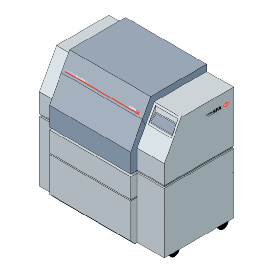
Parts of the Imagesetter The SelectSet Avantra imagesetter is designed for ease of use. This sec- tion describes the basic components. Media Compartment The media compartment contains the supply cassette, the take-up cas- sette, and cutter. • Supply Cassette Holds unexposed media. You load it with bulk rolls of media. - Page 24 Figure 1.1. The SelectSet Avantra Imagesetter. —Media compartment. —Main power switch. —Control panel 501.ArrowCabinet.art Getting Acquainted • 1–3...
-
Page 25: The Control Panel
Status icons on the screen display information about the imagesetter. Some icons act as buttons. You press these button icons to operate the imagesetter. See Figure 1.2. Figure 1.2. The SelectSet Avantra control panel showing the Pause Screen. 1–4 • SelectSet Avantra User Guide... -
Page 26: Specifications And Features
• Internal drum imaging system Yields the precise registration required to image multi-color jobs. • Reloadable supply cassette The SelectSet Avantra uses a reloadable supply cassette that ac- cepts daylight loading or darkroom loading media. • Media Optimization You can program the imagesetter to rotate jobs for most efficient use of media. -
Page 27: Options
Enables punching of media to facilitate registration of multicolor jobs. • Upgrade Option The SelectSet Avantra 20 can be upgraded to a SelectSet Avantra 25. All options are available to systems that have been upgraded. • Extra Cassettes Extra media supply cassettes and take-up cassettes can help you operate more efficiently. - Page 28 The following table lists the extra-cost options: Option SelectSet Avantra 20 SelectSet Avantra 25 On Line Processor DualSupply FlexMedia Registration Punches: Head Punch Stoesser only Stoesser or Bacher Tail Punch Stoesser or Bacher Custom Upgrade Option Getting Acquainted • 1–7...
-
Page 29: Your Imaging System
2. It converts this data to a form that can be used by the imagesetter. The SelectSet Avantra can be used with a wide choice of software and hardware RIPs. • Software RIPs run on standard computer platforms. These standard platforms can serve other functions when not used as RIPs. -
Page 30: Safety Information
SelectSet Avantra. Laser Information The SelectSet Avantra imagesetters are classified as Class I laser de- vices. The maximum accessible radiation level during operation and maintenance is less than Class I limits. This means that you are not exposed to any hazardous laser radiation during operation and main- tenance. -
Page 31: Laser Safety Instructions
These covers and interlocks have warning labels located near them. Re- moval of covers or bypassing the interlocks may expose you to laser ra- diation that is considered hazardous according to Code of Federal Reg- ulations, section 1040.10. 1–10 • SelectSet Avantra User Guide... -
Page 32: General Safety Instructions
General Safety Instructions 1. Turn off power, then unplug the imagesetter from the wall outlet be- fore cleaning. Use only a damp cloth. Do not use liquid or aerosol cleaners. 2. Do not use the imagesetter in any area near water. 3. -
Page 33: Sound Level
CFR Subchapter J in effect as of the date of manufacture. Figure 1.4. CDRH compliance label, located on the rear panel. It reads: This product conforms to all applicable provisions of 21 CFR, subchapter J in effect as of the date of manufacture. 1–12 • SelectSet Avantra User Guide... - Page 34 CLASS 1 LASER LASER KLASSE 1 Figure 1.5. Laser class label, located on the rear panel of the unit. Indicates the class of laser radiation during operation and maintenance. Note: Class I lasers are considered safe for opera- tor access in accordance with the Code of Federal Regulation and international standards.
-
Page 35: Chapter 2: Basic Control Panel Operations
Chapter 2: Basic Control Panel Operations... -
Page 36: Introduction
Introduction This chapter provides an introduction to the SelectSet Avantra control panel. It contains the following information: • How to start and shut down the imagesetter • Features of the control panel • Introduction to the control panel screens • Basic controls for use in the control panel screens •... -
Page 37: Start Up And Shut Down Procedures
SelectSet Avantra Diagnostics Startup V.1.01 Figure 2.1. Screens that appear as you start up the SelectSet Avantra. Step 2: When the control panel displays message 15 (No RIP), turn on the RIP. Follow the instructions in the manuals that come with your RIP. -
Page 38: Shut Down Procedure
Step 4: Turn on the other parts of your imaging system. Step 5: To ensure consistent results, let the imagesetter run for twenty minutes before you begin to image jobs. Shut Down Procedure To shut down the imagesetter, turn off the power at the control panel. About the Control Panel •... -
Page 39: Control Panel Screens
Note: If there is no media loaded, or if there is no take-up cassette in place, or if the bridge for the on-line processor is out of position, the Pause Screen appears instead of the Run Screen when you start up the imagesetter. 2–4 • SelectSet Avantra User Guide... - Page 40 Pause Cassette Setup Feed Amounts Utilities Configuration Figure 2.3. Press the square cornered buttons in the Pause Screen to access the other control panel screens. Basic Control Panel Operations • 2–5...
-
Page 41: Basic Controls
Minus. Cancel: Discards any changes in the current screen. Accept: Accepts the parameters that appear on the screen. Figure 2.4. Left: Run Screen. Abort; Pause. Right: Pause Screen. Abort; Run. 2–6 • SelectSet Avantra User Guide... -
Page 42: Special Features Of Plus And Minus
Special Features of Plus and Minus • Interchangeable Press either Plus or Minus to make selections. • Cycling through selections The different selections for a function act as if they are on a loop. When you reach the end of the possible selections or numerical val- ues, the list begins again. -
Page 43: Using Functions
Cassette Number Feed Amounts Media Type Feed Feed Amount Punches Reverse Feed Feed/Cut Amount Media Thickness Switch Supply Interpage Gap Media Amount Supply Alarm Media Width Take-up Alarm Exposure Distance to Punches Test Page 2–8 • SelectSet Avantra User Guide... -
Page 44: To Set A Parameter
To Set a Parameter • Press the icon that represents the parameter you need to change. • Select the desired setting. Use Plus or Minus. • Confirm your selection. Press Accept to keep or Cancel to discard changes. In some cases, you select from limited choices. This example shows how to set the imaging mode in the Configuration Screen. - Page 45 3. Accept or Cancel: Press Plus or Minus to change Press Accept to change the media amount. the media width, or… Range: …press Cancel to discard. 0.0 to 250.0 feet 0.0 to 76.2 meters 2–10 • SelectSet Avantra User Guide...
-
Page 46: Press Some Buttons Twice
Load Supply A Press Some Buttons Twice Load Supply B To activate some functions, you need to press a button twice. For ex- (Available only with DualSupply Option.) ample: To Load a Supply: Press once and the icon Press again to complete flashes. -
Page 47: Chapter 3: Using The Control Panel
Chapter 3: Using the Control Panel... -
Page 48: Introduction
Many of the functions you perform at the SelectSet Avantra control panel can also be performed by downloading RIP user tools to your RIP. Certain features of the SelectSet Avantra can be activated only by RIP user tools. For more information, see Appendix C: RIP User Tools in this user guide and refer to your RIP documentation. -
Page 49: The Run Screen
Startup Abort Pause Operating Modes The SelectSet Avantra has three operating modes in the Run Screen: • Idle: Ready to image a job • Busy: Imaging a job • Pause Pending: The imagesetter will go into Pause when the job... -
Page 50: Current Job Information
Current Job Information • The name of the job being imaged appears over the progress bar. This information is cleared when the job is finished. • A limited number of spaces are available to display the name. Job names that are too long are cut from the left. •... -
Page 51: The Pause Screen
The Pause Screen Load Supply A Load Supply B (Available only with DualSupply Option.) Cassette Setup Feed and Cut Feed Amounts Unload Utilities Configuration Display Job History 3–4 • SelectSet Avantra User Guide... -
Page 52: Load A Media Supply
Load Supply A Load a Media Supply Load Supply B When you press Load, the imagesetter advances media from a supply (Available only with DualSupply Option.) cassette into the drum. To Load a Supply: Press once and the icon Press again to complete flashes. -
Page 53: Unload
…press Abort to cancel. 3. Rewinds the media in the drum back into the supply cassette. To Unload: Press once and the icon Press again to complete flashes. unloading or… …press Abort to cancel. 3–6 • SelectSet Avantra User Guide... -
Page 54: Display Job History
Display Job History When you press Display Job History, the imagesetter displays the names of the last five jobs that have been imaged. 1. Press Pause, then Display Job History. Job Number One 1, 1, 1 Job Number Two 2, 1, 1 Job Number Three 3, 1, 1 Job Number Four... -
Page 55: Run And Pause Status Icons
—Media status, supply B (appears only with DualSupply Option). —Engine status. —Job status. Media Status Figure 3.4. The media status display. —Media width. —Top punch. —Bottom punch. —Media remaining. —Media type, alignment mode, imaging mode. —Cassette number. 3–8 • SelectSet Avantra User Guide... - Page 56 Figure 3.5. The display changes to show that a media supply is loaded. Left, DualSupply A loaded. Right, DualSupply B loaded. Figure 3.6. Punch modes. Adjust in Cassette Screen. These symbols are used as a convention to represent the many different punch configurations that are available.
- Page 57 —Negative right reading. —Negative wrong reading. The three media types are listed top to bottom. You change media type in the Cassette Screen. A—Film. B—Paper. C—Plate. Figure 3.9. Cassette number. Adjust in Cassette Screen. 3–10 • SelectSet Avantra User Guide...
-
Page 58: Engine Status
Engine Status Figure 3.10. Engine status changes when you specify an on line proces- sor in the Configuration screen. Figure 3.11. Left, take-up cassette out. Right, take-up cassette in. Using the Control Panel • 3–11... - Page 59 Figure 3.12. Media loaded. Left, single media supply. Right, DualSupply. 3–12 • SelectSet Avantra User Guide...
-
Page 60: Job Status
Job Status Figure 3.15. Job status display. Run Screen (left) and Pause Screen (right). —Current resolution. —Current exposure. —Media past the cutter. —Job counter. Current Resolution: The current resolution being used by the image- setter is displayed. • The imagesetter changes resolution based on commands embedded in the file that is being imaged or commands downloaded to the RIP from the front end. -
Page 61: Supply Alarm
• The imagesetter continues imaging until the supply cassette is com- pletely empty. At this point, error message 4, Out of Media, appears on the control panel. Figure 3.13. Supply alarm. Appears in both the Run and Pause screens. 3–14 • SelectSet Avantra User Guide... -
Page 62: Take-Up Alarm
Take-up Alarm • You specify the Take-up Alarm amount in the Feed Amounts Screen. • When the media fed into the take-up cassette exceeds this amount, an alarm appears. • The alarm blinks and the imagesetter goes into Pause Pending; it will go to Pause when the current job is finished. -
Page 63: The Cassette Setup Screen
1, 2, 3, 4 or 5. Media Type Choices: F = Film P = Paper PL = Plate Punches Choices: (Optional) Punches disabled Head punches only Tail punches only Head & tail punches more… 3–16 • SelectSet Avantra User Guide... - Page 64 Cassette Setup, continued… Media Thickness Range: (Available only with FlexMedia Option) 3 to 8 mil .08, .10, .13, .15, .18 or .20 mm Media Amount Range: 0.0 to 250.0 ft 0.0 to 76.2 m Media Width Range: Avantra 20 Avantra 25 9.75 to 14 in.
-
Page 65: Exposure Settings
Run tests for each media type and each imaging resolution before you begin production. See Chapter 5: Exposure Tests for information about running and eval- uating test pages. See Appendix A: Image Quality for more information about exposure settings. 3–18 • SelectSet Avantra User Guide... -
Page 66: Cassette Parameters
You can define up to five different sets of cassette parameters. If you define and use cassette parameters, you can change a group of pa- rameters on the SelectSet Avantra just by selecting a different cassette number. Consider this example: A shop uses film in three different widths. -
Page 67: Specifying A Cassette Number
• Cassette 1 is specified as Supply A. • You select Supply B. • You can specify cassettes 2, 3, 4 or 5 for Supply B. • You cannot specify cassette 1 for Supply B. 3–20 • SelectSet Avantra User Guide... -
Page 68: List Of Cassette Parameters
List of Cassette Parameters This table lists the different cassette parameters and provides space for recording the settings you use. Make a copy of this form to keep in your work area. Cassette Number ___1 ___2 ___3 ___4 ___5 Media Type _______ _______ _______... -
Page 69: The Feed Amounts Screen
Feed Amount Range: 0.0 to 39.0 in 0 to 99 cm Feed Cut Amount Range: 0.0 to 39.0 in 0 to 99 cm Interpage Gap Range: 0.0 to 10.0 in 0 to 25.4 cm more… 3–22 • SelectSet Avantra User Guide... -
Page 70: Definitions
Feed Amounts, continued… Supply Alarm Range: 0.0 to 250.0 ft 0.0 to 76.2 m Take-up Alarm Range: 0.0 to 100.0 ft 0.0 to 30.5 m Distance to Punches Range: 0.48 to 10 in. 12 to 254 mm Definitions Feed Amount: Media fed when you use Feed in the Utilities Screen or when you send a feed command from your front end. -
Page 71: The Utilities Screen
The Utilities Screen Press Pause, then Utilities. Retract Punches and Nips Feed Switch Supplies Reverse Feed 3–24 • SelectSet Avantra User Guide... -
Page 72: To Use Utilities Functions
To Use Utilities Functions 1. Select a function. For example, press cut. 2. Press Accept. Press once and the icon Press again to confirm or… flashes. …press Abort to cancel. Definitions Retract Punches and Nips: Rollers called nip rollers and punches hold media in place. -
Page 73: The Configuration Screen
The Configuration Screen Press Pause, then Configuration. Image Mode Choices(l to r): Positive Right Read Positive Wrong Read Negative Right Read Negative Wrong Read Autocentering Choices: Flush left Centered Units of Measurement Choices: English Metric more… 3–26 • SelectSet Avantra User Guide... -
Page 74: Definitions
Configuration, continued… Processor Timeout Range: 0 to 255 minutes Viewing Angle Range: 1 to 32 Volume Range: 1 to 5 Output Mode Choices: Take-up cassette On-line processor Definitions Processor Timeout: For use with on-line processor. Sets time delay after last job. When the delay period ends with no activity at the im- agesetter, the last job is advanced, cut, and fed to the processor. -
Page 75: Image Mode
• Negative Right Reading: Type and images unexposed; background exposed. Right reading with the media emulsion side up. • Negative Wrong Reading: Type and images unexposed; background exposed. Right reading with the media emulsion side down. 3–28 • SelectSet Avantra User Guide... -
Page 76: Chapter 4: Media Operations
Chapter 4: Media Operations... -
Page 77: Introduction
Introduction This section describes: • Loading media into supply cassettes. • Installing loaded supply cassettes into the imagesetter. • Removing supply cassettes from the imagesetter. • Using take-up cassettes: Loading them into the imagesetter, re- moving them from the imagesetter. Media Operations •... -
Page 78: Loading Media Into Supply Cassettes
Figure 4.2. Remove the empty media roll. Loosen the outer locking knob Remove the endcaps from both ends of the roll. Loosen the outer locking knob, then tap the bearing with the palm of your hand. 4–2 • SelectSet Avantra User Guide... - Page 79 Figure 4.3. Remove the endcaps. Step 2. Adjust the endcaps to match the media width. Loosen the small locking knob. If necessary, use the special wrench supplied with the imagesetter to loosen the knob. Figure 4.4. Loosen the small locking knob .
- Page 80 Place the media roll in the cassette. Put the new media roll into the cassette. Make sure that the end cap with the gear goes to the right. Use your thumb to smooth paper against and over both end- caps. 4–4 • SelectSet Avantra User Guide...
- Page 81 Step 5. Open the media wrapper and close the cassette. Figure 4.8. Close the cassette and pull the media wrapper out of the cassette. Remove the tape that secures the media wrapper. Pull the wrapper so that it hangs over the edge of the supply cassette. Close the cassette, then slowly pull the wrapper out of the cassette until you see the media.
-
Page 82: Installing Loaded Supply Cassettes
On systems with the DualSupply Option, make sure that the rollers are open to receive media from the supply cassette you are inserting. If not, use Switch Supplies in the Utilities Screen. Close the light shield and top cover. 4–6 • SelectSet Avantra User Guide... - Page 83 Step 2. Update the cassette parameters. Press Pause, then Cassette Setup. Select Select A or B Supply Cassette Does the correct cassette Number number appear? Media Amount Reset the Media Amount. Range: 0.0 to 250.0 ft 0.0 to 76.2 m Make sure that the correct cassette number is assigned to the supply cassette.
- Page 84 Press Load to feed media from the supply into the imageset- ter drum. Load Supply A Load Supply B (Available only with DualSupply Option.) To Load a Supply: Press once and the icon Press again to complete flashes. loading or… …press Abort to cancel. 4–8 • SelectSet Avantra User Guide...
-
Page 85: Removing Supply Cassettes
Removing Supply Cassettes Step 1. Unload the media supply. If there is media in the take-up cassette, the imagesetter au- tomatically does a feed and cut when you unload a media supply. In this case, you need to remove the take-up cassette before you can load another supply cassette. - Page 86 If you rewind the media too far, you need to open the cassette in a darkroom to pull the end out. Opening the cassette in normal room light will expose a large quantity of the media in the cas- sette. 4–10 • SelectSet Avantra User Guide...
-
Page 87: Take-Up Cassettes
Take-up Cassettes The take-up cassette is motor driven. This feature makes is possible for the cassette to receive up to 100 feet (30 m) of exposed media. Figure 4.12. The take-up cassette. Figure 4.13. The take-up cassette area. Note the location of the drive motor . Media Operations •... -
Page 88: Removing Take-Up Cassettes
3. Line up the cassette with the cassette sensor and the take-up drive wheel and press it down into position. Make sure that the cassette is securely in place. 3. Close the lower front cover. 4–12 • SelectSet Avantra User Guide... -
Page 89: Opening And Closing The Media Slot
Figure 4.15. Inserting the take-up cassette. Opening and Closing the Media Slot The opening in the take-up cassette is called the media slot. A lever at the end of the cassette opens and closes this slot. • To open the slot, press the lever in and turn it counter-clockwise. •... -
Page 90: Chapter 5: Exposure Tests
Chapter 5: Exposure Tests... -
Page 91: Introduction
Introduction This chapter describes how to run exposure tests and how to evaluate these tests to determine optimum exposure settings for the SelectSet Avantra. The following topics are covered: • A description of the test page • Running exposure tests •... -
Page 92: The Test Page
• A reference band near the center of the page is imaged at the cur- rent exposure set in the Cassette Screen. The reference band is indented at the left end of the test page. See in Figure 5.1. 5–2 • SelectSet Avantra User Guide... - Page 93 • The resolution is indicated by a bar code. See Figure 5.2. 1200 dpi 1800 dpi 2400 dpi 3600 dpi Figure 5.2. Bar codes indicate the resolution (dpi value) used to image a test page. • The increment, or difference in the exposure setting from one band to the next, is indicated by indents at the right end of the test page.
-
Page 94: The 4 Dpi's Test Page
• Each image uses a different resolution. • The reference band for each image is exposed at the current setting for that resolution. • All four images use the same increment value. Figure 5.4. The 4 dpi’s test page. 5–4 • SelectSet Avantra User Guide... -
Page 95: Running Exposure Tests
• When you change emulsion batches. (The product label attached to each case and each roll of Agfa photographic media is stamped with a number that identifies the emulsion batch.) • When you load a new roll of media or when you replace the chemi- cals in your media processor. -
Page 96: How To Image An Exposure Test Page
• Expect each resolution to have a unique optimum exposure. 5–6 • SelectSet Avantra User Guide... - Page 97 When you image a test page, the imagesetter advances the exposed media out of the drum. While the test page is being imaged, a progress bar appears in the Cas- sette Screen. 4 dpi’s Note: When you use an on-line processor, the Se- lectSet Avantra automatically advances, cuts, and feeds an imaged test page to the processor.
-
Page 98: Reading A Test Page
Step -2 (current exposure) - (2 x increment value) Step -3 (current exposure) - (3 x increment value) Lower exposures toward the bottom of the page… Figure 5.5. To read a test page, hold it like this. 5–8 • SelectSet Avantra User Guide... - Page 99 For example, if the current exposure setting is 592 and the increment value is 10: Higher exposures… Step +3 (592) + (3 x 10) = 592 + 30 = 622 Step +2 (592) + (2 x 10) = 592 + 20 = 612 Step +1 (592) + (1 x 10) = 592 + 10 = 602 Reference band (592) Step -1 (592) - (1 x 10) = 592 - 10 = 582...
-
Page 100: Evaluating Test Pages
After you evaluate a test page and determine the optimum exposure for each combination of media and resolution, you need to set the expo- sure values. This procedure is described in Chapter 3: Using the Con- trol Panel. 5–10 • SelectSet Avantra User Guide... -
Page 101: Chapter 6: Diagnostics And Error Messages
Chapter 6: Diagnostics and Error Messages... -
Page 102: Introduction
Introduction This chapter contains: • Information about error messages. • Procedures for clearing error messages from the control panel. • Procedures for using the internal modem for error reporting. • Procedures for bypassing boot errors. Diagnostics and Error Messages • 6–1... -
Page 103: Error Procedures
To correct some errors, you need to reset the system. Step 1: Turn the imagesetter off and let it remain idle for a few min- utes. Step 2: Restart the imagesetter. You may also need to reboot the RIP before you can continue. 6–2 • SelectSet Avantra User Guide... -
Page 104: Error Messages
Error Messages This section lists the error codes and describes corrective action. 1 Carriage Jam Motion of the carriage has been blocked. Reset the imagesetter and retry the original operation. If the error returns immediately, the carriage may be getting caught on media in the drum. - Page 105 12 Hardware Error Reset. If the error persists, call for service. 13 Left Side Door Open The left door is not securely closed. Close the door. When you clear the message, the image- setter resets itself. 6–4 • SelectSet Avantra User Guide...
- Page 106 14 RIP Data Error The RIP sent more data than it specified. Reset. Process the job that generated the error. Make sure that it is complete. If the error persists, call for service. 15 No RIP Check to see if your RIP is running. Check cable connec- tions between RIP and imagesetter.
- Page 107 Reset and retry the command. If the error persists, call for service. 32 Carriage Position Error The system detected a problem with the carriage while imaging. Reset. If the error persists, call for service. 6–6 • SelectSet Avantra User Guide...
- Page 108 33 No Media Currently Loaded Go to the Pause Screen and load a media supply. 34 Media in Take-up Cassette There is cut media in the take-up cassette. Remove the cassette. Put an empty cassette in the imagesetter in its place.
- Page 109 Figure 6.1. Make sure that the bridge is completely lowered. 42 Right Side Door Open The right door is not securely closed. Close the door. When you clear the message, the image- setter resets itself. 6–8 • SelectSet Avantra User Guide...
- Page 110 43 Internal Error Reset. Call for service if the error persists. 44 Cut Not Allowed Not enough media has been fed past the cutter. If this message appears when you use Cut in the Utilities Screen, clear the message, press Feed, then press Cut again.
- Page 111 Look for media in the lower section of the bridge. If you find no media in the bridge, lift the bridge up and look for media protruding from the media slot. See Figures 6.2 and 6.3. 6–10 • SelectSet Avantra User Guide...
- Page 112 53 Bridge Jam At Processor Entry Open the media compartment and remove the top bridge cover. Look for media caught near the entry to the media pro- cessor. See Figures 6.2 and 6.3. 54 Bridge Jam After Center Sensor Open the media compartment and remove the top bridge cover.
- Page 113 Figure 6.2. Bridge for the on-line processor. —Top cover. —Bottom cover. Figure 6.3. Locations on the bridge media path. —Media slot. —Lower section. —Top section. —Entrance to media processor. 6–12 • SelectSet Avantra User Guide...
- Page 114 57 Processor Error The on-line processor is reporting an Input Jam, an Exit Jam, or a Motor Overload error. Clear the error and check the on-line processor control panel. For more information, see the section Processor Status and Error Messages in chapter 9. The imagesetter will abort the current job, and will not image another job or advance media until the processor error is cleared.
- Page 115 Errors 100 and Above Error messages numbered 100 and above are reported by diagnostic software that the imagesetter runs as it boots up. For more informa- tion, see the section Boot Errors in this chapter. 6–14 • SelectSet Avantra User Guide...
-
Page 116: Special Error Procedures
Special Error Procedures This section contains detailed procedures for clearing errors. Unload Media Using the Utility Screen Follow this procedure to unload media using the functions in the Util- ities Screen. • Go to the Utilities Screen. • If there is media in the take-up cassette, press Cut then Accept to cut it. -
Page 117: Overriding Error 44: Cut Not Allowed
Note: Use this override only if you are absolutely sure that at least 5" (12.7 cm) of media is past the cutter. If the cut produces a sliver of media less than 5" long, you may have trouble removing it. 6–16 • SelectSet Avantra User Guide... -
Page 118: Remote Diagnostics
To activate the modem and have it dial out to the remote diagnostic computer, press the Dial Out icon button that appears when the sys- tem is booting up. SelectSet Avantra Diagnostics Startup V.1.01 While the modem is active, the control panel looks like this:... -
Page 119: Boot Errors
Boot Errors The SelectSet Avantra runs a diagnostic program as it boots up. If the diagnostic program detects an error: • When the internal modem is connected, the imagesetter automati- cally dials out to the remote diagnostic unit. • When the internal modem is not connected, the error icon remains on the control panel. -
Page 120: Bypassing Boot Errors
Bypassing Boot Errors Startup SelectSet Avantra Diagnostics Startup V.1.01 Press Plus to bypass the boot error. Follow this procedure to bypass boot errors. 1. Restart the imagesetter. 2. When the boot error is detected, an error icon and the Plus icon but- ton appear on the screen. -
Page 121: Chapter 7: Maintenance And Troubleshooting
Chapter 7: Maintenance and Troubleshooting... -
Page 122: Introduction
Introduction This chapter contains: • Procedures for clearing media jams. • Basic maintenance procedures. Maintenance and Troubleshooting • 7–1... -
Page 123: Clearing Media Jams
Remove Nip Drive Assembly Figure 7.1. Front view showing location of the nip drive assembly. WARNING: The nip drive assembly weighs approximately sev- en pounds (3.2 kilograms). 7–2 • SelectSet Avantra User Guide... - Page 124 Step 1: Turn off the imagesetter. Step 2: Open both the left and right side doors. Step 3: Remove the front cover. • Hold on tightly to the top edge of the cover and pull it away from the imagesetter. •...
- Page 125 • Reconnect the wires. Step 8: Put the light shield back in place. Step 9: Put the front cover back on the imagesetter and close both side doors. Step 10: Start the imagesetter and resume operations. 7–4 • SelectSet Avantra User Guide...
-
Page 126: Clear Media From Drum: Access From The Left
Clear Media from Drum: Access from the Left Step 1: Turn off the imagesetter. Step 2: Open the left side door. Step 3: Remove the left drum cover. • Loosen the four latches that hold it in place. Figure 7.3. The imagesetter with the left side door open showing the drum cover. —Latches. - Page 127 Push the inner shield all the way onto the carriage, until the stops on the shield touch those on the carriage. Step 8: Put the drum cover back on and secure the latches. Step 9: Close the left side door and start the imagesetter. 7–6 • SelectSet Avantra User Guide...
-
Page 128: Clear Media From Drum: Access From The Right
Clear Media from Drum: Access from the Right Step 1: Turn off the imagesetter. Step 2: Open the right side door. Step 3: Remove the right drum cover. • Loosen the four latches that hold it in place. Figure 7.4. The imagesetter with the right side door open showing the drum cover. —Latches. - Page 129 Push the inner shield all the way onto the carriage, until the stops on the shield touch those on the carriage. Step 8: Put the drum cover back on and secure the latches. Step 9: Close the right side door and start the imagesetter. 7–8 • SelectSet Avantra User Guide...
-
Page 130: Clear Media From Input Side
Clear Media from Input Side Step 1: Turn off the imagesetter. Step 2: Raise the top cover. • If your imagesetter is equipped with an on-line bridge, lift the bridge up and out of the way. Step 3: Remove the plastic light shield that covers the front of the media supply area. - Page 131 Step 10: Start the imagesetter and resume operations. Figure 7.5. Left, view of the imagesetter showing location of the light shields and latches. Right, removing the light shield. 7–10 • SelectSet Avantra User Guide...
-
Page 132: Maintenance
Maintenance The only maintenance you need to perform on your SelectSet Avantra is to keep it clean. To help keep your imagesetter clean, keep your work area as clean as possible. Follow these guidelines when cleaning the inside of the imagesetter: •... -
Page 133: Interior
Method: Vacuum or wipe clean. Take-up Cassettes Clean the inside of take-up cassettes. Interval: Once a month. Method: Vacuum or wipe clean. Open the take-up cassette by removing the four screws that hold the lid and base together. 7–12 • SelectSet Avantra User Guide... -
Page 134: Supply Rollers
Supply Rollers Clean the surface of the supply rollers in the media supply compart- ment. Interval: Once a week or as dirt and contamination is observed on the rollers. Method: Remove supply cassettes. Use plastic packing tape. Wrap tape around your hand with the sticky side out and press against the rollers to pick up dirt. -
Page 135: Intake Filters
Interval: Once a month or more frequently if necessary. Method: Shut down the imagesetter. Pull out the filter and replace it. Use part number C00305-001. Contact your service provider for information about ordering replacement filters. 7–14 • SelectSet Avantra User Guide... -
Page 136: Punch Trays
Punch Trays Check the punch trays every three months. Follow this procedure to empty them. Step 1: Turn off the imagesetter. Step 2: Open the left side door. Step 3: There are two punch trays, both below the imaging drum. They are bright red. -
Page 137: Chapter 8: Avantra 20/25 Olp Bridge Operation
Chapter 8: Avantra 20/25 OLP Bridge Operation... -
Page 138: Introduction
Avantra 20/25 OLP. It contains the following information: • Description and overview of the entire Avantra 20/25 OLP unit. • How to set up the SelectSet Avantra to work with an on line pro- cessor. • The operating sequence that the bridge follows. -
Page 139: Product Description
Product Description The SelectSet Avantra 20/25 OLP consists of: • A transport mechanism that feeds exposed media from the image- setter to the processor. This is called the bridge. The bridge also pro- vides the communication link between the processor and the imagesetter. - Page 140 Figure 8.1. Exterior view of the SelectSet Avantra and OLP Figure 8.2. Cutaway view of the SelectSet Avantra and OLP showing the media path. —Imagesetter. —Bridge. —Processor. Avantra 20/25 OLP Bridge Operation • 8–3...
-
Page 141: Set Up The Processor Option
OLP (right) The button shows the current output mode. Take-up cassette selected. OLP selected. Note: Make sure that you remove the take-up cas- sette and that the bridge is completely lowered into its operating position. 8–4 • SelectSet Avantra User Guide... -
Page 142: Special Points To Remember
Special Points to Remember Keep these points in mind when you select on-line processor output mode. • The imagesetter disregards the interpage gap amount specified in the Feed Amounts Screen. Instead, it uses a value of .8 inches (2 cm). •... -
Page 143: Bridge Operating Sequence
• If a media feed pushes enough media past the cutter to enable a cut, the Pause Screen remains on the control panel and this ani- mated icon appears. 8–6 • SelectSet Avantra User Guide... -
Page 144: To Optimize Output
• When you go to the Pause Screen to perform feed or cut operations yourself, the imagesetter may have to delay these actions if media is already moving onto the bridge. In such cases, the icon in the bot- tom left corner of the Pause Screen changes. The changed icon flashes until the cut media has advanced far enough onto the bridge to leave room for the piece about to be cut. -
Page 145: Clearing The Bridge Media Path
• Rollers inside the bridge guide the media. • These rollers can move in one direction only—toward the processor. Keep this in mind if you are about to pull a piece of media out of the bridge. 8–8 • SelectSet Avantra User Guide... - Page 146 Imagesetter. Bridge. Processor. Nip rollers and cutter. Bridge entry sensor. Bridge center sensor. Bridge to processor mechanical interface. Figure 8.3. Cutaway view showing key parts of the media path through the bridge. Avantra 20/25 OLP Bridge Operation • 8–9...
-
Page 147: Bypassing The Bridge
When your jobs are complete, feed and cut the media, re- move the cassette, and process the media. Figure 8.4. You can put the standard take-up cassette into the processor to bypass the bridge. 8–10 • SelectSet Avantra User Guide... -
Page 148: Chapter 9: Avantra 20/25 Olp Processor Operation
Chapter 9: Avantra 20/25 OLP Processor Operation... -
Page 149: Introduction
Introduction This section describes the media processor section of the Avantra 20/25 OLP. It contains the following information: • The use of the Avantra 20/25 OLP Control panel. • How to set times, temperatures, replenishment rates, and various other functions. Also provided is a table that you can use to record your nine preferred operating programs When your processor is first installed, a service representative sets up... -
Page 150: Processor Description
Processor Description The Avantra 20/25 OLP processor provides rapid access processing for a wide variety of photographic materials. Features • Types of media: paper, film, and plate material. • Adjustable time and temperature controls. • Handles media up to 20 inches (51 cm) wide. •... -
Page 151: The Processor Control Panel
The Processor Control Panel The control panel consists of the following: • Display: An LED display that shows status and error messages • Alarm signals: LED warning lights that appear below the display • Status signals: LED lights that appear below the display •... -
Page 152: Idle State
Idle State Current program Program 1 is selected. DEV 35 C Developer temperature 35° centigrade.(Actual) 35 S Developer time 35 seconds. On/Off mode M=Manual On/Off; A=Auto On/Off This display appears when the processor is ready to process media. Note: This is just an example. The actual numbers that appear on your display may vary if you specify different parameters. -
Page 153: Alarm Signals
• Repl. Empty: Low level in the replenishment containers • Waste Full: N/A The SelectSet Avantra displays error 27, Processor Alarm Signal when any of these errors occur. In this case, the imagesetter finishes the cur- rent job, but will not image another job or advance media until you clear the processor error. -
Page 154: Automatic Functions
Automatic Functions The processor performs these functions automatically after you turn it • Jog Function • Automatic Start and Stop Jog Function Every five minutes, when the processor is on but not processing media, an internal timer activates these functions for one minute: 1. -
Page 155: System Clock
System Clock The processor has an internal clock that runs continuously, even when the processor is off. This clock is used to turn the processor on and off automatically and to control standby replenishment. The internal clock operates in a 24 hour mode. For example, 5:00 PM is shown as 17:00 hours. -
Page 156: Changing The Time
Changing the Time Press TIME to display the current day and time. For example: MON 10:39 Follow this procedure to change the settings. Step 1: Press TIME then PRESET. The display shows the current day setting. Step 2: To change the day, press plus (+) or minus (-). Step 3: Press ENTER. -
Page 157: Auto On/Off
Auto On/Off You can set up the processor to turn itself on and off automatically at specific times, or you can turn it on and off manually. Select On/Off Mode, Display On/Off Time Pressing the AUTO key: 1. Displays the current auto on time. 2. -
Page 158: Setting On And Off Time
Setting On and Off Time Step 1: Press Auto. The current auto on time appears. Step 2: Press Preset. The display reads MO-FR. Step 3: To change the day, press plus (+) or minus (-). Step 4: Press Enter. This displays the current hour setting. Step 5: To change the hour, press plus (+) or minus (-). -
Page 159: Checking The On/Off Selection
Checking the On/Off Selection If you intend to use auto on/off after you set the times, check the con- trol panel display to make sure that auto on/off is active. • When manual on/off is active, the control panel display shows the letter M at the right. -
Page 160: Checking Preset Values
Checking Preset Values You can check any preset value at any time. For example, to check the fixer temperature and compare it with the preset value, follow these steps: Step 1: Press Fix and Temp. • The actual fixer temperature appears. For example: FIX TEMP 33 C Step 2: Press Preset while the actual temperature is displayed. -
Page 161: Changing The Developer Time
Changing the Developer Time Follow these steps to change the developer time. Step 1: Press DEV and TIME. • The current developer time appears. For example: DEV TIME 16 SEC Step 2: Press PRESET. • The preset developer time appears. For example: DEV SET 16 SEC Step 3: Press plus (+) or minus (-) to change the setting. -
Page 162: Changing Temperature
Changing Temperature Follow this procedure to change the developer temperature. Step 1: Press DEV TEMP. • The actual developer temperature appears. For example: DEV TEMP 32 C Step 2: Press PRESET. • The preset developer temperature appears. For example: DEV SET 32 C Step 3: Press plus (+) or minus (-) to change the setting. -
Page 163: Changing Replenishment Rates
Changing Replenishment Rates Follow this procedure to change the replenishment rate. Step 1: Press DEV and REPL. • The current developer replenishment rate appears. For example: DEV REPL 200 CC Step 2: Press PRESET. • The preset rate appears. For example: DEV SET 200 CC Step 3: Press plus (+) or minus (-) to change the setting. -
Page 164: Standby Replenishment
Standby Replenishment Standby replenishment compensates for exhaustion of the developer due to oxidation and depletion of the fixer due to evaporation. The replenishment pump releases 100 cc. of chemistry each time it is activated. You specify the amount of replenishment required for an entire day. -
Page 165: Other Functions
Other Functions Sound Press SOUND to switch the audible “beep” on or off. The “beep” sounds when the trailing edge of the material being pro- cessed clears the film input sensor. This signal also indicates that you can insert the next piece of media to be processed. Pan Light Controls the brightness of the LED display. -
Page 166: Dryer Saver
Dryer Saver When this function is On (the default setting), the dryer is in standby mode. When switched to Off, the display reads DRYER SAVER OFF and the heating elements and dryer run continuously at the preset temperature. Man. Repl. Controls manual replenishment of developer and fixer. -
Page 167: Density 15%, 50%, 85
Density 15%, 50%, 85% Replenisher quantities for developer and fixer are calculated according to a formula based on the preset value, the area of the material (width x length), the percentage density, and the replenisher information (cc. per square meter). This last information is listed on the material box or in documentation provided by the media manufacturer. -
Page 168: Offline Operation
Offline Operation You can bypass the bridge and feed media directly into the processor from a take-up cassette. Built into the front of the processor is a lid. Below the lid is an input tray with various foam light seal adapters, for use with different size take-up cassettes. -
Page 169: Programming
Programming The processor can store nine different programs that control develop- ing time, dryer temperature, and and replenishment rates. Programs 1, 2, and 3 are preset with the values listed below. Preset Values Function (Unit) Program 1 Program 2 Program 3 Dev. - Page 170 9–22 • Avantra User Guide...
-
Page 171: Processor Maintenance
Processor Maintenance This section describes daily, weekly, and monthly maintenance rou- tines. Proper maintenance of your processor is essential to getting the best possible photographic results from your imaging system. Follow a regular maintenance program. A thorough cleaning at least once a month is strongly recommended. -
Page 172: Weekly Maintenance
• Wipe down all rollers above the solution level. Use a separate rag for developer rollers. A cleaning sheet can be used as an alternative to wiping down the rollers. A cleaning sheet can be any pre-processed media that is at least 18 inches (46 cm) long. - Page 173 • Drain the processor. Dispose of developer, fixer, and wash water according to local reg- ulations. • Drain the filter housing. Remove the filter. Change the filter every 40 working hours. • Remove roller racks and wipe residue from tanks. Use paper towels to remove sludge or residue from tanks.
- Page 174 • Fill fixer tank. Be careful not to splash fixer into the developer tank. When filling tanks without roller racks in place, fill tanks to the line of the drain tube. Wipe up any spills. CAUTION: Be careful not to spill any fixer into the developer when lifting the racks out of a full tank.
-
Page 175: Monthly Maintenance
Monthly Maintenance Once a month, add the following to your weekly maintenance proce- dure. • Pull the developer, fixer and wash roller racks. Inspect gears and roller surfaces for wear. Clean each rack with warm water and a soft bristle brush. Rinse thoroughly. Check for disfigured or swollen rollers. -
Page 176: Switches And Sensors
Switches and Sensors The following illustration provides you with the locations of various Switches and Sensors for use with Status and Error Messages. Figure 9.2. The Switches and Sensors Imagesetter OLP Input rollers Bridge OLP Input out sensor Processor Door Open Switch Processor Offline Sensor Exit Sensor OLP input sensor... -
Page 177: Processor Status And Error Messages
Processor Status and Error Messages This section describes status and error messages that appear on the Avantra 20/25 OLP processor control panel. Job in Bridge Meaning: Media is currently in the bridge. There may also be media in the drum being imaged and media in the processor. - Page 178 Exit Jam Meaning: Material has entered the processor, but did not reach the processor exit sensor in the given amount of time. When the processor displays this message, the imagesetter displays message 57, Processor Error. Action: Check processor for possible media jam. Motor Overload Meaning: The processor has detected an error in the trans-...
-
Page 179: Appendix A: Image Quality
Appendix A: Image Quality... -
Page 180: Introduction
Introduction This appendix provides basic information about photographic princi- ples used by SelectSet Avantra laser imagesetters. It is intended as an introduction for novice operators and as a review for experienced pre- press operators. The SelectSet Avantra laser imagesetter produces high-resolution type and graphic images. -
Page 181: Definitions
• Development Changes to the developing conditions (i.e. processor speed, devel- oper temperature), affect the density of the processed image. Dmax Dmax is the maximum density that can be found in a photographic image. A–2 • SelectSet Avantra User Guide... -
Page 182: Exposure
Exposure Exposure is the amount of light that hits the media. As you increase the exposure value, you increase the amount of light that reaches the medium. • Underexposure Exposure setting too low; not enough light. Dmax too low; black areas appear gray. -
Page 183: Replenishment
Under-replenishment for film will not pro- duce adequate working density. Over-replenish- ment for paper does not harm the end result. A–4 • SelectSet Avantra User Guide... -
Page 184: Guidelines For Quality
Guidelines for Quality To maintain quality standards, consistent processing of your medium is essential. Follow these guidelines: • Process your photographic media and maintain your processor strictly according to the manufacturer’s specifications. • Adjust the exposure setting to fine-tune the density of your output. By following these guidelines, you systematically control the variables associated with developing photographic materials. -
Page 185: Appendix B: Tips And Tricks
Appendix B: Tips and Tricks... -
Page 186: Introduction
Introduction This appendix provides a variety of information that may be helpful as you use the SelectSet Avantra. Topics include: • Special operating sequence that the imagesetter uses when you specify plate as the imaging media. • Using the Switch Supplies function in the Utilities Screen. -
Page 187: Using Plate Material
The top bar is imaged any time the top punch is enabled or the inter- page space is greater than 0. If you disable the punch and set the interpage space to 0, the top bar is not imaged. See E and F in Figure C.2. B–2 • SelectSet Avantra User Guide... - Page 188 Figure C.2 A, C, and E show the top bar (labeled ) and side bars (labeled ) that are exposed when plate is specified as the media. B, D, and F represent the end result after the page is exposed and developed. Tips and Tricks •...
- Page 189 If the page depth plus the top bar depth is greater than the drum length (22" or 55.8 cm), the top bar may overlap the bottom of the preceding page by up to " (.7 cm). B–4 • SelectSet Avantra User Guide...
- Page 190 Figure C.3. Specify a larger page size in your page layout application to increase the exposed area around the page. Figure C.4. Maximum page depth may be reduced. Tips and Tricks • B–5...
-
Page 191: Switching Media Supplies
B. If you try to remove Supply B without doing this, media will be pulled out of the cassette. At this point, open the external cover and light shield so that you can remove and replace the cassette in Supply B. B–6 • SelectSet Avantra User Guide... - Page 192 Press Utilities, then Switch Supplies. Press Pause, then Load. When the media is loaded, you are ready to resume operation. Tips and Tricks • B–7...
-
Page 193: Processor Replenishment
When presetting replenishment values (cc. / square meter), you must refer to the information included on the material box and also the infor- mation provided by the chemical manufacturer. When the material is fed, the processor calculates its area (width x length). B–8 • SelectSet Avantra User Guide... -
Page 194: Stdby Replenishment
STDBY Replenishment STDBY replenishment is released at regular intervals to compensate for the evaporation and oxidation of developer and fixer. The replenish- ment takes place when the processor is in run mode (switched on), and in standby mode (switched off). Because the amount of chemicals pumped into the tanks is always 100 cc., the interval between each pulse is automatically calculated as 100 cc. -
Page 195: Minimum And Maximum Settings
Each processor function has a minimum and a maximum setting. They are: Dev. time 10–60 seconds. Dev./Fix Temp. 23–43° C. Dryer Temp. 30–60° C. Dev./Fix Repl. 10–999 ml. Fix STDBY Repl. 0 - 2000 ml Dev STDBY Repl. 0 - 2000 ml B–10 • SelectSet Avantra User Guide... -
Page 196: Appendix C: Rip User Tools
Appendix C: RIP User Tools... -
Page 197: Introduction
Introduction This appendix describes the RIP user tools that are designed specifi- cally for use with the SelectSet Avantra imagesetter. These tools come with your Agfa RIP. The following topics are covered: • A definition of RIP user tools. • Guidelines for using tools. -
Page 198: Rip User Tools Defined
For more information, refer to the documentation that comes with your Agfa RIP. These manuals describe procedures for downloading RIP user tools and they list other tools you can use with the SelectSet Avantra. RIP Tools Match Control Panel Functions RIP user tools enable you to change parameters and perform functions that are also controlled at the imagesetter control panel. -
Page 199: User Tools Charts
User Tools Charts These charts list only the tools that are designed exclusively for use with SelectSet Avantra imagesetters. They are grouped according to the control panel screen that enables you to perform the same function. There are additional tools, not listed in this appendix, that affect SelectSet Avantra imagesetters. -
Page 200: Feed Amounts
For example, LDR-10 would subtract 10" from the feed and cut value. When you specify metric units of measurement, these tools subtract centimeters. For example, LDR-10 would subtract 10 cm from the feed and cut value. C–4 • SelectSet Avantra User Guide... -
Page 201: Configuration
Configuration These tools perform functions found in the Configuration Screen. Filename Description CENTDS Disables auto-centering. Files are imaged flush with the left edge of the media. CENTEN Enables auto-centering. Files are imaged centered on the media. Special Tools These tools activate functions that you cannot access from the control panel. -
Page 202: Selectset Avantra Special Tools
SelectSet Avantra Special Tools These SelectSet Avantra features can be activated only by using soft- ware tools: • Virtual cassette operation. • Media optimization. Virtual Cassette Operating Mode SelectSet Avantra imagesetters equipped with both the DualSupply Option and an on-line processor and bridge can operate in virtual cas- sette mode. -
Page 203: Media Optimization
Media Optimization When media optimization is active, the imagesetter compares the cur- rent media width and the dimensions of the next job to be imaged and rotates the image 90 degrees if that would use media more efficiently. For example: •... -
Page 204: Index
Index... - Page 205 4 dpi’s test page, 5–4 Bar codes, 5–3 Boot Diagnostic Error, 6–5 Abort button, 2–6 Boot errors, 6–14 Accept button, 2–6, 2–7 Bridge Communication Error, 6–10 Alarms supply, 3–14 Bridge Jam After Center Sensor, take-up, 3–15 6–11 alignment mode, 3–9 Bridge Jam At Processor Entry, 6–11 Alignment, 3–9...
- Page 206 8–4 that change appearance, 2–11 Control panel screen and View- that you press twice, 2–11 ing Angle, 3–27 Unload, 3–6 Control panel screens, 2–4 Viewing Angle, 3–27 Volume, 3–27 Control panel speaker, 3–27 I–2 • SelectSet Avantra User Guide...
- Page 207 Control panel Display Job History button, 3–7 imagesetter, 1–4, 2–3 Distance to punches, 3–23 processor, 9–3 Dmax, A–2 Current job information, 3–3 Door Open message, 9–29 Cut button, 3–25 Drum Intake filter, 7–14 Cut Not Allowed, 6–9 Dryer saver, 9–17 Cutter in Media Path, 6–4 Dual media supply.
- Page 208 7 Output Side Punch Jam, 6–4 8 Cutter in Media Path, 6–4 File name display, 3–3 11 Carriage Hit End of Travel, Film input left, 9–4 6–4 12 Hardware Error, 6–4 13 Left Side Door Open, 6–4 I–4 • SelectSet Avantra User Guide...
- Page 209 Imagesetter messages, continued Imagesetter messages, continued 14 RIP Data Error, 6–5 5 No Take-up Cassette, 6–3 15 No RIP, 6–5 50 Hardware Error, 6–10 17 Spinner Speed Error, 6–5 51 Bridge Communication 22 Spot Aperture Jam, 6–5 Error, 6–10 23 Boot Diagnostic Error, 6–5 52 Bridge Jam Before Center 25 Carriage Switch Broken, Sensor, 6–10...
- Page 210 Left Side Door Open, 6–4 Media transport bridge. See Liquid crystal display, 1–4 Bridge Load button, 3–5 Media in Take-up Cassette, 6–7 Media Jam, 6–4 Loading media, 4–2 Media compartment, 1–2, 6–3, Low Level, 9–4 7–9 I–6 • SelectSet Avantra User Guide...
- Page 211 Media loading, 4–2 No RIP, 6–5 Media optimization, C–7 No Take-up Cassette, 6–3 Media processor. See On-line Nonfatal boot errors, 6–18 processor Media remaining amount, 4–7 Media status icons, 3–8 On-line processor, 1–6, 8–2 Media supply compartment, 7–13 alarm signals, 9–4 and engine status display, Media transport bridge, 1–2, 1–6 3–11...
- Page 212 Progress bar, 2–2 and startup procedure, 2–2 Photographic principles, A–1 and running jobs, 3–2 Plate material, B–2 and test pages, 5–7 Plus button, 2–6 Punch mode status icons, 3–9 special features, 2–7 Punch trays, 7–15 I–8 • SelectSet Avantra User Guide...
- Page 213 Raster image processor, see RIPs Safety instructions, 1–11 Reference band, 5–2 Screens Cassette Setup, 3–16 Reflection densitometer, 5–10 Configuration, 3–26 Repl. Empty, 9–4 Feed Amounts, 3–22 Pause, 2–2, 3–4 Replenishment, 9–14, 9–18, A–4, Run, 2–2, 3–2 B–8 Utilities, 3–24 settings, B–10 standby, 9–15, B–9 Setting on and off time, 9–9 rates, changing, 9–14...
- Page 214 Take-up alarm amount, 3–23 Take-up alarm, 3–15 Take-up cassette, 1–2, 6–3, 6–7, Weekly maintenance, processor, B–4 9–23 and engine status display, 3–11 Wrong reading imaging mode, cleaning, 7–12 3–28 inserting, 4–12 media slot, 4–13 removing, 4–11 I–10 • SelectSet Avantra User Guide...
Need help?
Do you have a question about the SelectSet Avantra and is the answer not in the manual?
Questions and answers