Sign In
Upload
Manuals
Brands
Konica Minolta Manuals
All in One Printer
CF5001
Konica Minolta CF5001 Manuals
Manuals and User Guides for Konica Minolta CF5001. We have
3
Konica Minolta CF5001 manuals available for free PDF download: Service Manual
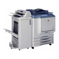
Konica Minolta CF5001 Service Manual (587 pages)
Konica Minolta CF5001 Laser MFP Service Manual
Brand:
Konica Minolta
| Category:
All in One Printer
| Size: 7.39 MB
Table of Contents
Service Manual
1
Table of Contents
3
Safety and Important Warning Items
13
Important Notice
13
Description Items for Danger, Warning and Caution
13
Safety Warnings
14
Safety Information
22
Important Information
22
Safety Circuits
23
Indication of Warning on the Machine
25
Safety and Important Warning Items
30
Idisassembly/Assembly
31
Exterior
31
Replacing the Dust Filter /2
31
Replacing the Dust Filter /1 and the Ozone Filter /1
32
Replacing the Toner Collection Box
34
Angle Adjustment of the Operation Board
36
Removing and Reinstalling the Main Board Unit
37
Scanner
41
Screws that Must Not be Removed
41
Removing and Reinstalling the Platen Glass
41
Removing and Reinstalling the CCD Unit
42
Removing and Reinstalling the Exposure Unit
44
Removing and Reinstalling the Exposure Lamp
47
Removing the Scanner Wire
48
Reinstalling the Scanner Wire
50
Writing
53
Screw that Must Not be Removed
53
Removing and Reinstalling the Write Unit
54
Process Unit
57
Flow of the Disassembly of the Process Unit Section
57
Cleaning the Charging Corona Unit
58
Cleaning/Replacing, Removing and Reinstalling the Charging Wire Assy /The Charging Control Plate
60
Pulling out the Process Unit
61
Removing and Reinstalling the Transfer Belt Unit
62
Replacing the Belt Cleaning Brush Unit
65
Replacing the Belt Cleaning Blade
66
Replacing the Toner Collection Sheet /1
67
Replacing the Belt Separation Claw
68
Replacing the Transfer Belt
69
Replacing the 1St Transfer Roller
71
Replacing the 2Nd Transfer Roller /U
72
Replacing the Drum Cartridge
73
Removing and Reinstalling the Drum
74
Replacing the Developing Unit
76
Replacing the Developer
78
Replacing the Belt Separation Claw Solenoid
80
Removing and Reinstalling the Process Unit
81
Removing and Reinstalling the Image Correction Unit
82
Toner Supply
83
Opening and Closing the Toner Supply Section
83
Replacing the Charging Dust Filter
84
PAPER FEED TRAYS /1 to /3
85
Removing and Reinstalling the Paper Feed Unit
85
Removing and Reinstalling the Paper Feed Trays /1 to /3
87
Replacing the Paper Feed Roller and the Feed Rubber
88
Replacing the Double Feed Prevention Rubber
90
Replacing the Paper Feed Clutch and the Pre-Registration Clutch
91
Removing and Reinstalling the Tray Up/Down Wire
92
By-Pass Tray
96
Replacing the Paper Feed Roller and the Feed Roller
96
Replacing the Double Feed Prevention Roller
98
Replacing the Paper Feed Clutch /BP
99
Vertical Conveyance
101
Removing and Reinstalling the Vertical Conveyance
101
Replacing the Intermediate Conveyance Clutch /1
104
Fixing
105
Screws that Must Not be Removed
105
Removing and Reinstalling the Fixing Unit
106
Replacing the Fixing Upper Heater Lamps /1 and /2
107
Replacing the Fixing Lower Heater Lamp
109
Replacing the Fixing Roller /U, Ball Bearing /U and the Heat Insulating Sleeve /U
112
Replacing the Fixing Roller /L, Ball Bearing /L and the Heat Insulating Sleeve /L
114
Replacing the Fixing Temperature Sensor /3, and Removing and Reinstalling
116
The Fixing Temperature Sensor /1 and the Thermostat /1
116
Replacing the Fixing Temperature Sensor /4, and Removing and Reinstalling
121
The Fixing Temperature Sensor /2 and the Thermostat /L
121
Replacing the Fixing Drive Gear
126
Replacing the Fixing Cleaning Unit
128
Replacing the Fixing Torque Limiter
130
Registration/Adu/Reverse/Paper Exit
132
Removing and Reinstalling the ADU
132
Replacing the Registration Cleaning Sheet
134
Replacing the Separation Discharging Plate Unit
135
Replacing the Transfer Ground Plate Unit and the 2Nd Transfer Roller /L
136
Replacing the Registration Roller
137
Replacing the Intermediate Conveyance Clutches /2 and /3
139
Replacing the ADU Conveyance Clutches /1 and /2
140
Replacing the ADU Pre-Registration Clutch
141
Replacing the Decurler Roller
142
Other
144
Installation of the Key Counter Socket (OPTION)
144
Installation / Remove of the Memory Unit (OPTION)
145
Disassembly/Assembly
147
Exterior
147
RADF Hinge Opening/Closing Angle Adjustment
147
Removing and Reinstalling the
149
Removing and Reinstalling the Rear Cover
150
Removing and Reinstalling the Registration Roller Cover
151
Paper Feed
152
Cleaning the no Paper Sensor
152
Removing and Reinstalling the Paper Feed Unit
153
Replacing the Paper Feed Roller and the Feed Roller
155
Replacing the Double Feed Prevention Roller
157
Paper Feed
159
Cleaning the Registration Roller
159
Cleaning the Registration Sensor
160
Removing and Reinstalling the Conveyance Belt
161
Reverse/Paper Exit
163
Cleaning the Paper Exit Roller/The Paper Exit Sensor
163
Cleaning the Reverse Roller
163
Removing and Reinstalling Radf
164
Disassembly/Assembly
165
Exterior
165
Removing and Reinstalling the
165
Removing and Reinstalling the Clutch Replacement Cover and the Rear Cover
167
Removing and Reinstalling the Paper Feed Pick-Up Cover
168
Paper Feed
169
Cleaning the Paper Dust Removing Brush
169
Removing and Reinstalling the Paper Feed Unit
170
Replacing the Paper Feed Roller and the Feed Roller
171
Replacing the Double Feed Prevention Roller
172
Replacing the Paper Feed Clutch and the Pre-Registration Clutch
174
Tray Up/Down
175
Removing and Reinstalling the Rear Drive
175
Removing and Reinstalling the Up/Down Wire
180
Fn-9/Fn120 Disassembly/Assembly
189
Exterior
189
Removing and Reinstalling of the Booklet Tray (FN-9 Only)
189
Removing and Reinstalling of the Top Cover /1
190
Removing and Reinstalling of the Top Cover /2
190
Removing and Reinstalling of the Side Cover
191
Removing and Reinstalling of the Finisher Door
191
Removing and Reinstalling of the Rear Cover
192
Removing and Reinstalling of the Main Tray
193
Removing and Reinstalling of the Main Paper Exit Opening Cover
194
Removing and Reinstalling of the Booklet Paper Exit Opening Cover (FN-9 Only)
194
Conveyance
195
Replacing the Paper Exit Roller /A (Sponge Roller)
195
Replacing the Intermediate Conveyance Roller (Sponge Roller)
197
Removing and Reinstalling of the Paper Exit Opening Unit
198
Main Tray
200
Replacing the Tray Up/Down Motor
200
Removing and Reinstalling of the Up/Down Wire
201
Stacker
205
Replacing the Stacking Assist Roller
205
Removing and Reinstalling of the Stacker Unit Cover
205
Removing and Reinstalling of the Stacker Unit
206
Stapler
209
Removing and Reinstalling of the Stapler Unit Cover
209
Replacing the Clincher
210
Replacing the Stapler
212
Disassembly/Assembly
215
Punch Section
215
Replacing the Punch Unit
215
Cleaning the Punch Edges and Punch Scraps Full PS (PS802)
218
Cover Inserter D DISASSEMBLY/ASSEMBLY
219
External Section
219
Removing / Re-Installing the External Covers
219
Paper Feed Unit
221
Replacing the Paper Feed Roller and Feed Roller
221
Replacing the Double Feed Prevent Roller and Torque Limiter
222
Disassembly/Assembly
223
Trimmer
223
Replacing the Trimmer Knife /U and Trimmer Knife /L
223
Adjustment
227
Adjustments When Replacing Parts
227
How to Use the Adjustment Section
227
Composition
227
List of Adjustment Items
228
Mode Change Menu
230
Setting Method
230
Display Transition of 36 Modes
231
Display Transition of 25 Modes
233
Display Transition of Key Operation Modes
234
Checking by the P Function
236
Checking Method of the P Function
236
Mode
237
List of Adjustment Items for 25 Mode
237
Setting Method
238
Setting Software DIPSW
238
Non-Standard Size Setting
251
Paper Size Setting
251
Standard Size Setting
251
Wide Paper Setting
251
Change Setting
252
Count Reset
252
PM Count Setting
252
Data Collection
253
Count of Special Parts
268
Parts Counter
268
Count of each Parts
273
Password Setting
274
Telephone Number Setting
274
Indication of ROM Version
275
Isw
275
M/C Serial Number Setting
275
Board Change Mode
276
Setting Date Input
276
Mode
277
Process Adjustment
277
Setting Method
277
Drum Peculiarity Adjustment
278
High Voltage Adjustment
278
Exclusive Paper Setting
284
Sensor Output Check
284
Recall Standard Data
285
Image Adjustment
286
Magnification Adjustment
286
Timing Adjustment
292
RADF Adjustment
300
Centring Adjustment
302
Non-Image Area Erase Check
305
Recall Standard Data
306
Image Quality Adjustment
307
Scanner Gamma Adjustment
307
Printer Gamma Adjustment
310
Sharpness Adjustment
313
Contrast Adjustment
314
Image Judge Adjustment
314
ACS Adjustment
316
Density Adjustment
317
Tone Adjustment
319
Recall Standard Data
320
Running Test Mode
321
Setting Method
321
Test Pattern Output Mode
322
Finisher Adjustment
326
Test Pattern Density Setting
326
Fold Stopper Adjustment (FN-9 Only)
327
Stitch and Fold Stopper Adjustment (FN-9 Only)
327
Cover Sheet Tray Size Adjustment (Cover Inserter D Only)
328
Trimming Stopper Adjustment (TMG-3 Only)
328
Punch Adjustment (PK-5 Only)
329
Three-Folding Adjustment (FN-9 Only)
331
List Output Mode
332
Positions Staple Pitch Adjustment
332
Mode
333
Mode/Multi Mode Setting Method
333
Adjustment Data Display
334
Hard Disk Check
334
Input Check List
335
Output Check List
347
Other Adjustments
357
Paper Feed Roller/Bp Pressure Adjustment
357
Paper Feed Height (Upper Limit) Adjustment (By-Pass)
358
Pick-Up Movement Amount Adjustment (By-Pass)
360
Paper Feed Tray /1 to /3 Mis-Centering Adjustment
361
Paper Feed Tray/1 to /3 Sheet Feed Pressure Adjustment
362
FNS Adjustment of the By-Pass Conveyance Guide Plate Magnet
364
FNS Adjustment of the By-Pass Gate
365
FNS Adjustment of the Shift Position
367
FNS Adjustment of the Paper Exit Opening Solenoid
368
FNS Adjustment of the Position of Paper Exit Arm
370
FNS Adjustment of the Position of Alignment Plate/U
372
FNS Adjustment of the Position of Alignment Plate/L (Only for FN-9)
374
FNS Adjustment of the Stapling Position (Flat Stapling)
376
FNS Adjustment of the Stapling Position in a Vertical Direction
378
FNS Adjustment of the Stapling Position (Flat Stapling) (Only for FN-9)
382
FNS Adjustment of the Angle of the Folding Stopper (Only for FN-9)
384
FNS Adjustment of the Folding Force (Only for FN-9)
386
FNS Adjustment of the Three-Holding Position (Only for FN-9)
387
FNS Adjustment of the Stapler Drive Belt Position
388
TU Adjustment of the Sheet Cutting Parallelism
392
LCT Tray Mis-Centering Adjustment
393
LCT Skew Adjustment
395
LCT Paper Feed Roller Pressure Adjustment
397
LCT Up/Down Plate Horizontal Adjustment
398
LCT Sheet Feed Pressure Adjustment
399
LCT Paper Feed Height (Upper Limit) Adjustment
400
LCT Pick-Up Release Amount Adjustment
402
PK Adjusting the Tilt of the Punch Hole Position
404
Sensitivity Adjustment for the PK Paper Edge Sensor
405
PI Centering Adjustment
406
Adjusting the Tilt of PI (When PK Punch Is Used)
407
Service Tool
409
3 III Service Tool
409
Isw
409
Description of the ISW
409
Installing the USB Driver for Iswtrns
409
Setup
410
Board Used for the ISW
410
Data Flow
410
ISW Transfer Type
410
Instances of ISW Transfer
411
Setup Procedure
412
UPDATING with ISW Trns
417
Setting up ISW Trns
417
Installing the Application Program
417
ISW Trns Main Window Overview
419
Parallel Port Setup
421
Copying Transfer Data (Update Data)
422
Connecting the CF5001
423
Updating
423
Update Operation Overview
423
Checking the ROM Version of the Copier (before Updating)
424
Preparing the Copier to Transfer
424
Running ISW Trns
424
Selecting Transfer File (Update Data) Conditions
424
Selecting a Version of Transfer Files (Update Data)
425
Transmitting Transfer Files (Update Data)
426
Verifying Transfer Files (Update Data)
426
Exiting ISW Trns
427
ISW Trns Messages
428
Troubleshooting ISW Trns
430
NG Produced by a File Check
430
Produced by a File Check
430
Send File Is Not Displayed When a Combo Box Item Is Selected
430
Unable to Run ISW Trns
430
Unsuccessful File Transfer
430
Connecting to the ISW Connector
430
Procedure
430
Internet Isw
431
What Is the Internet ISW
431
Operating Environment
431
Main Features
431
Initial Setting
432
Setting on Control Panel
432
Setting on Web Browser
432
Internet ISW Using E-Mail Remote Notification System
440
Function
440
Transmitting E-Mail
441
Internet ISW Using Web Utility
446
Function
446
How to Use
446
Precautions for Use
449
If ISW Fails in Low Power Mode
449
If Power Failure Occurs During Data Rewriting
449
ISW of Multiple Programs
449
Prior Announcement to Administrator
449
Proxy Server Authentication in Internet ISW
450
Authentication of Proxy Server
450
Type and Command List for Authentication on Proxy Server
450
What Is a Proxy Server
450
Remarks
451
Mail Remote Notification System
452
What Is the Mail Remote Notification System
452
Operation Environment
452
Initial Setting
452
How to Use the Mail Remote Notification System
461
Disabling System
467
Service
469
Service Schedule
469
Maintenance Items
471
Periodic Check Items (Main Body)
476
Periodic Check Items (AFR-20)
479
Periodic Check Items (C-208)
480
Periodic Check Items (FN-120/FN-9)
481
Periodic Check Items (Cover Inserter D)
482
Periodic Check Items (TMG-3)
482
Replacement Parts List
483
Important Maintenance Parts
486
Copy Material
487
Product
487
Materials
487
PM Parts Kit
488
Service Material List
489
Ce Tools List
490
Code List
491
Jam Code List
491
Error Code List
501
About Abnormal Unit Isolation
527
Diagrams
529
Parts Layout Drawing
529
CF5001 Parts Layout Drawing
529
Parts Layout Drawing
550
Parts Layout Drawing
551
FN-120/FN-9 Parts Layout Drawing
552
Parts Layout Drawing
556
Connector Layout Drawing
558
Main Body Connector Layout Drawing
558
Connector Layout Drawing
567
FN-120/FN-9 Connector Layout Drawing
568
Connector Layout Drawing
569
Timing Chart
570
Main Body Timing Chart
570
Timing Chart
572
Timing Chart
579
FN-120/FN-9 Timing Chart
580
Timing Chart
584
Advertisement
Konica Minolta CF5001 Service Manual (428 pages)
Brand:
Konica Minolta
| Category:
Printer
| Size: 25.06 MB
Table of Contents
Important Notice
3
Description Items for Danger, Warning and Caution
3
Iadjustment
33
How to Use the Adjustment Section
33
Composition
33
Adjustments When Replacing Parts
33
List of Adjustment Items
34
Mode Change Menu
36
Setting Method
36
Checking by the P Function
36
Checking Method of the P Function
36
Mode
37
List of Adjustment Items for 25 Mode
37
Setting Method
38
Setting Software DIPSW
38
Paper Size Setting
54
Standard Size Setting
54
Non-Standard Size Setting
54
Wide Paper Setting
54
PM Count Setting
55
Count Reset
55
Change Setting
55
Data Collection
56
Parts Counter
72
Count of Special Parts
72
Count of each Parts
79
Password Setting
81
Telephone Number Setting
81
M/C Serial Number Setting
82
Indication of ROM Version
82
KRDS Setting
82
Isw
82
Setting Date Input
83
Board Change Mode
83
Mode
84
Setting Method
84
Process Adjustment
84
High Voltage Adjustment
85
Drum Peculiarity Adjustment
85
Sensor Output Check
91
Exclusive Paper Setting
91
Recall Standard Data
93
Image Adjustment
94
Magnification Adjustment
94
Timing Adjustment
100
RADF Adjustment
108
Centring Adjustment
110
Non-Image Area Erase Check
112
Recall Standard Data
113
Image Quality Adjustment
114
Scanner Gamma Adjustment
114
Printer Gamma Adjustment
117
Sharpness Adjustment
120
Contrast Adjustment
121
Image Judge Adjustment
121
ACS Adjustment
123
Density Adjustment
124
Tone Adjustment
126
Recall Standard Data
127
Running Test Mode
128
Setting Method
128
Test Pattern Output Mode
129
Test Pattern Density Setting
138
Finisher Adjustment
138
Stitch and Fold Stopper Adjustment (FS-215/FN-9/FS-606 Only)
139
Fold Stopper Adjustment (FS-215/FN-9/FS-606 Only)
139
Cover Sheet Tray Size Adjustment (PI-110 Only)
140
Trimming Stopper Adjustment (TU-109/TMG-3 Only)
140
Punch Adjustment (PK-120/PK-5/PK-507 Only)
141
Three-Folding Adjustment (FS-215/FN-9/FS-606 Only)
143
Positions Staple Pitch Adjustment
144
List Output Mode
144
Mode
145
Mode/Multi Mode Setting Method
145
Adjustment Data Display
146
Hard Disk Check
146
Input Check List
148
Output Check List
159
Other Adjustments
171
Paper Feed Roller/Bp Pressure Adjustment
171
Paper Feed Height (Upper Limit) Adjustment (Bypass)
172
Pick-Up Movement Amount Adjustment (Bypass)
174
Paper Feed Tray /1 to /3 Mis-Centering Adjustment
175
Paper Feed Tray/1 to /3 Sheet Feed Pressure Adjustment
176
FNS Adjustment of the Bypass Conveyance Guide Plate Magnet
178
FNS Adjustment of the Bypass Gate
179
FNS Adjustment of the Shift Position
181
FNS Adjustment of the Paper Exit Opening Solenoid
182
FNS Adjustment of the Position of Paper Exit Arm
184
FNS Adjustment of the Position of Alignment Plate /U
186
FNS Adjustment of the Position of Alignment Plate /L (Only for FS-215/FN-9/FS-606)
188
FNS Adjustment of the Stapling Position (Flat Stapling)
200
FNS Adjustment of the Stapling Position (Flat Stapling) (Only for FS-215/FN-9/FS-606)
200
FNS Adjustment of the Angle of the Folding Stopper (Only for FS-215/FN-9/FS-606)
202
FNS Adjustment of the Folding Force (Only for FS-215/FN-9/FS-606)
204
FNS Adjustment of the Three-Holding Position (Only for FS-215/FN-9/FS-606)
205
FNS Adjustment of the Stapler Drive Belt Position
206
TU Adjustment of the Sheet Cutting Parallelism
210
LCT Tray Mis-Centering Adjustment
211
LCT Skew Adjustment
213
LCT Paper Feed Roller Pressure Adjustment
215
LCT Up/Down Plate Horizontal Adjustment
216
LCT Sheet Feed Pressure Adjustment
217
LCT Paper Feed Height (Upper Limit) Adjustment
218
LCT Pick-Up Release Amount Adjustment
220
Service Tool
223
2 II Service Tool
223
Description of the ISW
223
Setup
223
Board Used for the ISW
223
Data Flow
223
ISW Transfer Type
223
Instances of ISW Transfer
225
Setup Procedure
226
Usb Isw
231
What Is the USB ISW
231
Internet Isw
233
What Is the Internet ISW
233
Operating Environment
233
Main Features
233
Initial Setting
234
Setting on Control Panel
234
Setting on Web Browser
234
Internet ISW Using E-Mail Remote Notification System
242
Function
242
Transmitting E-Mail
243
Internet ISW Using Web Utility
248
Function
248
How to Use
248
Precautions for Use
251
Prior Announcement to Administrator
251
If Power Failure Occurs During Data Rewriting
251
ISW of Multiple Programs
251
If ISW Fails in Low Power Mode
251
Proxy Server Authentication in Internet ISW
252
What Is a Proxy Server
252
Authentication of Proxy Server
252
Type and Command List for Authentication on Proxy Server
252
Remarks
253
Mail Remote Notification System
254
What Is the Mail Remote Notification System
254
Operation Environment
254
Initial Setting
254
How to Use the Mail Remote Notification System
261
Disabling System
269
Service
271
Service Schedule
271
Maintenance Items
273
Periodic Check Items (Main Body)
278
Periodic Check Items (DF-319/AFR-20)
282
Periodic Check Items (LT-211/C-208)
282
Periodic Check Items (FS-115/215/FN-120/9/FS-513/606)
283
Periodic Check Items (PI-110)
284
Periodic Check Items (TU-109/TMG-3)
284
Replacement Parts List
285
Important Maintenance Parts
289
Copy Material
290
Product
290
Materials
290
PM Parts Kit
291
Service Material List
293
Ce Tools List
294
Jam Code List
295
Error Code List
305
About Abnormal Unit Isolation
333
Diagrams
335
Parts Layout Drawing
335
8050/CF5001/C500/8150 Parts Layout Drawing
335
DF-319/AFR-20 Parts Layout Drawing
356
LT-211/C-208 Parts Layout Drawing
357
FS-115/FS-215/FN-120/FN-9/FS-513/FS-606 Parts Layout Drawing
358
TU-109/TMG-3 Parts Layout Drawing
362
PK-120/PK-5/PK-507 Parts Layout Drawing
364
Connector Layout Drawing
365
8050/CF5001/C500/8150 Connector Layout Drawing
365
Relay Connector
365
Connector in the Board
373
DF-319/AFR-20 Connector Layout Drawing
383
LT-211/C-208 Connector Layout Drawing
384
FS-115/FS-215/FN-120/FN-9/FS-513/FS-606 Connector Layout Drawing
385
TU-109/TMG-3 Connector Layout Drawing
386
PK-120/PK-5/PK-507 Connector Layout Drawing
386
Timing Chart
387
8050/CF5001/C500/8150 Timing Chart
387
DF-319/AFR-20 Timing Chart
388
LT-211/C-208 Timing Chart
395
FS-115/215/FN-120/9/FS-513/606 Timing Chart
396
TU-109/TMG-3 Timing Chart
400
PK-120/PK-5/PK-507 Timing Chart
402
Overall Wiring Diagram
403
Overall Wiring Diagram
404
LT-211/C-208 Overall Wiring Diagram
405
FS-115/215/FN-120/9/FS-513/606 Overall Wiring Diagram
407
TU-109/TMG-3 Overall Wiring Diagram
409
PK-120/PK-5/PK-507 Overall Wiring Diagram
411
Appendix
413
8050/CF5001/C500/8150 Overall Wiring Diagram (1/8)
413
8050/CF5001/C500/8150 Overall Wiring Diagram (2/8)
413
8050/CF5001/C500/8150 Overall Wiring Diagram (3/8)
415
8050/CF5001/C500/8150 Overall Wiring Diagram (4/8)
417
8050/CF5001/C500/8150 Overall Wiring Diagram (5/8)
419
8050/CF5001/C500/8150 Overall Wiring Diagram (6/8)
421
Fixing Unit
425
Konica Minolta CF5001 Service Manual (130 pages)
Brand:
Konica Minolta
| Category:
All in One Printer
| Size: 2.43 MB
Table of Contents
Service Manual
1
Table of Contents
2
Safety and Important Warning Items
6
Important Notice
6
Description Items for Danger, Warning and Caution
6
Safety Warnings
7
Safety Information
15
Important Information
15
Safety Circuits
16
Indication of Warning on the Machine
18
Safety and Important Warning Items
23
Ioutline
24
Outline of System
24
Product Specifications
25
Center Cross Section
28
Paper Path
29
Drive System Diagram
31
Drum Drive
31
Transfer Belt Conveyance/Pressure Drive
32
Developing Drive
33
Toner Supply Drive
34
Toner Collection Drive
35
Fixing Drive
36
Paper Feed Drive
37
Paper Feed Tray /1 to /3 Drive
37
Vertical Conveyance Drive
38
ADU Drive
39
By-Pass Tray Drive
39
Registration Drive/Loop Drive
40
ADU Conveyance Drive
41
Reverse Paper Exit Drive
42
Main Body Paper Exit Drive
43
Scanner Drive
44
Image Creation Process
45
Image Creation Flow and Function
45
Charging Process (Step 1)
46
Laser Exposure Process (Step 2)
46
Developing Process (Step 3)
47
1St Transfer Process (Step 4)
48
2Nd Transfer Process (Step 5)
49
Separation Process (Step 6)
49
Drum Cleaning (Sub Step 1)
50
Pre-Charging Exposure (Sub Step 2)
50
Transfer Belt Cleaning (Sub Step 3)
51
2Nd Transfer Roller /L Cleaning (Sub Step 4)
51
Toner Collection (Sub Step 5)
52
Process Speed
52
Unit Explanation
54
Scanner
54
Composition
54
Operation
55
Home Position Search in the Exposure Unit
55
Shading Correction Reading
56
Original Reading Mode
57
Original Reading Control
58
APS Control
61
AE Control
62
Image Processing
62
Write
64
Composition
64
Operation
66
Image Writing
66
Color Registration Correction Control
66
Drum Unit
72
Composition
72
Operation
76
Image Formation Timing
76
Developing Unit
77
Composition
77
Operation
79
Flow of Developer
79
Developing Control
79
Toner Supply Control to the Developing Unit
79
Developing Bias Control
80
Durability of the Developer
80
Transfer Belt Unit
81
Composition
81
Operation
83
Transfer Belt Pressure/Release Mechanism
83
Image Correction Unit
84
1St Transfer Control
85
2Nd Transfer Control
85
Toner Supply
86
Composition
86
Operation
87
Toner Supply Control to the Toner Hopper Section
87
Toner Supply Control to the Developing Unit
87
Copy/Print Operation Stop Control Due to no Toner
88
Toner Collection
89
Composition
89
Operation
90
Toner Collection Control
90
Waste Toner Full Detection Control
90
Paper Feed Tray /1 to /3
91
Composition
91
Operation
93
Paper Feed Control
93
Up/Down Plate Control
94
Remaining Paper Detection Control
94
Paper Size Detection Control
95
By-Pass Feed
96
Composition
96
Operation
97
Tray up Drive Control
97
Paper Feed Control
97
Paper Size Detection Control
97
Vertical Conveyance
98
Composition
98
Operation
98
Vertical Conveyance Control
98
Registration/Adu/Reverse/Paper Exit
99
Composition
99
Operation
102
Switching Control of the Paper Exit/Adu Conveyance Path
102
Reverse/Exit Control
106
ADU Conveyance Control
107
Paper Reverse Control
108
ADU Pre-Registration Control
110
Registration Control
111
2Nd Transfer Control
112
Paper Exit Full Detection Control
112
Fixing Unit
113
Composition
113
Operation
115
Fixing Drive Control
115
Pressure/Release Control
116
Web Control
117
Temperature Control
117
Interface
118
Composition
118
Image Stabilization Control
119
Toner Density Control
119
Dmax Control
119
Charging Potential Control
120
Correction of the Reference Value
120
Low Humidity Environment Correction
120
Dot Diameter Adjustment Control
121
Gamma Correction Control
121
Other Controls
122
Parts to Which Power Is Supplied Even When the Reset Switch Is Turned off
122
Parts that Operate Only When the Power Switch Is Turned on
123
Parts that Operate When the Reset Switch Is Turned on
123
Parts that Operate When the Main Switch Is Turned on
123
Fan Control
124
Fan Composition
124
Operation Board Control
125
Operation Board Composition
125
Counter Control
126
Counter Composition
126
Counter Operation
126
ACS Control
128
Switching between the Color Mode and the Black and White Mode
128
Copy Count When Using ACS
128
Advertisement
Advertisement
Related Products
Konica Minolta BIZHUB C450P
Konica Minolta bizhub press c1070p
Konica Minolta bizhub press c1060
Konica Minolta bizhub C308
Konica Minolta bizhub C3350i
Konica Minolta bizhub C764
Konica Minolta Bizhub C659
Konica Minolta bizhub C287
Konica Minolta bizhub C650 Series
Konica Minolta BIZHUB C351
Konica Minolta Categories
All in One Printer
Printer
Digital Camera
Measuring Instruments
Copier
More Konica Minolta Manuals
Login
Sign In
OR
Sign in with Facebook
Sign in with Google
Upload manual
Upload from disk
Upload from URL