Invacare STORM Service Manual
Hide thumbs
Also See for STORM:
- User manual (127 pages) ,
- User manual (156 pages) ,
- Service manual (125 pages)

Related Manuals for Invacare STORM


Summary of Contents for Invacare STORM
- Page 1 STORM S S E E R R V V I I C C E E M M A A N N U U A A L L This manual includes: • Information on troubleshooting • Information on testing parts • Repair instructions F392044 Edition 01.99...
-
Page 2: General Information
• Should you encounter difficulties or have any questions, please contact INVACARE-SERVICE: • INVACARE can not be held liable for changes to the STORM resulting from maintenance and servicing work carried out incorrectly or not according to the relevant instructions. -
Page 3: Table Of Contents
Table of Contents Chapter Page Chapter Page Legrests with 73 and 90 degree Safety and Assembly Instructions ..5 angle adjustment ....28 Legrests with manual List of Tools . - Page 4 Table of Contents Chapter Page Chapter Page 12.0 Check and Repair Work 17.0 Repair Work on the Driving Electronics on Electrical System ....66 (Replacing Modules) ....92 12.1 Checking batteries, battery boxes and 17.1...
-
Page 5: Safety And Assembly Instructions
1.0 Safety and assembly instructions The safety instructions are provided in the interests of working safety and must under all circumstances be complied with. Prior to all inspection and repair work: • Read this service manual and the appertaining User’s Manual. •... -
Page 6: List Of Tools
2.0 List of tools A standard toolkit comprising the following minimum inventory is required: Combination ring and open-end spanner SW 6, 7, 8, 10, 11, 12, 13, 17, 19 Allan key 2,5 mm, 3mm, 4mm, 5 mm, 6 mm, 8mm, 10mm Torque wrench (commercially available) Socket spanner set... -
Page 7: Arrangement Of Subassemblies, Components
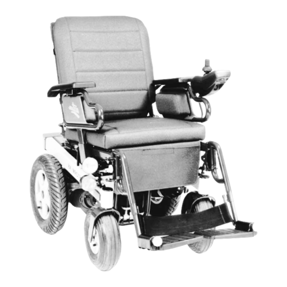
The following illustrations depict the general arrangement of the wheelchair’s subassemblies, components and operational controls. The designations correspond to the designations of the components listed in the spare-parts catalogue. Basically, the STORM is available as models Standard, Comfort and Recaro, each one consisting of the following main subassemblies.: • Chassis •... - Page 8 Storm Comfort with headrest and 1 Headrest, complete electric backrests plus seat 2 Back frame tube adjustment, view from the left 3 Actuator for backrest 4 Brake lever for parking brake 5 Side part, complete 6 Actuator for seat 7 Legrest, complete...
- Page 9 Storm Recaro, View from the right 1 Recaro seat, complete 2 Side part, complete 3 Mounting kit for joystick box, swiveling 4 Special joystick box 5 Legrests, complete 6 Foot plates 7 Kerbstone lifter, complete 8 Front wheel, complete 9 Reflector...
-
Page 10: Components Of The Electronic
4.0 Components of the Electronic Control (ACS) 4.1 General The wheelchair’s electronic control (Action Control System = ACS) Lighting Module Main Module consists of individual components (modules). According to each type of wheelchair, the wheelchairs are equipped with different modules. ACS Modules: Standard Joystick Box Designation of Module... -
Page 11: Status Display (Error Display)
The ACS is equipped with an error memory, which can be evaluated by means of a commercially available PC. The additionally required hard and software can be ordered from INVACARE Deutschland GmbH under Part No..: P10 076. 4.4 Microswitch Mikroswitch The microswitch is only mounted in connection with lighting module 12 V (TÜV version). -
Page 12: Modules
For a joystick box, any model can be used that is no older than the Module and Cable Equipment original joystick box. INVACARE joystick boxes are backward but not forward compatible. Modules for the wheelchair lighting or for the actuators for the adjustment of the seat and legrest angles can be installed additionally. -
Page 13: With Lighting 24 V, With Actuators
Wheelchair Equipment : with Lighting 24 V, with Actuators Module and Cable Equipment Modules • Main module (Power Module) to control unit • Lighting / Adjustment module Power Module Lighting/Actuator (Combined lighting + actuator module) Module • Joystick box • Control of actuators (With older joystick boxes adjustment options cannot be controlled via the the joystick box.) Cables... -
Page 14: With Lighting 12 V, With Actuators
Wheelchair Equipment: with 12 V Lighting (TÜV version), with Actuators Module and Cable Equipment Lighting/Actuator 12 V Lighting Module Main Moduleer Modules: • Main module (power module) Module • Lighting / actuator module (combined lighting + actuator module) Control Unit Joystick Box •... -
Page 15: Inspection Plan
6.0 Inspection Plan Assembly Check Remedy Chapter • Headrest shell and > Replace in case of Headrest padding damage • Headrest holder and > Tighten screws, fastenings Replace parts • Damage and fastening > Tighten screws, replace Armrests of armrests •... - Page 16 Assembly Check Remedy Chapter • Function > Adjust, replace Parking Brake • Bowden wires loose, Bowden wire covering damaged > Tighten, adjust, replace 14.4 • Wear, damage of brake drums and brake linings > Replace • Check functions for driving >...
-
Page 17: Operation Troubles
7.0 Operation Troubles 7.1 General Note In case of malfunctions of the lighting system, actuators or power supply, proceed as follows: • First evaluate the causes of malfunction specified in chapter 7.2. • Check status display on joystick box and evalute the error codes according to chapter 8.1, if necessary. •... - Page 18 An actuator reacting irregularly or not at all Motor or adjustment Check flashing code Chapter 8.0 module defective on joystick box No flashing code? Replace actuator Chapter 14.3 Actuator defective Servo/lighting module Replace servo/lighting Chapter 17.7 defective module Joystick box defective Replace joystick box Chapter 17.1 - 17.5 Adjustment control...
-
Page 19: Error Messages On Joystick Box
8.0 Error Messages on Joystick Box 8.1 Error Codes of Joystick Box The error codes specified as follows refer to the different STORM versions. Perform the following test before evaluating error codes: • Switch joystick box repeatedly off and on again. Wait approx. 5 seconds each time before switching on again. - Page 20 Check battery charger 9 x Flashing Error in data transfer Check modules and programming, Chapter 19.0 between modules inform INVACARE Service 10x Flashing Check plug and socket Chapter 18.0 connections plus BUS cable Only in 10 km/h TÜV version: *...
-
Page 21: Check And Repair Work On The Standard Seat System
9.0 Testing and Repair Work on the Standard Seat System Headrest Headrest, disassembled Headrest, assembled 1 Headrest, complete 2 Headrest support 3 Headrest arm 4 Headrest arm bracket 5 Headrest shell 6 Headrest pad 7 Hexagon head screw M8x50 8 2x Bushing 8,5x13 9 2x Washer 8,5 10 2x Slotted head screw M4x15 11 Nut M8, self-locking... -
Page 22: Armrests And Sides
Armrests and Side Parts Side part, disassembled Side part, disassembled 1 Side part, complete 2 Side frame 3 Armrest pad 4 Side panel 5 Side pads 6 Hexagonal screw M4x35 7 Wing or Allen screw M5 8 Side part holder 9 Clamping lever M8x60 10 Crossbeam, (part of the seat frame) 11 Clamping lever M8x60 12 2x Bore hole for compression rivets... -
Page 23: Legrests With One-Piece Foot Plate
Legrests with Single Footboard. Legrests, Legrests, disassembled assembled 1 Legrests, complete 2 Legrest upper part, left 3 Insert tube 18,5 mm, right (locked in the footboard) 4 Insert tube 18,5 mm, left 5 Sport footboard (ALU) 6 Rubber mat, glued 7 Calf belt 8 Clamp 22 mm 9 Button-headed screw M8x25... -
Page 24: Legrests With One-Piece Foot Plate For Short Lower Legs
Legrest with One Piece Footboard for Short Lower Legs Legrest receptacle, left Legrest, disassembled 1 Legrest receptacle 2 Seat frame 3 Hinge bolt 7,8x30 mm 4 Hinge bolt 7,8x35 mm 5 Legrest lock, spring-weighed 6 Legrest upper part 7 Sliding tube 8 Insert tube 9 Footrest receptacle 10 Width compensation... - Page 25 Disassembly, complete The following steps apply to both legrests! • Remove calf belt (33) from footboard receptacle (9). • Grasp footboard (11) by its left side and turn upwards until it is released from the left footboard receptacle (9). • Release legrest lock (5) and lift legrest from the hinge bolts (3 and 4). •...
-
Page 26: Standard Legrests And Standard Legrests With Angle Adjustment
Standard Legrests and Standard Legrests with Angle Adjustment Legrest, Legrest receptacle, left disassembled 1 Legrest receptacle 2 Seat frame 3 Hinge bolt 7,8x30 mm 4 Hinge bolt 7,8x35 mm 5 Legrest lock, 6 Legrest upper part spring-weighed 7 Slide piece SL22 8 Legrest lower part 9 Screw M8x10 10 Footplate, large... - Page 27 Disassembly of Standard Legrests (complete) • Detach calf belt (13) from legrest lower part (8). • Release legrest lock (5) and lift legrest from hinge bolts (3 and 4). • Loosen screw (9) and pull legrest upper part (6) from legrest lower part (8). •...
-
Page 28: Legrests With 73 And 90 Degree Angle Adjustment
Legrests, 73 and 90 degrees, angle adjustable Legrest receptacle, left Legrest, disassembled 1 Legrest receptacle 2 Seat frame 3 Hinge bolt 7,8x30 mm 4 Hinge bolt 7,8x35 mm 5 Legrest lock, 6 Legrest upper part spring-weighed 7 Insert tube, conical 8 Legrest lower part 9 Footplate tube 10 Footplate, small... - Page 29 Disassembly (complete) • Detach calf belt (20) from insert tube (7). • Release legrest lock (5) and lift legrest from hinge bolts (3 and 4). • Loosen screw (17) and pull legrest upper part (6) from the insert tube (7). •...
-
Page 30: Legrests With Manual Height Adjustment
Legrests, manually height adjustable Legrest receptacle, left Legrest, disassembled 1 Legrest receptacle 2 Seat frame 3 Hinge bolt 7,8x30 mm 4 Hinge bolt 7,8x35 mm 5 Legrest lock, 6 Legrest upper partl spring-weighed 7 3x slide piece SL22 8 Slide piece Y13x4x8 9 Legrest elbow tube 10 Bushing RD 18x6x22 11 Screw M6x35... - Page 31 Disassembly (complete) • Release legrest lock (5) and lift legrest from the hinge bolts (3 and 4). • Loosen nut (20) and pull insert tube (21), together with footplate tube (22) and footplate (23), from legrest elbow tube (9). • Loosen screw (25) with washers (26) and nut (27) completely and separate insert tube (21) from footplate tube (22).
- Page 32 Assembly NOTE: • The assembly is performed in the reverse order. • When assembling, always use new starlock caps (16). • During the assembly, attention is to be paid to the correct location of the parts (left, right). • Adjust legrests to equal length. •...
-
Page 33: Legrests With Electrical Height Adjustment
Legrests with electrical height adjustment Legrest, disassembled Legrest receptacle, left 28 29 Actuator motor, assembled 1 Legrest receptacle 2 Seat frame 3 Hinge bolt 7,8x30 mm 4 Hinge bolt 7,8x35 mm 5 Legrest locking, 6 Legrest upper part 7 Slide piece F 30x15 8 2x Washer 20x7,9x1 9 Joint plate 10 Joint plate... - Page 34 Disassembly (complete) • Remove connection plug (42) from the socket (in front, at lower part of battery holder). • Remove caps (31) from screws (30). • Loosen screws (30) at legrest upper part (6) and at legrest elbow tube (14) and detach the actuator (27) with bushings (28) and washers (29) completely.
-
Page 35: Anatomical Backrest Element In Standard And Comfort Version
Back Element, anatomical, in Standard and Comfort versions Back element, assembled Back element, disassembled NOTE: The back element can be equipped with back padding (1) or with back belting (3). 1 Back padding, anatomical 2 Tapping screw with cap 3 Back belting 4 Tapping screw with cap 5 Back frame tube 6 Back element holder... -
Page 36: Backrest Element Electrically Adjustable In Standard And Comfort Version
9.10 Back Element electrically adjustable in versions Standard and Comfort Back element, assembled Back element, disassembled 1 Back padding 2 8x Counters.tapp.screw 4,8x17 3 4x Clamping piece 4 Back belting 5 4x Counters.tapp. screw w/cap 6 Back frame tube 7 2 Hexagon head screw M8x45 8 2x Washer 16x8,3x1,5 9 2x Bushing 12x8,5x23 10 4x Washer 24x8,3x2... - Page 37 Disassembly complete • If existing, then remove the headrest first. See chapter 9.1 in this respect. • Remove connection plug (17) from the socket (in front, on the lower part of battery holder). • Remove quick-release bolt (12) on the upper part of the back frame tube (6) and put the actuator aside. •...
-
Page 38: Backrest Element Manually Adjustable In Standard And Comfort Quality
9.11 Back Element, Manually Adjustable, in Standard and Comfort Versions Back element, disassembled 1 Back padding 2 8x Counters.tapp.screw 4,8x17 3 4x Clamping piece 4 Back belting 5 4x Tapping screw with cap 6 Back frame tube 7 2x Hexagon head screws M8x45 8 2x Washer 16x8,3x1,5 9 2x Bushing 12x8,5x23 10 4x Washers 24x8,3x2... - Page 39 Disassembly, complete NOTE: • It is not absolutely necessary to follow each and every operational step indicated here. The compression spring and the Bowden wire, for instance, can be mounted or dismounted without having first to remove the entire backframe. •...
-
Page 40: Seat Cushion, Apron With Pocket And Seat Plate
9.12 Seat cushion, apron with pocket, and seat plate Storm Comfort, complete Seat plate, mounted Seat plate from below (lifted) 1 Seat cushion 2 Apron with pocket 3 Seat plate 4 Velcro fastener strips, glued 5 4x Tapping screw 4,8x18... -
Page 41: Wedge Cushion, Complete
9.13 Wedge cushion, complete Wedge cushion, disassembled 1 Wedge cushion holder 2 Insert tube A 3 Insert tube B 4 Insert tube C 5 Wedge cushion 6 3x Wing screws M6x10 7 6x Screws I I n n s s p p e e c c t t i i o o n n R R e e m m e e d d y y •... -
Page 42: Seat Frame, Complete
9.14 Seat frame, complete Storm Comfort with seat frame, assembled Legrest receptacle, left Seat frame, disassembled NOTE: For the seat recline adjustment, also an actuator can be installed. 1 Seat frame 2 2x Mounting plate 3 2x Hinge bolt 7,8x30... - Page 43 I I n n s s p p e e c c t t i i o o n n R R e e m m e e d d y y • Legrest locking tight or defective? > Smoothen or replace locking device. •...
- Page 44 Disassembly Seat Recline Adjustment, complete • Only in electrical legrest adjustment: Remove connection plugs from the sockets (in front, below) at the battery box retainer (28). • Release legrest locking device (30) and detach legrests (31). • Release quick-release bolt (24) above at the seat recline adjustment (19) or at the actuator (29) and remove together with washers (23), if necessary.
-
Page 45: Check And Repair Work On
10.0 Check and Repair Work on the Recaro Seating System 10.1 General Chapter 10 and its sub-chapters are dedicated to the description of the special features of the Recaro seating system. As to the disassembly / assembly of the legrests, the steps described in chapter 9 for the standard seating system are applicable. -
Page 46: Armrests And Sides
10.3 Armrests and side parts Side parts, assembled Side part, disassembled 1 Armrest holder 2 Clamping lever 3 Slide piece 4 Armrest receptacle 5 Wing screw 6 Receiver of armrest pad 7 2x Screws 8 Side part pocket 9 Armrest pad 10 Adapter 11 Wing / Allen screws 12 Mirror... -
Page 47: Seat Module And Seat Frame
10.4 Seat module and seat frame Seat Module LX, Seat Model DS NOTE: For the seat recline adjustment, also a manual adjustment device can be mounted. Recaro Seat, disassembled Seat module LX 14 2x Screws M8x50 27 2x Washer 16x8,4x1,5 Back module LX 15 2x Washer 16x8,3x1,5 28 Lock nut M8... - Page 48 I I n n s s p p e e c c t t i i o o n n R R e e m m e e d d y y • Padding damaged? > Replace Recaro seat. • Adjustment functions for Recaro seat module >...
- Page 49 Disassembly, seat recline adjustment complete • Only for electrical legrest adjustment: Remove connection plug from the sockets (front, below) at the battery box retainer. • Release legrest lock and detach legrests. • Release quick-release bolt (29) at the upper part of the seat recline adjustment device (not shown) or at actuator (21), and remove, if appropriate, together with washers.
-
Page 50: Check And Repair Work On Chassis
11.0 Check and Repair Work on the Chassis 11.1 Front wheel suspension and wheels 3.00-4” Front wheels, assembled Front wheels, disassembled NOTE: The front wheels can be equipped with 1-piece or 2-piece rims. 1 Chassis 2 Front wheel fork f/wheel 3.00-4” 3 Slide piece DA=42 4 Hexag. - Page 51 Disassembly, Front Wheels • Use suitable support (e.g. wooden block) and jack up wheelchair. • Hold axle bolt (13 or 14) with a jaw spanner (SW 13) and loosen 2 screws (16) completely. • Pull out axle bolt (13 or 14) and detach together with bushing (18 or 20) from the front wheel (7). •...
- Page 52 Disassembly, 2-piece rims and tyres • Remove front wheel (7) completely. See in this respect Disassembly / Assembly Front Wheels. • Remove valve cap (23) and deflate tyre by pressing the spring pin of the valve. • Unscrew 5 cheese-head screws (21) cross wise and detach from rims (11 and 12). •...
-
Page 53: Front Wheel Suspension And Wheels 200X50
11.2 Front Wheel Suspension and 200x50 Wheels Front wheels, assembled Front wheels, disassembled NOTE: The front wheels can be equipped with 1-piece or 2-piece rims. 1 Chassis 2 Front wheel fork f.wheel 200x50 3 Slide piece DA=42 4 Hex. head nut M12x1,5 Stop 5 Washer 13x24x2,5 6 Adjusting washer 16x22x1,0 7 Front wheel... - Page 54 Disassembly, 1-piece rims and tyres • Remove front wheel (7) completely. See in this respect Disassembly / Assembly Front Wheels. • Remove valve cap (not shown) and deflate tyre by pressing on the spring pin of the valve. • Pull outer cover (8) sideways from the rim(10) with the aid of a tyre puller. •...
-
Page 55: Rear Wheels And Tyres
11.3 Rear wheels and tyres Rear wheels, assembled Rear wheel, disassembled 1 Chassis 2 Drive, complete 3 Rear wheel 3.00-8” 4 Rim 1,5x8 (rim body outside) 5 Rim 1,5x8 (rim body inside) 6 Outer cover 3.00-8” 7 Inner tube 3.00-8” 8 4x Countersunk screw M8x20 PB 9 Wheel hub, standard 10 Wheel hub with brake drum... -
Page 56: Parking Brake And Wheel Hubs
11.4 Parking Brake and Wheel Hubs Parking brake, assembled Brake lever, assembled 31 / 32 Brake lever, disassembled Parking brake, disassembled 1 Brake lever, complete 2 Cover for brake housing 3 Plastic knob 4 4x Adjusting screw M6x24 5 2x Tapping screw 4,8x16 6 Bowden wire cover 530 mm 7 Bowden wire covering 830 mm 8 Inner brake cable 2000 mm... - Page 57 Disassembly Bowden Cable, complete NOTE: • Lift seating system and lock, if required. • It is recommended to remove the • Remove rear wheels (33). See chapter 11.3 in this respect. batteries before disassembling, in order • Release brake and write down the positions of the adjusting to reduce the weight of the wheelchair.
- Page 58 Disassembly brake housing with brake lever, complete. • Disassemble Bowden cable completey. See disassembly Bowden cable. • Loosen counter nuts and remove adjusting screws (4) at brake housing (10 and 11). • Loosen tapping screws (5) completely and detach brake housing from its holder (14). •...
-
Page 59: Rear Wheel Suspension With Shock Absorbers, Support Castors, Support Plates And Rear Wheel Link
11.5 Wheel Suspension in the Rear with Shock Absorbers, Support Castors, Support Plates and Rear Wheel Link Wheel suspension, disassembled 1 Chassis 2 Drive unit, complete 3 Support plate, short 4 Support castor 5 Shock absorber 6 Screw M8x50 7 Washer 8,4x25x2 8 Bushing RD 22x12, ALU 9 4x Screw M8x75 10 4x Lock nut M8... - Page 60 Disassembly support plates • Remove rear battery box and jack up wheelchair, if appropriate. • If required, remove rear wheel. See chapter 11.3 in this respect. • Loosen screw (9) and nut (10) at the lower part of the support plate (3) completely. •...
-
Page 61: Drive Unit, Complete
11.6 Driving Unit, complete Driving unit, disassembled Driving unit, assembled 11/12 1 Chassis 2 Driving unit, complete 3 Rear wheel link 4 Gear 5 Drive motor 6 Connection plug 7 2x Screw M6x30 8 4x Screw M6x30 and washer 9 Bowden cable holder 10 Wheel hub 11 Lock nut M12x1,5 12 Disc 13... -
Page 62: Splash Guard For Modules And Battery Box Retainer
11.7 Splash Protection for Modules and Battery Box Retainer Battery box retainer, assembled Battery box retainer, disassembled 1 Battery box retainer 2 2x Screw M8x20 3 6x Washer 16x8,4x1,5 4 2x Screw M8x35 5 2x Nut M8 Stop 6 Splash protection 7 2x Tapping screw 3,8x10 8 2x Screw M3x27 9 2x Nut M3 Stop... -
Page 63: Kerbstone Lifter
11.8 Kerbstone Lifter Kerbstone lifter, assembled Kerbstone lifter, disassembled 1 Chassis 2 Kerbstone lifter support 3 4x Screw M8x20 4 4x Washer 5 Compression spring 6 2x Screw 7 4x Washer 8 2x Lock nut 9 Kerbstone-lifter fork 10 2x Stopper 11 Screw 12 Washer 13 2x Bushing... -
Page 64: Transport Bracket, Taxi Bracket, Cane Holder And Reflectors
11.9 Transport Bracket, Taxi Bracket, Cane Holder and Reflectors View from the right Accessories, disassembled 1 Chassis 2 Cane holder 3 Angle 4 Screw and nut 5 2x Taxi bracket 6 4x Screw with nut 7 Transport bracket 8 4x Screw with nut 9 2x Reflector, glued 10 Hook and fleece strap for cane holder (at upper part of the backrest frame) 11 Fastening points for transport bracket (at the rear of the chassis) -
Page 65: Lighting Bar / Bumper Bar
11.10 Lighting Bar / Bumping Bar Lighting bar, assembled Lighting bar / bumper bar, disassembled 1 Chassis 2 Rear covering 3 Lighting bar 4 Rear lights 5 Incandescent bulbs 6 Cable harness 7 Cable clips 8 Plug assembly with anti-interference capacitors 9 4x Tapping screw 3,9x15,5 10 4x Phillips screw M5x20 with lock nut M5... -
Page 66: Check And Repair Work
CAUTION: For the replacement of batteries, use exclusively gel batteries brand Sonnenschein. Type: Dryfit A 512 / 55A (INVACARE Item No.: P50 992) R R e e m m e e d d y y I I n n s s p p e e c c t t i i o o n n •... - Page 67 Checking Overall Voltage of the Batteries Charging Socket • Check the overall voltage of the batteries with a multimeter (range 50V / 25 DC) at the charging socket of the joystick box. R R e e m m e e d d y y I I n n s s p p e e c c t t i i o o n n >...
-
Page 68: Charging Batteries
• The batteries are not permitted to lie on their sides or up-end during the charging process. The battery poles must point upwards. • In the STORM with ACS, only batteries of type Dryfit A 512 / 55A may be used. • Batteries and charger must be exposed to the same ambient temperature, since the charging process, among other factors, is controlled by temperature sensors. -
Page 69: Battery Charger
• Do not fully charge batteries with the unregulated charger. This could destroy the batteries. > Danger of Explosion < • Close battery boxes and re-install. • Fully charge battery with the INVACARE charger via the charging socket of the joystick box. The charging process should last at least 48 hours. 12.3 Battery Charger... -
Page 70: Check And Repair Work On Drive Motors
13.0 Check and Repair Work on Drive Motors 13.1 General Drive motor, assembled Drive unit, assembled 1 Chassis 2 Drive motor 3 2x Stopper for carbon brush 4 2x Coupling lever 5 Motor plug 6 Main module 7 2x Allen screw M6x30 with lock washer 8 Gear NOTE:... -
Page 71: Checking Motor, Magnetic Brake And Free-Wheel Switch
If the running surface shows deep grooves, the motor collector is damaged. Any further repair of the motor can only be performed by the INVACARE-Service Department. Installing carbon brushes Installing Carbon Brushes • Place carbon brush into its guide (see drawing). - Page 72 Testing hints: If the following tests show no results, the drive motor should be sent in for testing. Any further measurements can only be performed by the INVACARE Service Department. Visual test of the plug contacts: Test whether the contacts of the plug are not unduly bent up, pushed Plug Contacts back or oxidized.
-
Page 73: Motor
13.4 Disasembly / Assembly of Drive Motor Disassembly of drive motor Motor fastening Locking screw, M5 x 10 - SW 8 mm Disengaging Lever NOTE: • The first two steps apply only to motors with a coupling mechanism. • Loosen locking screw (SW 8 mm) at the disengaging lever of the motor to be replaced. - Page 74 NOTE: Position of Disengaging Lever • The following two steps apply only to motors with a coupling mechanism. • Lock the motor by turning the shaft left by means of a suitable tool (e.g., a pipe wrench) = driving position. •...
-
Page 75: Check And Repair Work On Actuators
14.0 Check and Repair Work on the Actuators 14.1 General Plugs for Electric Actuators In the STORM Standard and Comfort qualities, the actuator motors are activated by the ACS via an actuator module. Depending on each type, the STORM Standard or Comfort can be equipped with the following actuators: •... -
Page 76: Replacing Legrest Actuators
14.3 Replacement of Actuators for Legrests Actuator for Legrest Fastening Screw Disassembly M8 x 35 - SW 13 mm • Pull the plug of the actuator to be replaced out of the socket. • Remove the cap of the upper actuator fastening. •... -
Page 77: Replacing Seat Adjustment Actuator
Actuator Seat Adjustment 14.4 Replacement of Actuator Seat Adjustment Disassembly • Remove the quick-release bolt, fold the seat frame upward and secure the seat. • Pull the plug of the actuator out of the socket. • Now detach the actuator by removing the lower fastening screw (SW 17 mm). -
Page 78: Adjustment
14.5 Replacement of the Actuator Backrest Adjustment Fastening Points of Actuator Cable Disassembly • Remove quick-release bolt, tilt seat frame upward- and secure the seat. • Pull the plug of the actuator out of the socket. • Unhook the actuator cable from the clamps located under the seat Connection cable of the electric backrest plate. -
Page 79: Check And Repair Work On Lighting System
15.0 Check and Repair Work on the Lighting System 15.1 Causes of Malfunctions Head light and/or flasher not working Light bulbs defective Chapter 15.2 Contacts in lampholder bent Chapter 15.2 Malfunctions Power supply from distributor in Chapter 18.0 to rear-light board to lamp interrupted Chapter 17.0 Switch at joystick box defective Entire lighting system out of order... -
Page 80: Disassembling / Checking Headlight
15.3 Disassembling / Testing Headlight Headlight, assembled Headlight, disassembled 1 Headlight glass with mirror 2 Tapping screw 2,9x15 3 Lamp holder 4 Light bulb 5 Headlight casing 6 Connection cable 7 Spring-finger connector Disassembling headlight and light bulb • Loosen tapping screw (2) and remove headlight glass (1). •... -
Page 81: Disassembling / Checking Flasher
15.4 Disassembly / Test of Front Flasher Removing Flasher Glass Disassembly • Loosen the fastening screw and remove the flasher glass. Fastening screw • Unlock the light bulb by pressuring down slightly and turning Removing Light Bulb by 1/8th rotation to the left. •... -
Page 82: Disassembling Headlight, Flasher And Lamp Holder Completely
15.5 Disassembling Completely Headlight, Flasher and Lamp Holder Front Lighting, assembled Headlight Front Lighting, disassembled 1 Lamp holder 2 Flasher, complete 3 Flasher, complete 4 Connection and ground cable resp. 5 Screw M6x25 with washer 6 Rubber bushing with washer 7 Tapping screw 2,9x15 8 Tapping screw 3,5x10 9 Screw M5x8... - Page 83 Disassembly Flasher • Loosen tapping screw (8) completely and detach flasher glass (16). • Press down flasher bulb (18) slightly, turn by 1/8th revolution to the left, and pull from the base (11). • Loosen screw (9) and detach. • Turn flasher casing (17) slightly left / right and carefully pull from the lampholder (1) until connection cable (4) is released.
-
Page 84: Disassembling / Checking Taillight, Flasher And Rear Light
15.6 Dissassembling / Testing Taillight, Flasher and Rear Light Removing Rear Light Glass • Loosen fastening screws. • Pull off rear light glass. Fastening screws • Release the corresponding light bulb by slightly pressing down Removing Light Bulb and turning by 1/8th rotation to the left. •... -
Page 85: Check Work On The Driving Electronics
Joystick boxes (1, 2 and 3) are equipped with status displays, from which error messages can be read in the form of flashing-codes. The electronic modules, too, have status displays, however, these show only if the respective module is operative. Defective modules must be replaced and must be sent to the INVACARE-Service Department. -
Page 86: Checking Joystick Boxes
16.2 Testing Joystick Boxes Joystick Boxes NOTE: Standard Table, centre • Before inspecting the joystick boxes, check the joystick box control charging status of the batteries. • Then check status display for error codes. I I n n s s p p e e c c t t i i o o n n R R e e m m e e d d y y •... -
Page 87: Checking Main Module
16.3 Testing the Main Module Main Module, assembled NOTE: • The main module is maintenance-free. Only basic tests- Main Module can be performed. • The module is located in front under the splash protection at the battery box retainer. • Prior to the testing make sure that the batteries are- charged. -
Page 88: Checking Lighting Modules I.e. Lighting / Adjustment Modules
16.4 Testing Lighting or Lighting / Adjustment Modules NOTE: Lighting Module and Adjustment Module, assembled • The lighting / adjustment modules are maintenance-free. Only basic tests can be performed. Light.Module, Adjustm.Module • The modules are located in front under the splash protection at the battery box retainer. -
Page 89: Checking Additional Power Supply Of Lighting Module 12 V (Tüv Version)
16.5 Testing Additional Power Supply of the 12 V Lighting Module (TÜV Version) Main Module and 12 V Lighting Module NOTE: Plug vonnection • If required, test model first according to the description given >in chapter 16.4. Testing Preparations • Remove battery boxes. See chapter 12.1 in this respect. •... -
Page 90: Recaro Seat
16.6 Testing Voltage Transformer for RECARO Seat Main Module and Voltage Transformer Testing Preparations Fuse 15A • Remove battery boxes. See chapter 12.1 in this connection. • Remove splash protection. See chapter 11.7 in this connection. Plug of • Install battery boxes. feeder cable Testing Voltage on Voltage Transformer for RECARO seat Plug for... -
Page 91: Checking Microswitch
16.7 Testing Microswitch Microswitch, complete Testing Preparations • Lift the seat and lock, if necessary. • Remove splash protection. • Fold rear light board upwards to uncover microswitch for switching. Testing Microswitch Main Module and 12 V Lighting Module • Remove the plug of the BUS cable from the socket board of the BUS cable 12 V lighting module. -
Page 92: Repair Work On The Driving Electronics (Replacing Modules)
17.0 Repair Work on the Driving Electronics (Replacing Modules) 17.1 Standard Joystick Box Joystick box and fixing devices, disassembled Joystick box, mounted to the standard seat Joystick box, mounted to the RECARO seat 1 Armrest, Standard 2 Armrest, RECARO 3 Joystick box 4 BUS cable 5 Joystick box holder, Standard 6 Holder joystick box swivable... - Page 93 Disassembly joystick box • Detach BUS cable from (4) joystick box (3). • Loosen set screw (23) at joystick box holder (14) and wing screw (10) at joystick box stay bar (9) and detach joystick box (3). • Loosen four screws (8) completely and remove together with holder (5, 6 or 7) from the joystick box (3). •...
-
Page 94: Joystick Box For Attendant
17.2 Joystick Box for Attendant Joystick Box with Fixing Devices, disassembled 1 Joystick box for attendant 2 BUS cable 3 Holder for RECARO seat 4 2x Clamping piece 5 4x Screw M6x35 6 4x Lock nut M6 7 Screw M6x16 8 Washer 6,4x12,5x1,6 9 Cap lock nut M6 10 Slide piece SL 22... -
Page 95: Table Control / Central Control
17.3 Table Control / Central Control Table / Central Control and Fixing Devices, disassembled 15 16 1 Joystick box 2 BUS cable, 1,6 m 3 Holder for table control 4 Holding plate for central control 5 Guide rod 6 Swivel arm 7 Support arm 8 Carrier rod 9 Clamping piece PVC... - Page 96 Disassembly joystick box • Detach BUS cable (2) from the joystick box (1). • Loosen screws (20) and detach joystick box (1) from its holder (3) or from its holding plate (4), respectively. Assembly • The assembly is performed in the reverse order. Disassembly of the holder for the central control •...
-
Page 97: Chin Control, Manually / Electrically Swivable In Horizontal Direction
17.4 Chin Control, Manually / Electrically Swivable in Horizontal Direction Chin control, disassembled 1 Joystick box 2 Backrest holder 3 Swivel arm 4 Guide rod 5 Receiving tube 6 Guide piece 7 Wing screw M6x10 8 Bushing, PVC 9 2x Slide piece SL 22 10 2x Slide piece SL 18 11 2x Screw M8x45 12 2x Washer 8,4x17x1,6... - Page 98 Disassembly Joystick Box • Detach BUS cable (22) from the joystick box (1). • Loosen screw (38), open clamp (37,) and detach joystick box (1) from the receiving tube (5). Assembly • The assembly is performed in the reverse order. Disassembly Actuator •...
-
Page 99: Chin Control, Electrically Swivable In Vertical Direction
17.5 Chin Control, Electrically Swivable in Vertical Direction Chin Control and Holding Devices, disassembled 1 Joystick box 2 Backrest holder 3 Swivel arm 4 Receiving tube 5 Switch box rod 6 Plate 7 Hinge 8 Actuator LA22,5E-100-24 9 Slide piece SL18 10 4x Slide piece SL22 11 2x Clamping piece Alu 12 4x Screw M6x25... - Page 100 Disassembly Joystick Box • Detach BUS cable (26) from the joystick box (1). • Loosen screw (30), open clamp (29) and detach joystick box (1) from the receiving tube (4). Assembly • The assembly is performed in the reverse order. Disassembly Motor •...
-
Page 101: Main Module
17.6 Main Module Preparation Location of the cable binders • Remove battery boxes. See chapter 12.1 in this respect. • Remove splash protection. See chapter 11.7 in this repsct. • Remove cable binders located at the main module. Cable binders Removing the Main Module Removing the main module •... -
Page 102: Lighting Module / Lighting And Adjustment Modules (Clam) Or Voltage Transformer
17.7 Lighting Module / Lighting and Adjustment Module (CLAM) and Voltage Transformer Preparation Location of the cable binders • Remove splash protection. See chapter 11.7 in this respect. • Remove cable binders at connection cables. Cable binders Removing the Modules •... -
Page 103: Microswitch
17.8 Microswitch Disassembly Installing Position of the Microswitch • Lift the seat and remove the splash protection. See Chapter 11.7 in this respect. • Remove the cable of the switch from the lightening module • Remove the cable of the microswitch from left frame tube of the chassis. -
Page 104: Cable And Plug
18.0 Testing Cables and Plugs Multimeter with Digital Display 18.1 General All cables and plugs can be examined for defects, such as parted cables, by means of a continuity test. This test is performed with the aid of a multimeter. The way how the correct passage is being signaled (e.g. -
Page 105: Wheelchair Programming
The item numbers of the software and of the programmer can be found in chapter 2.0 List of Tools. More detailed information on the PCD-Software and the programmer can be obtained from the INVACARE SERVICE DEPARTMENT. In this respect, please see the service numbers indicated on page 2.. -
Page 106: Wheelchair Storage
• Check tyre pressure and inflate to the nominal value, if necessary. See chapter 11.0 in this respect. • Charge battery for 36 hours by means of the INVACARE charger. See chapter 12.0 in this respect. • Detach the batteries. See chapter 10.1 in this respect. - Page 107 33 - (0) 2 47 - 62 64 15 Fax: 31 - (0) 318 - 555 054 Fax (Service Après-Vente): 33 - (0) 2 47 - 62 64 64 INVACARE Deutschland GmbH TILLVERKARE REHADAP SA Dehmer Str. 66 c/ Areny, s/n D-32549 Bad Oeynhausen Poligon Industrial de Celrà...