Avaya S8500 Manual
Media server, media gateway
Hide thumbs
Also See for S8500:
- Job aids for field replacements (186 pages) ,
- Manual (172 pages) ,
- Installing and configuring (118 pages)

Related Manuals for Avaya S8500


Summary of Contents for Avaya S8500
- Page 1 Installing the Avaya S8500 Media Server with the Avaya G650 Media Gateway 555-245-107 Issue 1.1 December 2003...
- Page 2 The final responsibility for securing both this system and its networked equipment rests with you - Avaya’s customer system Avaya Inc. provides a limited warranty on this product. Refer to your administrator, your telecommunications peers, and your managers. sales agreement to establish the terms of the limited warranty. In Base the fulfillment of your responsibility on acquired knowledge and addition, Avaya’s standard warranty language as well as information...
- Page 3 The LASER devices operate within the following parameters: Avaya attests that this registered equipment is capable of providing users access to interstate providers of operator services through the use • Maximum power output: -5 dBm to -8 dBm of access codes. Modification of this equipment by call aggregators to •...
- Page 4 FIC Code SOC/REN/ Network (SDoC) Identifier A.S. Code Jacks Avaya Inc. in the United States of America hereby certifies that the Ground Start CO trunk 02GS2 1.0A RJ11C equipment described in this document and bearing a TIA TSB-168 DID trunk 02RV2-T AS.0...
-
Page 5: Table Of Contents
Installing the media server complex Installing Release 2.0 of Avaya Communication Manager Configuring the Remote Supervisor Adapter Configuring the media server Customizing the media server Installing the media gateways Installing the Avaya S8500 Media Server with an Avaya G650 Media Gateway December 2003... - Page 6 • Configuring the media server Copying files to the laptop Powering up the media server Accessing the media server Clearing the ARP cache on the laptop Installing the Avaya S8500 Media Server with an Avaya G650 Media Gateway December 2003...
- Page 7 Setting selected traps (alarming) • Configuring the SNMP subagent in the Avaya Ethernet switch (if used) • Customizing the media server Starting terminal emulation Inputing translations Resetting media server Installing the Avaya S8500 Media Server with an Avaya G650 Media Gateway December 2003...
- Page 8 Installing circuit packs in the G650 Media Gateway Installing an MCC1 Media Gateway Positioning and bolting down for earthquakes How much AC power? Global AC Power Distribution Unit J58890CH Installing the Avaya S8500 Media Server with an Avaya G650 Media Gateway December 2003...
- Page 9 (if used) and main distribution frame • Connecting the main distribution frame to stations and the public switched telephone network Station (telephone) wiring design Information outlets Station cables Closets Satellite locations Installing the Avaya S8500 Media Server with an Avaya G650 Media Gateway December 2003...
- Page 10 TN2501AP Voice Announcement over LAN (VAL) Important file specifications Caveats • Installing and wiring telephones and trunks Wiring telephones and trunks Connecting telephones Connectable telephones and consoles Installing the Avaya S8500 Media Server with an Avaya G650 Media Gateway December 2003...
- Page 11 Installing telephones used only for emergency transfer (trunk/auxiliary field) Installing telephones used for emergency transfer and as normal extension (trunk/auxiliary field) Installing external ringing Installing the queue warning indicator Installing the Avaya S8500 Media Server with an Avaya G650 Media Gateway December 2003...
- Page 12 Enabling alarms to INADS via SNMP Registering the system • Accessing the media server Connecting to the media server directly Connecting to the media server remotely over the network Installing the Avaya S8500 Media Server with an Avaya G650 Media Gateway December 2003...
- Page 13 Testing connectivity to the LAN Resolving alarms LED indicators Avaya S8500 Media Server LEDs Avaya Ethernet switch LEDs Uninterruptible power supply LEDs Telephone console LEDs IP server interface LEDs Installing the Avaya S8500 Media Server with an Avaya G650 Media Gateway December 2003...
- Page 14 DS1 Converter circuit pack LEDs • Troubleshooting an installation Installing the media server hardware Configuring the media server hardware Installing the license and Avaya authentication files Index Installing the Avaya S8500 Media Server with an Avaya G650 Media Gateway December 2003...
-
Page 15: About This Book
S8500 Media Server configuration. Using this documentation Use this documentation as a guide to install and administer the S8500 Media Server. For information about a particular task, use the index or table of contents to locate the page number where the information is described. -
Page 16: Conventions
All physical dimensions in this book are in English units followed by metric units in parentheses. Wire gauge measurements are in AWG followed by the diameter in millimeters in parentheses. Installing the Avaya S8500 Media Server with an Avaya G650 Media Gateway December 2003... -
Page 17: Terminology
Terminology We use the following terminology in this documentation: • Configuration is a general term that encompasses all references to an Avaya media server with media gateways running Communication Manager. • Cabinet refers to a stack of media gateways (such as the G650) that are TDM-cabled together. It is the same as a port network. -
Page 18: User Input
(http://support.avaya.com). You must have access to the Internet and a copy of Adobe Reader installed on your personal computer. Avaya makes every effort to ensure that the information in this book is complete and accurate. However, information can change after we publish this documentation. Therefore, the Avaya Support Web site might also contain new product information and updates to the information in this book. -
Page 19: Downloading This Documentation
A danger statement calls attention to a situation that can result in harm to personnel. SECURITY ALERT: A security alert calls attention to a situation that can increase the potential for unauthorized use of a telecommunications system. Installing the Avaya S8500 Media Server with an Avaya G650 Media Gateway December 2003... -
Page 20: Safety Precautions
Some laser products contain an embedded Class 3A or Class 3B laser diode. Note the following: Laser radiation when open. Do not stare into the beam, do not view directly with optical instruments, and avoid direct exposure to the beam. Installing the Avaya S8500 Media Server with an Avaya G650 Media Gateway December 2003... - Page 21 To avoid these hazards, ensure that your system electrical requirements do not exceed branch circuit protection requirements. Refer to the information that is provided with your RSA for electrical specifications. Installing the Avaya S8500 Media Server with an Avaya G650 Media Gateway December 2003...
-
Page 22: Related Sources
Related sources For providing physical installation and connection information, see Getting Started with the Avaya S8500 Media Server, 555-245-701, a quick reference guide. Additional information on installing some adjunct and peripheral equipment that an S8500 media server supports is contained in Installation for Adjuncts and Peripherals for Avaya Communication Manager, 555-233-116. -
Page 23: Technical Assistance
Fax, send your comments to: 1-303-538-1741 Ensure that you mention the name and number of this book, Installing the Avaya S8500 Media Server with the Avaya G650 Media Gateway, 555-245-107. Installing the Avaya S8500 Media Server with an Avaya G650 Media Gateway... - Page 24 About this book Sending us comments Installing the Avaya S8500 Media Server with an Avaya G650 Media Gateway December 2003...
-
Page 25: Installing The Avaya S8500 Media Server
Installing the Avaya S8500 Media Server with an Avaya G650 Media Gateway These procedures are for installing a new Avaya S8500 Media Server with an Avaya G650 Media Gateway. As part of the procedures for configuring the various pieces of hardware, you use two administration interfaces: the Maintenance Web Interface and a command line interface using either telnet or Native Configuration Manager. -
Page 26: Pre-Installation Setup
Installing the Avaya S8500 Media Server with an Avaya G650 Media Gateway Pre-Installation Setup • Maintenance Procedures (555-233-103)—provides information on how to troubleshoot and replace various components. • Software patching procedures—procedures for installing software patches; available from the Avaya Support Web site (http://avaya.com/support/) under Software & Firmware Downloads. - Page 27 LAN, MedPro, and VAL circuit packs are on the software CD. • Verify that you have all the login IDs and passwords to access the Avaya S8500 Media Server and server complex components. Installing the Avaya S8500 Media Server with an Avaya G650 Media Gateway...
-
Page 28: Avaya S8500 Media Server Features And Specifications
28 outlines the features and specifications of the Avaya S8500 Media Server. NOTE: Some values are shown at maximum configuration. Avaya values will be slightly lower then the maximum. Table 2: Avaya S8500 Media Server features and specifications 1 of 2... - Page 29 Avaya S8500 Media Server features and specifications Table 2: Avaya S8500 Media Server features and specifications 2 of 2 Features and specifications Description Environment: Humidity Server on: 8% to 80% Server off: 8% to 80% Heat Output BTU output per hour (approximate):...
-
Page 30: High Level Overview Of Installation Process
The Remote Supervisor Adapter (RSA) monitors various components and environmentals on the media server. The RSA comes installed from the factory with Avaya defaults but must be configured to fit your specific installation. You administer the RSA through its own Web interface. You set the IP address for the RSA through the media server Maintenance Web Interface. -
Page 31: Configuring The Media Server
High level overview of installation process Configuring the media server Use the Avaya Installation Wizard to configure the media server. You will need to have the completed Electronic Preinstallation Worksheet (EPW) that provides the customer’s network information needed for configuring network components. -
Page 32: Completing The Installation
Testing the complete installation This stage verifies the complete configuration operation and is always the last thing you do. Installing the Avaya S8500 Media Server with an Avaya G650 Media Gateway December 2003... -
Page 33: Downloading License And Avaya Authentication Files
• Adding new features to an existing system Use the Remote Feature Activation (RFA) to obtain the license and Avaya authentication files. RFA is a Web-based application, available to Avaya employees and authorized Business Partners, that enables the creation and deployment of license files for all media server configurations. The license file enables the software category, release, features, and capacities. -
Page 34: Rfa Information Requirements For New Installations
— Intranet access to the RFA Web site. Downloading license and Avaya authentication files Going to the RFA Web site The RFA Web site automates some of the installation procedures, including generating license and Avaya authentication files. Go to http://rfa.avaya.com. Upgrading Software and Firmware—S8700 Configuration... -
Page 35: Installing The Avaya S8500 Media Server
Place an inner slide rail at the alignment marker as indicated by the arrow on the side of the Avaya S8500 Media Server. Use two M4 screws to secure the inner slide rail to the Avaya S8500 Media Server. - Page 36 Slide the Avaya S8500 Media Server into the rack cabinet until the server locks into place. Tighten the captive screw on each side of the front of the Avaya S8500 Media Server to secure the Avaya S8500 Media Server to the rack cabinet.
-
Page 37: Remote Supervisor Adapter Components
The AMBER LED: Shows that an error condition exists on the RSA. Ethernet RJ-45 connector A 10/100 Mbps connector for LAN connectivity. Serial connector Used for serial modem connectivity. ASM RS-485 RJ-14 Not used in the Avaya S8500 Media Server configuration. connector December 2003... -
Page 38: Mounting Hardware In The Rack
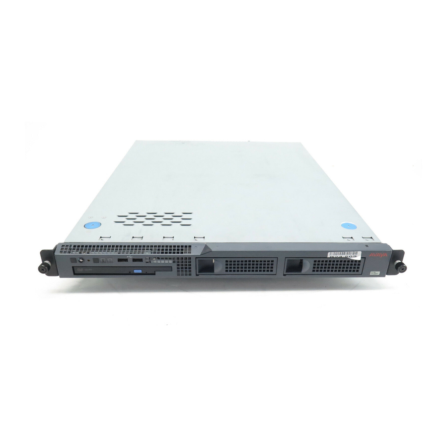
Mounting hardware in the rack Mounting hardware in the rack Getting Started with the Avaya S8500 Media Server with the Avaya G650 Media Gateway information on mounting the hardware in the rack. Avaya S8500 Media Server components Figure 2, Avaya S8500 Media Server, front view,... -
Page 39: Installing The Network Interface Card
Mouse port Installing the network interface card This section describes the steps required to install the optional network interface card (NIC) on the Avaya S8500 Media Server. The control network traffic from the server out to the dedicated customer LAN travels through the NIC. -
Page 40: Backing Up The Media Server
Figure 4: Welcome window Click Continue. Accept the Avaya certificate by clicking Yes. Logon as or dadmin. craft Suppress alarm origination by clicking Yes. Click Launch Maintenance Web Interface. Installing the Avaya S8500 Media Server with an Avaya G650 Media Gateway December 2003... -
Page 41: Powering Down The Media Server
Slide the server cover back from the front panel until the cover’s tabs are released from the top slot of the front panel. Lift the cover straight up and move it away from the server. Installing the Avaya S8500 Media Server with an Avaya G650 Media Gateway December 2003... -
Page 42: Removing The Fan Unit
Position the small faceplate over the Ethernet ports. The faceplate must align with the screw holes on the circuit board. Screw the small faceplate onto the circuit board using the two screws removed in step 1. Installing the Avaya S8500 Media Server with an Avaya G650 Media Gateway December 2003... -
Page 43: Inserting The Network Interface Card
Carefully grasp the new NIC card by the top edge or upper corners and align it with the PCI-2 expansion slot. Press the NIC card firmly into the expansion slot. See Figure 7, Inserting the network interface card, on page 44. Installing the Avaya S8500 Media Server with an Avaya G650 Media Gateway December 2003... -
Page 44: Replacing The Fan Unit
/ 6 WARNING: Be sure that the NIC is completely and correctly seated in the PCI-2 expansion slot of the Avaya S8500 Media Server. Incomplete insertion might cause damage to the system board or the NIC . Position the faceplate so that it fits in the PCI-2 slot using the captive screw to hold it in place. -
Page 45: Powering Up The Media Server
Installing the network interface card Release the retaining tabs on the rails and slide the Avaya S8500 Media Server back into place on the data rack. Locate the marked cable that you removed from the old NIC and plug it into the Ethernet 2 port, which is labeled ACT/LINK A on the small faceplate of the new NIC. -
Page 46: Confirming Original Ethernet Configuration
Select "VLAN 802.1q priority tagging is enabled" if true. Click Change. The status of the configuration update appears in the window. When the update completes, the following message appears: Successfully configured ethernet interfaces Installing the Avaya S8500 Media Server with an Avaya G650 Media Gateway December 2003... -
Page 47: Testing Connectivity To Customer's Network
Verify that the ping was successful. and press Enter, where servername is the host If DNS is administered, type ping servername name of media server. Verify that the ping was successful. Installing the Avaya S8500 Media Server with an Avaya G650 Media Gateway December 2003... -
Page 48: Remote Supervisor Adapter Components
A 10/100 Mbps connector for LAN connectivity. Serial connector Used for serial modem connectivity. ASM RS-485 RJ-14 Not used in the Avaya S8500 Media Server configuration. connector Installing the Avaya S8500 Media Server with an Avaya G650 Media Gateway December 2003... -
Page 49: Connecting The Modems
USB and serial modems cannot connect to rotary lines. A TouchTone line is required. There are two modems on an Avaya S8500 Media Server configuration. One modem connects to the USB port on the front of the Avaya S8500 Media Server. The other modem connects to the RS232 port on the RSA card. - Page 50 Telephone line connecting the serial server. modem to the CO line. Compact flash memory reader USB modem used for Communication connecting to the USB port on the media Manager. server. Installing the Avaya S8500 Media Server with an Avaya G650 Media Gateway December 2003...
-
Page 51: Configuring And Connecting The Hardware
Configuring and connecting the hardware Configuring and connecting the hardware After you have installed the hardware in the rack (see the Getting Started Guide for the Avaya S8500 Media Server for installation information), you must install the Avaya Communication Manager CD, configure the components, and connect them together. -
Page 52: Configuring The Media Server
You must copy all required RSA files listed on the EPW onto your laptop. If you need to install a software update (patch), go to the Avaya Support Web site (http://avaya.com/support) and select Software & Firmware Downloads to identify and copy the required software update. -
Page 53: Powering Up The Media Server
Configuring the media server Copy a blank EPW; go to the Avaya Installation Wizard Web site (http://support.avaya.com/avayaiw). Have the customer fill it out. Use the filled-out EPW provided by the project manager or customer. NOTE: The latest firmware for the programmable circuit packs and media modules may be on the CD. -
Page 54: Installing The Software
To navigate on these screens, use the arrow keys to move to an option, then press the space bar to select the option. Press Enter to submit the screen. Installing the Avaya S8500 Media Server with an Avaya G650 Media Gateway December 2003... - Page 55 Select <OK> and press Enter to partition the hard drive and reformat the partitions Once the drive is properly configured, the program begins the installation process and reports the progress. Installing the Avaya S8500 Media Server with an Avaya G650 Media Gateway December 2003...
-
Page 56: Using The Installation Wizard
When asked "Do you want to suppress alarms?", select "Yes." NOTE: On the initial Web page, some items may not appear at first. These include Launch Avaya Station Administration Wizard in the Administration section and the Upgrade section including Launch Upgrade Tool. - Page 57 - 192.11.13.6 • Gateway IP Address field - 0.0.0.0 • field - 255.255.254.0 Subnet Mask The above information configures the RSA card for the cross-over cable. Installing the Avaya S8500 Media Server with an Avaya G650 Media Gateway December 2003...
-
Page 58: Completing The Remote Supervisor Adapter Configuration
Connect a customer-supplied CAT5 straight-through cable from the media server NIC, port 1 (Eth0) (or the optional dual-port NIC port 1 (Eth2) or port 2 (Eth3), if a dedicated network), to the customer’s network. See Getting Started with the Avaya S8500 Media Server with an Avaya G650 Media Server. -
Page 59: Disconnecting From The Media Server
Verify that the ping was successful. Disconnecting from the media server • Unplug the crossover cable from the services port on the back of the media server. Installing the Avaya S8500 Media Server with an Avaya G650 Media Gateway December 2003... -
Page 60: Configuring The Remote Supervisor Adapter
RSA. The RSA is installed in PCI-X slot 1 of the Avaya S8500 Media Server. Although all the software needed to use the RSA comes installed from the factory, you still need to configure the RSA before you use it. -
Page 61: Before You Get Started
We recommend that for RSA you use an external power source on a different circuit from the Avaya S8500 Media Server. The RSA obtains power from an external power source or from the Avaya S8500 Media Server. For external power, plug the cord from the power-supply adapter into the power connector on the RSA. The power cord must be plugged from the power-supply adapter into the power source. -
Page 62: Connecting And Logging In To The Remote Supervisor Adapter
60 minutes of use before disconnecting. NOTE: If the session times out unexpectedly, click Start New Session and Refresh. Click Continue. Installing the Avaya S8500 Media Server with an Avaya G650 Media Gateway December 2003... -
Page 63: Configuring The Remote Supervisor Adapter
The Advanced System Management Web page is divided into a left navigation pane and a display pane. For security reasons, you must change the default login ID and password when you first log on. Installing the Avaya S8500 Media Server with an Avaya G650 Media Gateway December 2003... -
Page 64: Changing Login Id And Password
Configuring the Remote Supervisor Adapter Changing login ID and password Under ASM Control, click Login Profiles. The system displays the Login Profiles window. Installing the Avaya S8500 Media Server with an Avaya G650 Media Gateway December 2003... - Page 65 Password In the field, type the new password again. Confirm Password Click Save. On the Login Profiles window, scroll down to the bottom and click Save. Installing the Avaya S8500 Media Server with an Avaya G650 Media Gateway December 2003...
-
Page 66: Configuring Advanced System Management
The system displays the System Setting window. In the field, type in the Avaya product ID number from ART. Name The ID number is set to the Avaya default. A new ID number can be entered in the ID number field if needed. In the Contact field, type in the contact information. - Page 67 Select Automatically adjust for daylight savings time changes if daylight savings is used in your area. Click Save. Scroll down to the bottom of the System Settings window and click Save. Installing the Avaya S8500 Media Server with an Avaya G650 Media Gateway December 2003...
-
Page 68: Setting Alarms
Avaya Remote Supervisor Adapter User Guide. Complete the following steps to enter Avaya as an alarm recipient for this location. Under ASM Control, click Alerts. The system displays the Remote Alert Recipients window. Installing the Avaya S8500 Media Server with an Avaya G650 Media Gateway... - Page 69 SNMP alerts. Additional administration must be completed in the Network Protocols section before SNMP over LAN is used. Click Save. This is the only part you must fill out in the Alerts section. Keep the remaining fields as Avaya default settings. NOTE: Testing the alert recipient cannot be done at this time.
-
Page 70: Configuring Network Interfaces
, and fields are set using the Maintenance Web Interface Gateway address Subnet Mask when you configure the Ethernet ports on the Avaya S8500 Media Server. In the field, select Disabled - Use static IP configuration. DHCP If you are not using DHCP, then under the Static IP Configuration heading, verify that the... -
Page 71: Configuring Network Protocols
Hostname field, complete the IP-address-to-hostname mappings by filling out the IP address field. Scroll down and click Save. Under ASM Control, click Restart ASM to reboot. Installing the Avaya S8500 Media Server with an Avaya G650 Media Gateway December 2003... -
Page 72: Backing Up The Configuration
Serial Port > Advanced Modem Settings Ethernet Network Interfaces Advanced Ether Setup Network Interfaces > Advanced Ethernet Setup PPP over Serial Port Network Interfaces SNMP Network Protocols Installing the Avaya S8500 Media Server with an Avaya G650 Media Gateway December 2003... - Page 73 Select • Save this file to disk and then OK if MS Internet Explorer. • Save File, then OK if Netscape Navigator Installing the Avaya S8500 Media Server with an Avaya G650 Media Gateway December 2003...
-
Page 74: Restoring Advanced System Management Configurations
You must restart ASM for the new configuration to take affect. Click OK to confirm that you would like to restart the RSA. Click OK to close your current browser window. Installing the Avaya S8500 Media Server with an Avaya G650 Media Gateway December 2003... -
Page 75: Modifying A File
Under ASM Control, click Serial Port. The system displays the Serial Port window. In the Serial Port section, click Advanced Modem Settings. The system displays the Modem Settings window. Installing the Avaya S8500 Media Server with an Avaya G650 Media Gateway December 2003... -
Page 76: Updating Rsa Or Bios Firmware
Log in to the RSA. In the navigation pane, select Firmware Update under the Tasks heading. The Update Firmware window appears (see Figure 12, Update firmware, on page 77). Installing the Avaya S8500 Media Server with an Avaya G650 Media Gateway December 2003... -
Page 77: Logging Off The Remote Supervisor Adapter
Click OK to close the browser window. Log in to the RSA. Logging off the Remote Supervisor Adapter Select Log Off from the left pane. In the confirmation window, click Yes. Installing the Avaya S8500 Media Server with an Avaya G650 Media Gateway December 2003... -
Page 78: Configuring The Network Interface Card
Select "VLAN 802.1q priority tagging is enabled" if true. Click Change. The status of the configuration update appears in the window. When the update completes, the following message appears: Successfully configured ethernet interfaces Installing the Avaya S8500 Media Server with an Avaya G650 Media Gateway December 2003... -
Page 79: Testing Connectivity To Customer's Network
Verify that the ping was successful. If DNS is administered, type and press Enter, where servername is the host ping servername name of media server. Verify that the ping was successful. Installing the Avaya S8500 Media Server with an Avaya G650 Media Gateway December 2003... -
Page 80: Configuring The Modem
ID and click Logon. Login ID In the Password field, type your password and click Logon. The Integrated Management Standard Management Solutions window appears. Installing the Avaya S8500 Media Server with an Avaya G650 Media Gateway December 2003... - Page 81 On the Review Notices page, click Continue. On the Warning page, click Continue. On the Back Up Data page, click Continue. The Specify how you want to use this wizard page appears. Installing the Avaya S8500 Media Server with an Avaya G650 Media Gateway December 2003...
- Page 82 Click Configure individual services and then click Continue. The Notice page with a menu appears. In the left menu, click Set Modem Interface. The Set Modem Interface window appears. Installing the Avaya S8500 Media Server with an Avaya G650 Media Gateway December 2003...
- Page 83 For example, to change the country code to Japan, type the following command: AT%T19,0,10 Click Change. The system responds with a message indicating a successfully added modem route. Installing the Avaya S8500 Media Server with an Avaya G650 Media Gateway December 2003...
-
Page 84: Configuring The Snmp Modules In The Uninterruptible Power Supplies
The module reports the loss of commercial power and/or the depletion of battery resources. Each UPS’s SNMP module requires a unique IP address, which can be a customer-provided one or the Avaya-provided default one. At a minimum, the following items need to be configured: • IP address •... -
Page 85: Simplex Reliability Configurations
Default Gateway IP address = 198.152.254.202 • Host Table trap receiver IP address = 198.152.254.202 • Local network administrator supplied information as required for Get and Set community name strings. Installing the Avaya S8500 Media Server with an Avaya G650 Media Gateway December 2003... -
Page 86: Setting Selected Traps (Alarming)
UPS on Battery—Indicates AC fail with pending shutdown based on battery reserve available • UPS in Bypass—Failure either Failed UPS or overload • Replace battery—Failure of periodic (28-day) battery test indicating battery needs to be replaced. Installing the Avaya S8500 Media Server with an Avaya G650 Media Gateway December 2003... -
Page 87: Configuring The Snmp Subagent In The Avaya Ethernet Switch (If Used)
Each Avaya Ethernet switch requires a unique IP address, which can be a customer-provided one or the Avaya-provided default one. At a minimum, the following items need to be configured: •... - Page 88 When completed, disconnect the services laptop computer from the Ethernet switch. If two Ethernet switches are present for CNA, repeat steps 1 through 7 for the second switch. Installing the Avaya S8500 Media Server with an Avaya G650 Media Gateway December 2003...
-
Page 89: Customizing The Media Server
Avaya. NOTE: You must use Release 1.11 or a later version of Avaya Site Administration, to be able to administer new features in Release 2.0 of Avaya Communication Manager. Perform these tasks to customize the media server: •... -
Page 90: Resetting Media Server
Control Subnet Address is correct. The subnet address must match the most significant 3 octets (the first 3 groups of digits in the subnet address) of the Server IP address. Installing the Avaya S8500 Media Server with an Avaya G650 Media Gateway December 2003... -
Page 91: Adding Ipsi Information
Subnet Address displayed, it is not the correct one; Avaya Communication Manager does not have the subnet information. After verifying the displayed information, submit this form with or without changes to update Communication Manager with the correct subnet information. - Page 92 IP Control? field to Verify that all the other fields are populated. Press Enter to effect the changes. Repeat steps 1 through 5 for each port network. Installing the Avaya S8500 Media Server with an Avaya G650 Media Gateway December 2003...
-
Page 93: Setting Ipsi Duplication (High/Critical Reliability Only)
Enter to save the translations to the hard drive. save translations Saving translations • Type and press Enter to save the IPSI translations to the hard drive. save translations Installing the Avaya S8500 Media Server with an Avaya G650 Media Gateway December 2003... -
Page 94: Installing The Media Gateways
Installing patch panels on page 167 The Avaya S8500 Media Server works with either a G650, MCC1, SCC1, G600, or CMC1 Media Gateway. In addition a G700 Media Gateway may be used if one of the other media gateways with a TN799DP Control-LAN (C-LAN) circuit pack is installed. - Page 95 Connecting the media gateway to the main distribution frame on page 185 • Connecting the main distribution frame to stations and the public switched telephone network page 191 Installing the Avaya S8500 Media Server with an Avaya G650 Media Gateway December 2003...
-
Page 96: Checking And Inspecting The Order
The optional G650 Media Gateways for port hardware only are shipped with AC or DC power cord or international power cord kit, mounting screw kits, TDM/LAN bus cable, and EMI Gaskets. Installing the Avaya S8500 Media Server with an Avaya G650 Media Gateway December 2003... -
Page 97: Checking Circuit Packs
Be sure all circuit packs are fully inserted into the proper slots according to the system diagram provided by the project manager. Report any discrepancies in circuit pack type or quantity to your Avaya representative. For detailed circuit pack descriptions, see the Hardware Guide for the Avaya Communication... -
Page 98: Unpacking And Inspecting The Media Gateways-Mcc1
Red-tag all defective and over-shipped equipment and return according to the nearest Material Stocking Location (MSL) instructions. To contact the Avaya Order Management group in the United States, call 1-800-772-5409. For international customers, contact your order service agent. Direct all short-shipped reports to the nearest MSL. Contact the appropriate location for specific instructions. -
Page 99: Connecting Ac Power And Ground
Verify that the customer’s branch circuit and/or power distribution strip are adequate with respect to overload and overcurrent protection. Approved grounds See the job aid entitled Approved Grounds. Installing the Avaya S8500 Media Server with an Avaya G650 Media Gateway December 2003... -
Page 100: Installing The G650 Media Gateway
DC feed power cable (Cable from the customer’s DC plant to the cabinet backplane. Defaults to 30 feet in length) 405362641 AC power cord—Domestic (USA, Canada, Mexico, Japan, and much of the Caribbean) Installing the Avaya S8500 Media Server with an Avaya G650 Media Gateway December 2003... - Page 101 700276389 TN2312 IPSI adapter cable 700284623 Dual network interface card (NIC) ‡ 104042163 1/4 inch (.6 centimeters) apparatus blank (158G) /////////////// ////////////////////////////////////////////////////////////// /////////////// ////////////// /////// Installing the Avaya S8500 Media Server with an Avaya G650 Media Gateway December 2003...
- Page 102 104386545 4C1S analog line protector - solid state with heat coil 105581086 4C3S-75dDigital voice circuit protector - solid state 406144907 ITW LINX gas tube, avalanche suppress Installing the Avaya S8500 Media Server with an Avaya G650 Media Gateway December 2003...
-
Page 103: Checking Circuit Packs
Document (CSD). See Table 7, G650 Media Gateway circuit pack placement, on page 103. Report any discrepancies in circuit pack type or quantity to your Avaya representative. Table 7: G650 Media Gateway circuit pack placement Circuit pack information Placement information... - Page 104 ACTIVE RING msdlrck4 KLC 090903 Figure notes Media server — 1 Carrier B Carrier C Ethernet switch (if used) UPS 1 Carrier D Carrier A Carrier E Installing the Avaya S8500 Media Server with an Avaya G650 Media Gateway December 2003...
-
Page 105: Checking The Ventilation And The G650 Media Gateway Rack
If the rack is not secured to the floor, do not proceed with the installation. Avaya does not recommended that you use enclosed data cabinets, because they might not allow sufficient ventilation to the G650 Media Gateway. -
Page 106: Setting The Carrier Address Id
Figure 17, Setting the G650 Media Gateway carrier address ID, on page 107. Place the address paddleboard in the connector slot that you want, A, B, C, D, or E. Installing the Avaya S8500 Media Server with an Avaya G650 Media Gateway December 2003... - Page 107 Figure 16: Removing the fan assembly fndprem2 LAO 071503 Figure 17: Setting the G650 Media Gateway carrier address ID -48 VDC -48 VDC RETURN swdlpdle LAO 072403 Installing the Avaya S8500 Media Server with an Avaya G650 Media Gateway December 2003...
-
Page 108: Mounting One G650 Media Gateway
G650 Media Gateway match all the mounting bracket slots on the mounting template. See Figure 18, Rack hole spacing and first mounting screws placement, on page 109. Installing the Avaya S8500 Media Server with an Avaya G650 Media Gateway December 2003... - Page 109 Insert two mounting screws into the left and right rails of the rack in the holes noted in step 4. Leave enough space between the screw head and the rail surface for the mounting bracket. See Figure 19, Mounting the medial gateway, on page 110. Installing the Avaya S8500 Media Server with an Avaya G650 Media Gateway December 2003...
- Page 110 Follow the same steps to install the G650 Media Gateway with mounting bracket in the medial position. See Figure 19, Mounting the medial gateway, on page 110. Installing the Avaya S8500 Media Server with an Avaya G650 Media Gateway December 2003...
- Page 111 Installing the TN2312BP IPSI adapter on page 112. If you are installing multiple G650 Media Gateways, proceed to Mounting two to five G650 Media Gateways on page 112. Installing the Avaya S8500 Media Server with an Avaya G650 Media Gateway December 2003...
-
Page 112: Mounting Two To Five G650 Media Gateways
If you want to use the external alarm function, attach an 9-pin external alarm cable to the TN2312BP IPSI adapter. For the unterminated end, see the Job Aid entitled Connector and Cable Diagrams (Pinout Charts). Installing the Avaya S8500 Media Server with an Avaya G650 Media Gateway December 2003... -
Page 113: Approved Ground
114 for a single G650 Media Gateway, or Figure 23, Grounding for multiple G650 Media Gateways, on page 114 for 2 or more G650 Media Gateways. Installing the Avaya S8500 Media Server with an Avaya G650 Media Gateway December 2003... - Page 114 -48 VDC -48 VDC RETURN -48 VDC -48 VDC RETURN cadpgrn2 LAO 072403 Figure notes 10 AWG (#25) (6 mm ) wire to coupled bonding conductor (CBC) Installing the Avaya S8500 Media Server with an Avaya G650 Media Gateway December 2003...
-
Page 115: Ac Power
If the AC outlet tests indicate that the power requirements are not met, your customer must contact a licensed electrician. DO NOT install the system until all requirements are met. Installing the Avaya S8500 Media Server with an Avaya G650 Media Gateway December 2003... - Page 116 If the voltage readings do not measure the values given, the AC outlet is improperly wired. DO NOT INSTALL THE SYSTEM. Advise the customer to have a licensed electrician correct the problem. You are now ready to power the system. Installing the Avaya S8500 Media Server with an Avaya G650 Media Gateway December 2003...
-
Page 117: Dc Power
Connect the DC feed cable for each G650 Media Gateway to the DC power source. Connect the red insulated 10 AWG lead to the -48V Return (positive) source. Connect the black insulated 10AWG lead to the -48 VDC (negative) source. Installing the Avaya S8500 Media Server with an Avaya G650 Media Gateway December 2003... -
Page 118: Uninterruptible Power Supply
CAUTION: The major alarm contacts are designed to be connected ONLY to an UPS that can indicate that it is on backup power. For most non-Avaya UPSs, you should not use the major external device leads. Installing the Avaya S8500 Media Server with an Avaya G650 Media Gateway... -
Page 119: G650 Media Gateway Power Switch
UPS.) NOTE: If an Avaya UPS is wired as recommended, holdover time for each power outage is 1 minute before an automatic shutdown. An UPS can handle any subsequent power outage based on its total battery capacity. - Page 120 Figure 25: Power supply for the G650 Media Gateway FAN OR POWER FAIL FAN AND POWER OK AC INPUT DC INPUT ACTIVE RING Figure notes Power supply Installing the Avaya S8500 Media Server with an Avaya G650 Media Gateway December 2003...
-
Page 121: Cabling The G650 Media Gateways
Install the upper terminator of the TDM/LAN bus cable on the right end of the TDM/LAN bus in media gateway B. Flip over the routing slot plates and reinstall both. Once the plates are reinstalled, the ends of the routing slots are covered. Installing the Avaya S8500 Media Server with an Avaya G650 Media Gateway December 2003... -
Page 122: Cabling The Third Media Gateway
Otherwise continue to Cabling the fifth media gateway on page 123. Installing the Avaya S8500 Media Server with an Avaya G650 Media Gateway December 2003... -
Page 123: Cabling The Fifth Media Gateway
Reinstall the fan assemblies and tighten the 7 screws on each media gateway. (All knurled screws must be tightened securely so that they cannot be loosened without the use of a tool.) Installing the Avaya S8500 Media Server with an Avaya G650 Media Gateway December 2003... -
Page 124: Installing Circuit Packs In The G650 Media Gateway
IPSI adapter. Figure 26, G650 Media Gateway IPSI adapter, on page 125 shows the IPSI adapter. Installing the Avaya S8500 Media Server with an Avaya G650 Media Gateway December 2003... - Page 125 Figure 26: G650 Media Gateway IPSI adapter addpipsi LAO 081303 Installing the Avaya S8500 Media Server with an Avaya G650 Media Gateway December 2003...
-
Page 126: Installing An Mcc1 Media Gateway
This section describes how to install MCC1 Media Gateways. Figure 27, Typical MCC1 Media Gateway, on page 127 shows a typical MCC1 Media Gateway. Installing the Avaya S8500 Media Server with an Avaya G650 Media Gateway December 2003... - Page 127 How much AC power? on page 131 or Connecting DC power and ground on page 150 • Connecting remote power off cable, if required on page 135 Installing the Avaya S8500 Media Server with an Avaya G650 Media Gateway December 2003...
-
Page 128: Positioning And Bolting Down For Earthquakes
Roll the media gateway out of the way and drill four 1/2-inch (1.27-centimeter) diameter holes about 1.5 inch (3.8 centimeter) deep at the locations marked in Step 2. Insert concrete floor anchors (STARR part number 3425) into the holes. Installing the Avaya S8500 Media Server with an Avaya G650 Media Gateway December 2003... - Page 129 10 inches (25 centimeters), cut the threaded rod 11 inches (27.9 centimeters) long. When all four threaded rods are cut, replace the raised floor panels removed in Step 5. Installing the Avaya S8500 Media Server with an Avaya G650 Media Gateway December 2003...
- Page 130 4 inches (10.16 cm) Leveling foot 3/8 - 16 threaded rod raised variable floor height 3/8 - 16 Concrete floor anchor concrete subfloor cab_base CJL 052096 Installing the Avaya S8500 Media Server with an Avaya G650 Media Gateway December 2003...
-
Page 131: How Much Ac Power
Non-US 5-wire, Y, 220/380 VAC. This source has 3 hot wires, 1 neutral wire, and 1 ground wire. • Non-US Delta, 4-wire, 220 or 240 VAC. This source has 3 hot wires and 1 ground wire. Installing the Avaya S8500 Media Server with an Avaya G650 Media Gateway December 2003... - Page 132 Bonding Conductor (CBC) ground block at the main distribution frame (MDF). The coupled bonding conductor (CBC) wires are installed and terminated in Installing the coupled bonding conductor on page 208. Installing the Avaya S8500 Media Server with an Avaya G650 Media Gateway December 2003...
-
Page 133: Installing The Avaya S8500 Media Server With An Avaya G650 Media Gateway December
AC Load Center Media Gateway Ground Terminal Less than 50 Wire feet (15.2 m) Block Approved Ground 6 AWG (#40) (16 mm ) Media Gateway GROUND Wire Installing the Avaya S8500 Media Server with an Avaya G650 Media Gateway December 2003... - Page 134 Connect a 6 AWG (#40) (16 mm ) ground wire to an unused terminal on the single-point ground block. Route the ground wire to the AC load center ground and connect. Installing the Avaya S8500 Media Server with an Avaya G650 Media Gateway December 2003...
- Page 135 Route the opposite end of the wires to the EPO switch. The opposite end of the RPO cable connects to the internal relay. NOTE: The EPO switch and the auxiliary contacts (inside the EPO switch assembly) are customer-provided. Installing the Avaya S8500 Media Server with an Avaya G650 Media Gateway December 2003...
- Page 136 Figure 32: Remote power off cable connections — Part 1 psdf001a LAO 091103 Figure notes External Alarm Cable Connector Pin 6 (-RPO) RPO Connector Pin 2 (+RPO) Circuit Breakers External Alarm Cable Installing the Avaya S8500 Media Server with an Avaya G650 Media Gateway December 2003...
- Page 137 Plug the external alarm cable into the connector shown in Figure 34, External alarm cable connection, on page 138. NOTE: Route the opposite end of the cable to the MDF. Installing the Avaya S8500 Media Server with an Avaya G650 Media Gateway December 2003...
- Page 138 J58890CH Power Distribution unit in the cabinet. These alarms are provided by isolated contact closures rated at 60 VDC max, 5mA max. Installing the Avaya S8500 Media Server with an Avaya G650 Media Gateway December 2003...
- Page 139 GMCC BNA, BTW, and BIU RFA2 01C0902 minor RECT GMCC Rectifiers 1The System Parameters Customer-Options screen must have the External Device Alarm Admin field set to yes. Installing the Avaya S8500 Media Server with an Avaya G650 Media Gateway December 2003...
-
Page 140: Wiring Block Diagram
01C0902 minor RECT Unplug rectifiers one at a time until this alarm comes in indicating you no longer have N+1 sparing of rectifiers for your load. Installing the Avaya S8500 Media Server with an Avaya G650 Media Gateway December 2003... - Page 141 Be sure the main power to the power distribution unit is OFF. At the power distribution unit, set all carrier circuit breakers OFF. Figure 36: Typical small battery assembly Battery connector psdfbatb RPY 061797 Installing the Avaya S8500 Media Server with an Avaya G650 Media Gateway December 2003...
- Page 142 Bonding Conductor (CBC) ground block at the main distribution frame (MDF). The coupled bonding conductor (CBC) wires are installed and terminated in Installing the coupled bonding conductor on page 208. Installing the Avaya S8500 Media Server with an Avaya G650 Media Gateway December 2003...
- Page 143 NOTE: If a media gateway is located remotely (in a separate room or building), route the media gateway GROUND wire to an approved protective ground. Installing the Avaya S8500 Media Server with an Avaya G650 Media Gateway December 2003...
- Page 144 Block AC Load Center Single-Point Ground 6 AWG (#40) (16 mm ) Media Approved Ground Gateway GROUND Wire Over 50 ft. (15.2 m) Single-Point Ground Block Installing the Avaya S8500 Media Server with an Avaya G650 Media Gateway December 2003...
- Page 145 Connect the RPO wires to the auxiliary contacts on the EPO switch. See Figure 41, External alarm cable connection, on page 147. NOTE: The EPO switch and the auxiliary contacts for the RPO connection are customer-supplied. Installing the Avaya S8500 Media Server with an Avaya G650 Media Gateway December 2003...
- Page 146 Figure 40: Remote power off cable connections — Part 2 Power Distribution Unit To Carriers A to E Shunt Relay Battery (K1) Cabinet Ground Terminal RPO Cable Auxiliary Contacts in EPO Switch 0026_3 RBP 080196 Installing the Avaya S8500 Media Server with an Avaya G650 Media Gateway December 2003...
- Page 147 The Alt Name given to the alarm should be “AC”. field should be Description GMCC AC input power 2The System Parameters Customer-Options screen must have External Device Alarm Admin field set to yes. Installing the Avaya S8500 Media Server with an Avaya G650 Media Gateway December 2003...
- Page 148 +48 V battery lead is called -48 VDC RETURN and it will be connected to the cabinet frame ground. Connect the temperature sensor cable, from the battery cabinet, to J20. Installing the Avaya S8500 Media Server with an Avaya G650 Media Gateway December 2003...
- Page 149 Verify the meter reads 0 VAC. If not, have a qualified electrician correct the problem. Set all media gateway power modules . Plug the AC power cable into the receptacle. Installing the Avaya S8500 Media Server with an Avaya G650 Media Gateway December 2003...
-
Page 150: Dc Power Distribution Unit J58890Cf
153 • Connecting DC battery cabinet to DC power cabinet on page 153 • If necessary, Connecting mixed AC/DC power and ground on page 158 Installing the Avaya S8500 Media Server with an Avaya G650 Media Gateway December 2003... - Page 151 DC battery cabinet and the ground discharge bar in the DC power cabinet. See Figure 44, Typical power and ground for a DC power cabinet, on page 151. Installing the Avaya S8500 Media Server with an Avaya G650 Media Gateway December 2003...
- Page 152 Connect a 6 AWG (#40) wire to the DC battery cabinet and DC power cabinet. Route the wires to the AC mains single-point ground block and connect. Installing the Avaya S8500 Media Server with an Avaya G650 Media Gateway December 2003...
-
Page 153: Ac Power Distribution Unit J58890Ce
The type of power required is shown on the media gateway’s rear door. The connect AC power and ground procedures apply to the AC-powered MCC1 Media Gateways. Installing the Avaya S8500 Media Server with an Avaya G650 Media Gateway December 2003... - Page 154 If the media gateway is located remotely (in a separate room or building), connect the media gateway GROUND wire to an approved ground. Repeat connecting each media gateway to the single-point ground block. Installing the Avaya S8500 Media Server with an Avaya G650 Media Gateway December 2003...
- Page 155 GROUND wire to the media gateway ground block. See Figure 29, Typical media gateway ground location, on page 133. Route the opposite end of the wire to the single-point ground block and connect. Installing the Avaya S8500 Media Server with an Avaya G650 Media Gateway December 2003...
- Page 156 Block AC Load Center Single-Point Ground 6 AWG (#40) (16 mm ) Media Approved Ground Gateway GROUND Wire Over 50 ft. (15.2 m) Single-Point Ground Block Installing the Avaya S8500 Media Server with an Avaya G650 Media Gateway December 2003...
- Page 157 Set the DVM to the 250 volt range. Carefully measure the voltage between the hot and neutral side of the receptacle. The neutral wire is white, the hot wire is black. Installing the Avaya S8500 Media Server with an Avaya G650 Media Gateway December 2003...
-
Page 158: Connecting Mixed Ac/Dc Power And Ground
1 AWG up to 50 feet (15.2m) or engineered for AC power cord less than 0.5 volt drop per conductor AC power source To Coupled Bonding Conductor terminal block at Main Distribution Frame Installing the Avaya S8500 Media Server with an Avaya G650 Media Gateway December 2003... -
Page 159: Cabling The Mcc1 Media Gateways-Center Stage Switch
If the media gateway in the TO column in the running list is located remotely from the FROM media gateway, connect to the TO media gateway by way of the LIU. Installing the Avaya S8500 Media Server with an Avaya G650 Media Gateway December 2003... -
Page 160: Connecting Duplex- Or High-Reliability Center Stage Switch-Connected Pn1 With One Switch Node
SNI slots to 3 and 20 (the left most and right most of the unused slots). Next, use 4 and 19, and so forth. Add links to the PNs in alternating order (20, 3, 19, 4, 18, 5, and so forth). Installing the Avaya S8500 Media Server with an Avaya G650 Media Gateway December 2003... -
Page 161: Connecting Critical Reliability Css-Connected Pn1 With One Switch Node
Connect the two groups of 1 to 15 cables between PN1 and each of the other PNs in an alternating port slot order: 20, 3; 19, 4; 18, 5; and so forth. Installing the Avaya S8500 Media Server with an Avaya G650 Media Gateway December 2003... - Page 162 KLC 031202 Figure notes Media Gateway 1 (PN1 with 1 Duplex Switch H600-278 Metallic Cable Node) To other Port Networks Port Network 2 through 16 Installing the Avaya S8500 Media Server with an Avaya G650 Media Gateway December 2003...
-
Page 163: Installing The G350 Media Gateway
Local Spare Processor (LSP) may be added to either an Avaya S8700 Multi-Connect or IP Connect configuration or Avaya S8500 Media Server. To add a G350 Media Gateway, you must have a TN799DP Control-LAN (C-LAN) circuit pack installed in the G650 Media Gateway. The G350 Media Gateway is an endpoint on the C-LAN circuit pack. - Page 164 G650 Media Gateway Analog connectivity: analog telephones, lines, and trunks IP telephones off the customer’s network Ethernet switch (optional) Voice mail: connected via IP Installing the Avaya S8500 Media Server with an Avaya G650 Media Gateway December 2003...
-
Page 165: Installing The G700 Media Gateway
Installing the G700 Media Gateway A G700 Media Gateway or a G700 Media Gateway with an Avaya S8300 Media Server configured as a Local Spare Processor (LSP) may be added to either a Avaya S8700 Multi-Connect or IP Connect configuration or Avaya S8500 Media Server. To add a G700 Media Gateway, you must have a TN799DP Control-LAN (C-LAN) circuit pack installed in the MCC1, SCC1, CMC1, G650, or G600 Media Gateway. - Page 166 G650 Media Gateway Analog connectivity: analog telephones, lines, and trunks IP telephones off the customer’s network Ethernet switch (optional) Voice mail: connected via IP Installing the Avaya S8500 Media Server with an Avaya G650 Media Gateway December 2003...
-
Page 167: Installing Patch Panels
Cross-connect the port circuit packs to the G650 Media Gateway patch panels (or other standard 110A cross-connect equipment). See Figure 54, Example cross-connect field patch panel connections, on page 169. Installing the Avaya S8500 Media Server with an Avaya G650 Media Gateway December 2003... - Page 168 Figure notes Circuit pack amphenol connectors 24 port patch panels and B25A cables 8 port patch panel IP Server Interface adapter and To network green CAT5 cable Installing the Avaya S8500 Media Server with an Avaya G650 Media Gateway December 2003...
- Page 169 Port MET Line Port Tie Trunk 4 Port Tie Trunk w/ E&M Signaling Port Analog Port CO Port Data Line Port DID Port Digital Port Hybrid Port BRI Port Analog Port Digital Port Analog Port Digital widfccf2 EWS 102798...
-
Page 170: Installing The Main Distribution Frame
(PSTN). The tasks include the following: • Space requirements and layout on page 171 • Installing main distribution frame hardware on page 174 Installing the Avaya S8500 Media Server with an Avaya G650 Media Gateway December 2003... -
Page 171: Space Requirements And Layout
Sizing 25-pair and multiple 25-pair station cables on page 172 • 3-pair station cable circuits on page 172 • 4-pair station cable circuits on page 173 Installing the Avaya S8500 Media Server with an Avaya G650 Media Gateway December 2003... - Page 172 This will provide additional pairs for growth and compensate for every twenty-fifth pair in a cable that is not used. Installing the Avaya S8500 Media Server with an Avaya G650 Media Gateway December 2003...
- Page 173 NOTE: This formula may not compensate for the unused 25th pair in all cases. If not, it must be allowed for. Installing the Avaya S8500 Media Server with an Avaya G650 Media Gateway December 2003...
-
Page 174: Installing Main Distribution Frame Hardware
175 shows a detailed example of the G600 Media Gateway cables connecting media gateways and satellite closets to the MDF. This figure shows the cross-connections for one example station circuit. Installing the Avaya S8500 Media Server with an Avaya G650 Media Gateway December 2003... - Page 175 103A or Modular Wall Jack Purple Field 4-Pair Line Cord Yellow Field To Line Circuit Pack Green Field To Trunk Circuit Pack Satellite Closet To Network Interface Installing the Avaya S8500 Media Server with an Avaya G650 Media Gateway December 2003...
-
Page 176: Main Distribution Frame Cross-Connect Fields
The preferred location of the MDF is directly behind the media gateways. Figure 57, Typical 110A-type terminal blocks (G650 Media Gateway), on page 177 shows a typical installation using 110A-type terminal blocks. Installing the Avaya S8500 Media Server with an Avaya G650 Media Gateway December 2003... - Page 177 Figure notes G600 Media Gateways in rack Station Distribution Field Z113A Cable Slack Manager Port Distribution Field 25-Pair Cable to Media Gateway Trunk/Auxiliary Field Station Cables Installing the Avaya S8500 Media Server with an Avaya G650 Media Gateway December 2003...
-
Page 178: Main Distribution Frame Labels
Figure notes Floor or Building Identification (write as Information Outlet required Site/Satellite Closet Media Gateway Tie Circuit Carrier (leave blank for G600 Media Floor Gateway) Building Slot Installing the Avaya S8500 Media Server with an Avaya G650 Media Gateway December 2003... -
Page 179: Mounting 110A- Or 110P-Type Terminal Blocks On The Wall
If installing a vertical patch cord trough in the distribution field, repeat Step 6. Repeat Steps 11 and 12 until all the terminal blocks and vertical patch cord troughs in the distribution field are installed. Installing the Avaya S8500 Media Server with an Avaya G650 Media Gateway December 2003... - Page 180 47.5 inches (120.6 centimeters) 6.6 feet (2 meters) Horizontal Line 7.68 inches (19.5 centimeters) AC Power Strip 7/8-inch (2.22 centimeters) Floor Line 5.31 inches (13.5 centimeters) Installing the Avaya S8500 Media Server with an Avaya G650 Media Gateway December 2003...
-
Page 181: Mounting 110P-Type Terminal Blocks On A Frame
A cable support structure, apparatus mounting 1110C1, mounts directly on top of the 1110A2 and provides support for all cables routed to and from the frame. See Table 13, Apparatus mounting frame ordering information, on page 182 Installing the Avaya S8500 Media Server with an Avaya G650 Media Gateway December 2003... - Page 182 Comcode 1110A2 Apparatus Mounting Frame 104032495 1110C1 Cable Support Assembly 104175120 1110A1 End Dress Panel 104176268 2110A1 Top Dress Panel 104176276 2110B1 Bottom Dress Panel 104176284 Installing the Avaya S8500 Media Server with an Avaya G650 Media Gateway December 2003...
-
Page 183: Installing Cable Slack Managers
Figure 62: Cable routing through Cable Slack Manager—example for MCC1 Media Gateway cbdfflr CJL 102396 Figure notes Top of Media Gateway Spare Center Troughs Cable Slack Manager Media Gateway Trough for Port Cables Cable Clamp Installing the Avaya S8500 Media Server with an Avaya G650 Media Gateway December 2003... - Page 184 Cable Slack Manager (Cover Removed) Cable Clamps Main Distribution Frame (MDF) Cable Ties (Optional) Route Cables Along Path Shown Power Cord Port Cables Cable Slack Manager Installing the Avaya S8500 Media Server with an Avaya G650 Media Gateway December 2003...
-
Page 185: Connecting The Media Gateway To The Main Distribution Frame
Figure 64: Equipment room cabling labels 1 A 2 labels LJK 060396 Figure notes Purple Label (Port Cable) Yellow Label (Auxiliary) Blue/Yellow Label (Building and Blue/Yellow Label (Site or Floor) Satellite) Installing the Avaya S8500 Media Server with an Avaya G650 Media Gateway December 2003... - Page 186 It can also be installed on the skin of the cable near the connector. Figure 65: Self-stick label on 25-pair cable connector Installing the Avaya S8500 Media Server with an Avaya G650 Media Gateway December 2003...
-
Page 187: Cable Routing Guidelines
Media Gateway(s) Cable Slack Manager Number 1 To Building Cables Trunk/Auxiliary Field 10 AWG (#25) (6 square millimeters) Station Distribution Field Wire to Coupled Bonding Conductor Installing the Avaya S8500 Media Server with an Avaya G650 Media Gateway December 2003... - Page 188 Coil the cable around the columns in the cable slack manager to store cable slack. The first run should always go across the full length of the 5 columns in the cable slack manager. Installing the Avaya S8500 Media Server with an Avaya G650 Media Gateway December 2003...
-
Page 189: Trunk Cables Among Network Interface, Sneak Fuse Panel, And Media Gateway
Install a self-sticking port label on the rear of each connector on the B25A connector cable. See Figure 68, Self-stick label on 25-pair cable connector, on page 190. Labels should be positioned so the cabinet connector retainers do not obscure them. Installing the Avaya S8500 Media Server with an Avaya G650 Media Gateway December 2003... - Page 190 Store the excess cable in the cable slack manager. Repeat Steps 2 through 6 until all cables are installed. Figure 68: Self-stick label on 25-pair cable connector Installing the Avaya S8500 Media Server with an Avaya G650 Media Gateway December 2003...
-
Page 191: Connecting The Main Distribution Frame To Stations And The Public Switched Telephone Network
Use a male-to-male cable to connect between the equipment room and satellite location. Staggered finger cables are recommended for all multiple 25-pair station cables and are available in both double-ended and single-ended types. Installing the Avaya S8500 Media Server with an Avaya G650 Media Gateway December 2003... - Page 192 Use this cable when 4-pair station cables are to be field-terminated on the 110- type terminal blocks in the equipment room or satellite closet and the information outlets require push-on connections Installing the Avaya S8500 Media Server with an Avaya G650 Media Gateway December 2003...
-
Page 193: Closets
• — 110PE1-300CT/FT 25-pair connector on the white field and field-terminated on the blue field • — 110PE1-300FT Field-terminated on both the white and blue fields Installing the Avaya S8500 Media Server with an Avaya G650 Media Gateway December 2003... -
Page 194: Site Locations
195 • Connected cable station adapters on page 200 Lists of telephones and consoles currently sold are provided in Connectable telephones and consoles page 233. Installing the Avaya S8500 Media Server with an Avaya G650 Media Gateway December 2003... -
Page 195: 4-Pair Station Circuits
Four-pair station cables can be run directly from a satellite location to the information outlets as previously described. NOTE: Bridged taps are not allowed on any part of the station wiring. Installing the Avaya S8500 Media Server with an Avaya G650 Media Gateway December 2003... - Page 196 Figure 71: 4-pair run to equipment room or satellite location r764798a CJL 030796 Figure notes Station Side of MDF or Satellite Location DIW Station Cable (D-Inside Wire) 4-Pair Circuit Information Outlet Blue Field Installing the Avaya S8500 Media Server with an Avaya G650 Media Gateway December 2003...
- Page 197 4-Pair Connecting Blocks 258A or BR2580A Adapter Purple Field Information Outlet Patch Cord or Cross-Connect Jumpers 4-Pair Circuit (DIW station cable (D- Inside Wire)) Blue Field Installing the Avaya S8500 Media Server with an Avaya G650 Media Gateway December 2003...
- Page 198 To Media Gateway (3-Pair Modularity) 4-Pair Circuit (DIW Station Cable [D- A25D Cable (3-Pair Circuits) Inside Wire]) B25A Cable Part of Satellite Location 4-Pair Circuits (B25A Cable) Installing the Avaya S8500 Media Server with an Avaya G650 Media Gateway December 2003...
- Page 199 356A Adapter Blue Field Information Outlet Patch Cord or Cross-Connect Jumpers 3-Pair Circuit in 4-Pair Wire To Media Gateway (3-Pair Modularity) DIW Station Cable (D-Inside Wire) Installing the Avaya S8500 Media Server with an Avaya G650 Media Gateway December 2003...
-
Page 200: Connected Cable Station Adapters
201. Figure 75: 258A and BR2580A Adapters crdfadp CJL 101596 Figure notes BR2580A Adapter 25-Pair Male Ribbon Connector 258A Adapter 4-Pair Modular Jacks (8 Pins) Installing the Avaya S8500 Media Server with an Avaya G650 Media Gateway December 2003... - Page 201 102605136 BR2580A Adapter 403384720 356A Adapter 104158829 400B Adapter 103848859 400B2 Adapter 104152558 ZD8AJ Adapter 103881421 451 Adapter - Gray 103942272 451 Adapt. - White 103786240 Installing the Avaya S8500 Media Server with an Avaya G650 Media Gateway December 2003...
-
Page 202: Completing A Provisioning Plan
• Route from equipment room through site/satellite closets to each endpoint • Auxiliary power supply, if required (main distribution frame (MDF), site/satellite closet, or information outlet) Installing the Avaya S8500 Media Server with an Avaya G650 Media Gateway December 2003... - Page 203 PORT ASSIGNMENT RECORD CARRIER Page Extension Voice Voice Bldg Number Terminal Terminal Adjunct Slot Port Jack* Old Type Color Module Power* User Name/Use Slot CKT PK Type * To be completed by installation technician r764787 PDH 071596...
-
Page 204: Installing Sneak Current And Off Premise Protection
Figure 78, Model 507B sneak fuse panel, on page 205. See Table 17, Sneak fuse panel ordering information, on page 205 for ordering information. Installing the Avaya S8500 Media Server with an Avaya G650 Media Gateway December 2003... - Page 205 157B connecting block. Fifty protectors are required per block. Install the 507B near the network interface or patch panels with locally obtained #12 x 3/4-inch screws (or equivalent). Installing the Avaya S8500 Media Server with an Avaya G650 Media Gateway December 2003...
- Page 206 26/1 27/2 28/3 29/4 30/5 31/6 32/7 33/8 34/9 35/10 36/11 37/12 38/13 39/14 40/15 41/16 42/17 43/18 44/19 45/20 46/21 47/22 48/23 49/34 50/25 Installing the Avaya S8500 Media Server with an Avaya G650 Media Gateway December 2003...
-
Page 207: Installing Sneak Fuse Panels
Repeat the procedure for each sneak fuse panel. Secure the B25A cable to the panel with the captive screw on the connector and a supplied cable tie. Installing the Avaya S8500 Media Server with an Avaya G650 Media Gateway December 2003... -
Page 208: Installing The Coupled Bonding Conductor
Route the 10 AWG (#25) (6 square millimeters) ground wire to the CBC ground terminal bar at the MDF. Tie wrap the ground wire to the inside wiring cable. Installing the Avaya S8500 Media Server with an Avaya G650 Media Gateway December 2003... - Page 209 DC Battery Cabinet Ground Discharge Bar Main AC Supply (AC Mains) DC Power Cabinet Single-point Ground Block System Single-point Ground Connector Ground Wire To Next DC-powered Media Gateway Installing the Avaya S8500 Media Server with an Avaya G650 Media Gateway December 2003...
-
Page 210: Installing And Administering The Patch Cord/Jumper
212 shows an example labeling scheme for 4-pair circuits from the equipment room to the information outlets. The labeling scheme for 3-pair circuits from the MDF to a satellite location. Installing the Avaya S8500 Media Server with an Avaya G650 Media Gateway December 2003... - Page 211 Purple Row on 110 Terminal Block To Port Connector on Media Gateway Blue Row on 110 Terminal Block (Media Gateway 1, Position B, Slot 03) Central Location for Terminals 1 through Installing the Avaya S8500 Media Server with an Avaya G650 Media Gateway December 2003...
-
Page 212: Labeling Expansion Control Carrier Cable
Place the appropriate AUX connector label on the assigned 110-type terminal block row. On the expansion control carrier cable, place a yellow auxiliary label on the connectors at each end of the cable. Write “AUX” on each label. Installing the Avaya S8500 Media Server with an Avaya G650 Media Gateway December 2003... -
Page 213: Connecting Expansion Control Carrier Outputs Cable (Mcc1 Media Gateway Only)
Label connectors on each end of the cables that connect to the media gateway. Route the cables down the sides of the media gateway and store the excess cable slack in the cable slack manager as previously described. Installing the Avaya S8500 Media Server with an Avaya G650 Media Gateway December 2003... - Page 214 Connector (MCC1 Media Gateway only) Sneak Fuse Panel Concentrator Cable (WP90929, List 1) B25A Cable Concentrator Cable (WP90929, List 3) Central Office Trunks A25D (Male-to-Male) Cable Media Gateway Installing the Avaya S8500 Media Server with an Avaya G650 Media Gateway December 2003...
-
Page 215: Connecting Trunk Pairs To Media Gateway Using Jumper Wires To Establish 3-Pair Modularity
1 4 7 10 13 16 19 22 1 4 7 10 13 16 19 22 r758425b MMR 031496 Figure notes Green Field Pairs 1-Pair Jumpers Purple Field Installing the Avaya S8500 Media Server with an Avaya G650 Media Gateway December 2003... - Page 216 1 2 3 4 5 6 7 8 9 10 11 12 1 2 3 4 5 6 7 8 9 10 11 12 r758537b MMR 031496 Figure notes Green Field Pairs 1-Pair Jumpers Purple Field Installing the Avaya S8500 Media Server with an Avaya G650 Media Gateway December 2003...
-
Page 217: Avaya Rsa Defaults
Executing the Restore Defaults option in the navigation pane removes the Avaya defaults. Avaya defaults can be restored manually using the information found in this document or by restoring the Avaya default file. The Avaya default file can be found at http://support.avaya.com... - Page 218 Warning Alerts Single fan failure Enabled Temperature Enabled Voltage Enabled Redundant power supply Disabled System Alerts Boot failure Enabled Loader timeout Enabled O/S timeout Enabled Enabled Installing the Avaya S8500 Media Server with an Avaya G650 Media Gateway December 2003...
- Page 219 Dial postfix string Modem query AT^M Factory settings string AT&FO^M Auto answer ATSO=3^M Caller ID string Blank Escape guard 2.5 seconds ASM Control/Network Ethernet Interfaces Interface Enabeld Installing the Avaya S8500 Media Server with an Avaya G650 Media Gateway December 2003...
- Page 220 Host Name/IP address 3 No default Interface Disabled DNS server IP addr 1 0.0.0.0 DNS server IP addr 2 0.0.0.0 DNS server IP addr 3 0.0.0.0 Installing the Avaya S8500 Media Server with an Avaya G650 Media Gateway December 2003...
- Page 221 Navagation Pane RSA Field Avaya Default Host table 1 though 4 0.0.0.0 SMTP Server host name/IP address No default ASM Control/Remote Control Keys Prefix Key Combination Ctrl-] Installing the Avaya S8500 Media Server with an Avaya G650 Media Gateway December 2003...
-
Page 222: Connecting To The Ip Server Interfaces
A. The other end is connected to the next available port on the customer’s network. If not already connected, connect it. For a connectivity guide, see Getting Started with the Avaya S8500 Media Server with an Avaya G650 Media Gateway Programming the internet protocol service... - Page 223 While the second digit is flashing, press the button until the correct units digit (0 through 9) shows on the display. When the correct digit shows, stop. The digit flashes a few times then stops (five seconds). Installing the Avaya S8500 Media Server with an Avaya G650 Media Gateway December 2003...
- Page 224 Figure 85: Connecting directly to the IPSI cadlipsi KLC 031502 Figure notes Services laptop NIC adapter cable (if necessary) PCMCIA Network Interface Card (NIC) CAT5 crossover cable to IPSI Installing the Avaya S8500 Media Server with an Avaya G650 Media Gateway December 2003...
- Page 225 The craft login used on the IPSI has a different password than the craft login used on the media servers. Log in as craft. Prompt = [IPADMIN]: Installing the Avaya S8500 Media Server with an Avaya G650 Media Gateway December 2003...
- Page 226 IPSI. Type to logoff the IPSI. quit NOTE: Control network settings (IP address, subnet mask, and gateway) become effective when you exit the IPADMIN session. Installing the Avaya S8500 Media Server with an Avaya G650 Media Gateway December 2003...
-
Page 227: Verifying That Ipsis Are Translated
Select "Query All" and click View IPSI Version. Verify the firmware release for each TN2312BP IPSI. If an upgrade is required, follow the procedures in "Upgrading Software and Firmware," Upgrading IPSI Firmware. Installing the Avaya S8500 Media Server with an Avaya G650 Media Gateway December 2003... -
Page 228: Enabling Control Of Ipsis
IPSI Control of Port Networks: Press Enter to effect the changes. Verifying license status • Under Security, click View License Status and verify that the license mode is now normal. Installing the Avaya S8500 Media Server with an Avaya G650 Media Gateway December 2003... -
Page 229: Connecting To The Customer's Network
230 Avaya S8500 Media Server In a typical configuration you connect to the customer’s network through a port on the back of the Avaya S8500 Media Server, using a standard CAT5 cable with RJ45 connectors on each end. Typically, you connect through port 1 (Eth0). -
Page 230: Tn799Dp Control Lan
The TN2302AP IP Media Processor circuit pack provides an interface between a customer’s IP network and Avaya media gateways. This interface is used to transport voice and FAX between the media gateways and IP devices such as H.323 V2 compliant endpoints and other Avaya telephone systems. Each TN2302AP can support between 32 and 64 voice channels, depending on the codecs used. -
Page 231: Important File Specifications
See the Hardware Guide for the Avaya Communication Manager for more information. For information on installing a TN2501AP VAL circuit pack, see "Adding Hardware," Adding a TN2501AP VAL section. Installing the Avaya S8500 Media Server with an Avaya G650 Media Gateway December 2003... -
Page 232: Installing And Wiring Telephones And Trunks
After installing the equipment, the data for the telephone features must be administered. These procedures are provided in the Administrator’s Guide for the Avaya Communication Manager or with the specific telephone or console. -
Page 233: Connecting Telephones
62xx series: Analog 6211, 6219 64xx series: Digital 6402/D, 6408D+, 6416D/D+M, 6424D+/D+M 9040 Avaya TransTalk Wireless Enhanced Attendant Consoles: Digital 302D 603F Avaya Callmaster IV Digital Installing the Avaya S8500 Media Server with an Avaya G650 Media Gateway December 2003... -
Page 234: Connecting A Typical Telephone
For terminals needing adjunct power, wire -48 VDC and ground to appropriate pins on the terminal. See Figure 88, 302D to 4-wire DCP wiring, on page 235. Installing the Avaya S8500 Media Server with an Avaya G650 Media Gateway December 2003... -
Page 235: Connecting Adjunct Power
1151B2 power supply. Adjunct power can be provided from the equipment room or equipment closet with the 1145B power unit. See Installing and wiring telephone power supplies on page 267 for power supply information and installation procedures. Installing the Avaya S8500 Media Server with an Avaya G650 Media Gateway December 2003... -
Page 236: Connecting An Analog Station Or 2-Wire Digital Station
MM711 Media Module. Table 21, Station pinout chart, on page 237 shows a printout chart for two-wire stations. Administer using Administrator’s Guide for Avaya Communication Manager. Installing the Avaya S8500 Media Server with an Avaya G650 Media Gateway December 2003... -
Page 237: Analog Tie Trunk Example
Names of the tie trunk leads must be determined from the manufacturer or supplier of the external trunk circuit. Administer on the Trunk Group screen on Avaya Site Administration (ASA). See the Administrator’s Guide for Avaya Communication Manager for more details. -
Page 238: Digital Tie Trunk Example
Avaya Communication Manager for more details. Figure 92: Digital Tie Trunk wiring Figure notes External Trunk LO (Balanced Output Pair) Digital Trunk Circuit Pack LI (Balanced Input Pair) Installing the Avaya S8500 Media Server with an Avaya G650 Media Gateway December 2003... -
Page 239: Ds1 Tie Trunk Example
NOTE: A 3150 CSU is shown, a 120A Integrated CSU (ICSU) may be used. Contact your Avaya representative for maximum cabling distances for the 3127 series CSU or the 120A ICSU. Installing the Avaya S8500 Media Server with an Avaya G650 Media Gateway... - Page 240 T1 (Tip 1) Use C6E Cable(s)) R1 (Ring 1) T1 Channel Service Unit (CSU) 3150 Shown 1.544 Mbps Digital Service T (Tip) Interface To T1 Carrier Installing the Avaya S8500 Media Server with an Avaya G650 Media Gateway December 2003...
- Page 241 Table 23: Pinout of C6F cable Lead Wire color designation number L I * (High Side) White/Green Green White/Brown Brown LO* (High Side) White/Slate LBACK2 Slate LBACK1 Installing the Avaya S8500 Media Server with an Avaya G650 Media Gateway December 2003...
-
Page 242: Auxiliary Connector Outputs (Mcc1 And Media Gateways Only)
The device connected to the alarm leads must not exceed a rating of 30 VAC rms or 60 VDC at 0.75 amperes. Installing the Avaya S8500 Media Server with an Avaya G650 Media Gateway December 2003... - Page 243 Not Connected R-BR Not Connected BR-R Not Connected BK-BL Emergency Transfer BL-BK Relay Power BK-O O-BK BK-G G-BK BK-BR BR-BK BK-S S-BK Y-BL BL-Y Not Connected Installing the Avaya S8500 Media Server with an Avaya G650 Media Gateway December 2003...
- Page 244 3 External alarm with signal outgoing from media server. Table 25: Station pinout chart 1 of 2 Jack Name BRI-T ADJUNCT +Vadj GNDVoice RRVoice TTVoice OKdig (QUEST) (ISDN) BRI-A BRI-U Installing the Avaya S8500 Media Server with an Avaya G650 Media Gateway December 2003...
-
Page 245: Three-Pair And Four-Pair Modularity
Output From Information Outlet (4- (3-Pair Modularity) Pair Modularity) Main Distribution Frame (MDF) Pins Voice or Data Terminal Pins (3-Pair Modularity) Input to Information Outlet (4-Pair Modularity) Installing the Avaya S8500 Media Server with an Avaya G650 Media Gateway December 2003... -
Page 246: Adjunct Power Connection Locations
Satellite Site or Adapter Location Satellite Location 25-Pair D-Inside Wire (DIW) Cable Work Location Station Side of Main Distribution Frame (MDF) Bulk Power Supply (such as 1145B) Installing the Avaya S8500 Media Server with an Avaya G650 Media Gateway December 2003... -
Page 247: Attendant Console Example
A console’s maximum distance from its auxiliary power source is: • 800 feet (244 meters) for a 302A1 • 350 feet (107 meters) for a 301B1 and 302D Installing the Avaya S8500 Media Server with an Avaya G650 Media Gateway December 2003... -
Page 248: Hard-Wire Bridging
The adjunct equipment must provide an isolated contact closure across the alarm leads provided by the Avaya media gateway. The contact must be rated at a minimum of 60 VDC with a current carrying capacity of 5 mA minimum. - Page 249 Installing and wiring telephones and trunks Note which device connects to which alarm and give this information to your Avaya representative for troubleshooting purposes. Connect emergency transfer power and auxiliary power as shown in Table 29, Emergency Transfer and Auxiliary Power, on page 249.
-
Page 250: Connect Power Distribution Unit External Alarm Wires
NOTE: Avaya recommends that the RFA, ACF, and BIF alarm leads be connected to the major alarm device and the BOD alarm leads be connected to the minor alarm device. Connect the major and minor alarm devices to the appropriate cross-connect pins on the MDF. - Page 251 Not Used Not Used Not Used Not Used Not Used Not Used Not Used Not Used Not Used Not Used Not Used Not Used Not Used Installing the Avaya S8500 Media Server with an Avaya G650 Media Gateway December 2003...
-
Page 252: Installing Off-Premises Station Wiring
Install a green label on the terminal block to identify the remote location. Administer per the Administrator’s Guide for Avaya Communication Manager. Installing the Avaya S8500 Media Server with an Avaya G650 Media Gateway December 2003... -
Page 253: Off-Premises Or Out-Of-Building Stations
The maximum range of out-of-building analog telephones (500-, 2500-, or 7100-types) connected to an analog line circuit pack should be such that the maximum loop resistance does not exceed 1,300 ohms. Installing the Avaya S8500 Media Server with an Avaya G650 Media Gateway December 2003... - Page 254 White Field Protection) Purple Field 356A Adapter Cross-Connect Jumpers B25A Cable (Male to Female) Tip and Ring Wires Out-Of-Building Analog Telephones To Analog Line Circuit Pack Installing the Avaya S8500 Media Server with an Avaya G650 Media Gateway December 2003...
-
Page 255: Off-Premises Protection Requirements
The 4-type protector is the preferred device. For installations not using primary protection, 4-type protectors should always be used. When the 3-type protector is already installed, a separate sneak current protector is required. Installing the Avaya S8500 Media Server with an Avaya G650 Media Gateway December 2003... -
Page 256: Telephone Restrictions For Exposed Environments
A sneak current protector is always required when a 3-type primary protector is used. For catalogs and ordering information, go to the Avaya Cable Management Systems for Service Providers Web site (http://connectivity.avaya.com/exchangemax/) and click Products & Solutions. Telephone restrictions for exposed... - Page 257 AC power cord provided with some telephones. The protector is installed on the equipment side of the protection in both buildings. Figure 95, Example adjunct power connections, on page 246 and Figure 98, Connections at trunk/auxiliary field, on page 258. Installing the Avaya S8500 Media Server with an Avaya G650 Media Gateway December 2003...
-
Page 258: Emergency Transfer Units And Associated Telephones
Should power be restored to the relays while a call connected through the 808A is in progress, the 808A maintains the connection until the user goes on-hook. Each 808A can handle up to five CO trunks. Installing the Avaya S8500 Media Server with an Avaya G650 Media Gateway December 2003... -
Page 259: Emergency Transfer Panel And Telephone Installation Examples
ACTIVATED OPERATION TRUNK IDENTIFICATION TRUNK LINE 808A led808a LJK 040896 Figure notes 808A Emergency Transfer Panel Trunk Identification Label Circuit Start Selection Switches 25-Pair Male Connector Installing the Avaya S8500 Media Server with an Avaya G650 Media Gateway December 2003... -
Page 260: Installing The 808A Emergency Transfer Panel
Figure 102, Connections for telephone used for emergency transfer and as normal extension, page 264 shows the connections at the trunk/auxiliary field for a telephone used for emergency transfer as well as a normal extension. Installing the Avaya S8500 Media Server with an Avaya G650 Media Gateway December 2003... - Page 261 If all of the above conditions are not met, remove the panel from service and replace it with a new panel. Table 34: Trunk/test switches Switch Circuit number number Not Used Test Switch Installing the Avaya S8500 Media Server with an Avaya G650 Media Gateway December 2003...
- Page 262 Tip-Emergency Terminal 4 BL-Y RST4 Ring-Emergency Terminal 4 TTC5 Tip-PBX Trunk Circuit 5 RTC5 Ring-PBX Trunk Circuit 5 TTK5 Tip-CO Trunk Circuit 5 RTK5 Ring-CO Trunk Circuit 5 Installing the Avaya S8500 Media Server with an Avaya G650 Media Gateway December 2003...
- Page 263 To Network Interface Circuitry To Power Transfer Unit To TN747B (or Equivalent) Central Office To Control Carrier Auxiliary Trunk Circuit Pack Connector To Blue or White Station Distribution Field Installing the Avaya S8500 Media Server with an Avaya G650 Media Gateway December 2003...
-
Page 264: Installing Telephones Used Only For Emergency Transfer (Trunk/Auxiliary Field)
Connect telephone to the information outlet. • Install patch cords/jumper wires between the media gateway side and the station side of the station distribution field on the MDF. Installing the Avaya S8500 Media Server with an Avaya G650 Media Gateway December 2003... -
Page 265: Installing Telephones Used For Emergency Transfer And As Normal Extension (Trunk/Auxiliary Field)
Figure 103, 3-pair and 4-pair modularity, on page 266 and Figure 95, Example adjunct power connections, on page 246. Administer per the Administrator’s Guide for Avaya Communication Manager. Installing the Avaya S8500 Media Server with an Avaya G650 Media Gateway December 2003... -
Page 266: Installing The Queue Warning Indicator
Wire the queue warning indicator to the information outlet as shown in Figure 103, 3-pair and 4- pair modularity, on page 266 and Figure 95, Example adjunct power connections, on page 246. Installing the Avaya S8500 Media Server with an Avaya G650 Media Gateway December 2003... -
Page 267: Installing And Wiring Telephone Power Supplies
Wiring the 1146B2 Power Distribution Unit on page 274 Resetting LEDs on power distribution unit on page 275 Important warning for 1145B2 power supply WARNING: Important Safety Instructions follow. Installing the Avaya S8500 Media Server with an Avaya G650 Media Gateway December 2003... - Page 268 Do not install batteries if the manufacturing date on the label indicates that the batteries are more than six months old. Installing the Avaya S8500 Media Server with an Avaya G650 Media Gateway December 2003...
-
Page 269: Mounting The 1145B2/1146B2 Power Supply
1145B22 is required for installations outside the United States. Auxiliary power (local or bulk) is always required for the following: • Attendant Console 302D • PassageWay adapter interface Installing the Avaya S8500 Media Server with an Avaya G650 Media Gateway December 2003... - Page 270 Power Cable Battery (1149B Shown) Nonswitched Outlet (120 VAC, 20 amp or 230 VAC, 15 amp) 1146B2 Power Distribution Unit Battery Backup Switch Setting 1145B2 Power Unit Installing the Avaya S8500 Media Server with an Avaya G650 Media Gateway December 2003...
- Page 271 1145B2 Power Unit Second 1146B2 Power Distribution Unit Nonswitched Outlet (120 VAC, 20 amp or 230 VAC, 15 amp) “T” Cable (H600-347-G7) Battery Backup Switch Setting Installing the Avaya S8500 Media Server with an Avaya G650 Media Gateway December 2003...
-
Page 272: Installing The Wall-Mounting Plates
Place the keyhole slots in the battery bracket on these two screws. The battery cord exits from the right of the bracket. Make sure the label on the battery is visible. Tighten the screws securely. Installing the Avaya S8500 Media Server with an Avaya G650 Media Gateway December 2003... -
Page 273: Installing The Expanded Power Distribution Unit
P2 connector to the top distribution unit. Connect the P3 connector to the 1145B2. Power-up the 1145B2 as described on the label on the side of the unit. Installing the Avaya S8500 Media Server with an Avaya G650 Media Gateway December 2003... -
Page 274: Powering Up And Testing The Power Supply
275. Mark lead destinations on the label next to each connector. Also mark the Unit Number and Connectivity information on the label. Installing the Avaya S8500 Media Server with an Avaya G650 Media Gateway December 2003... -
Page 275: Resetting Leds On Power Distribution Unit
If the LED goes off, the terminal equipment is faulty and must be replaced. If the LED is still lit, find and repair the short circuit in the building wiring. Reconnect the terminal equipment to the wall jack and retest terminal equipment operation. Installing the Avaya S8500 Media Server with an Avaya G650 Media Gateway December 2003... -
Page 276: 1152A1 Mid-Span Power Distribution Unit
If liquid has been spilled into it. • If it has been exposed to rain or water. • If it was dropped or the housing has been damaged. Installing the Avaya S8500 Media Server with an Avaya G650 Media Gateway December 2003... -
Page 277: Using The 1152A1 Power Distribution Unit
The 1152A1 PDU is used to power the 46xx series of IP telephones in addition to providing 10/100 megabits per second Ethernet connection. Generation 1 Avaya IP telephones can receive power from the 1152A1 via an in-line adapter. This adapter provides the resistive signature so that the 1152A1 allows power to flow to the telephone. The generation 2 telephones do not need an adapter. - Page 278 The external splitter separates the power and data prior to connection to the end device (see Figure 108, Connecting an IP telephone with an external splitter, on page 279). Installing the Avaya S8500 Media Server with an Avaya G650 Media Gateway December 2003...
-
Page 279: P333T-Pwr Power Over Ethernet Stackable Switch
The P333T-PWR power supply complies with the Underwriters Laboratories Inc. (UL) standard UL 1950, second edition. Complies UL 1950 Approved CSA C22.2 No.950 Std. Approved CE Regulatory Compliance Installing the Avaya S8500 Media Server with an Avaya G650 Media Gateway December 2003... -
Page 280: P333T-Pwr Switch Important Safety Instructions
The Avaya P333T-PWR switch does not contain any user-serviceable components inside. Do not open the case. CAUTION: The P333T-PWR switch can be used only indoors and in a controlled environment. Installing the Avaya S8500 Media Server with an Avaya G650 Media Gateway December 2003... -
Page 281: Connecting The P333T-Pwr Switch
Connect the Ethernet connection cable (not supplied) to a 10/100 megabits per second port on the front panel of the Avaya P333T-PWR switch. NOTE: Use standard RJ45 connections and a CAT5 cable for 100 megabits per second operation. Installing the Avaya S8500 Media Server with an Avaya G650 Media Gateway December 2003... -
Page 282: 1151B1 And 1151B2 Power Supplies
Connect the other end of the cable to the Ethernet port of the PC, server, router, workstation, IP telephone, switch, or hub. NOTE: Use a crossover cable when connecting the Avaya P333T-PWR switch to a switch or hub. Check that the appropriate link (LNK) LEDs light up. 1151B1 and 1151B2 Power Supplies The 1151B1 and 1151B2 power supplies are a local power supply. -
Page 283: Using 1151B1 And 1151B2 Power Supplies
The PHONE and LINE jacks are 8-pin female nonkeyed 657-type jacks that can accept D4, D6, and D8 modular plug cables. See an Figure 110, 1151B2 Power Supply — front, on page 284. Installing the Avaya S8500 Media Server with an Avaya G650 Media Gateway December 2003... - Page 284 Installing and wiring telephone power supplies — Figure 110: 1151B2 Power Supply ront pwr_sup1 CJL 051496 Installing the Avaya S8500 Media Server with an Avaya G650 Media Gateway December 2003...
-
Page 285: Completing The Installation Administration
It also specifies the increment at which to transition. NOTE: The default daylight savings rule is 0, meaning no daylight savings transition. Installing the Avaya S8500 Media Server with an Avaya G650 Media Gateway December 2003... -
Page 286: Setting Locations (If Necessary)
1 of LOCATIONS ARS Prefix 1 Required For 10-Digit NANP Calls? y Number Name Timezone Daylight-Savings Number Plan Offset Rule Area Code Main + 00:00 - 02:00 Installing the Avaya S8500 Media Server with an Avaya G650 Media Gateway December 2003... -
Page 287: Verifying Date And Time
Connect the compact flash memory reader cord into one of the USB ports on the front of the media server. Insert a 128 Mb compactflash (CF) disk into the bottom slot of the card reader. Installing the Avaya S8500 Media Server with an Avaya G650 Media Gateway December 2003... - Page 288 You must format the CF before writing to it. Complete the following steps to format the CF: On the Web interface, click Backup Now under the Data Backup and Restore section. The system displays the Backup Now window. Installing the Avaya S8500 Media Server with an Avaya G650 Media Gateway December 2003...
-
Page 289: Telneting To Media Server
SSG device. Type and press Enter. almsnmpconf Verify that the correct information was entered. At the prompt, type and press Enter. almenable -s y Installing the Avaya S8500 Media Server with an Avaya G650 Media Gateway December 2003... -
Page 290: Registering The System
Make sure they are aware that if the following items are not set, they will not have remote access to the media server: • telnet—no Telnet access • https—no Maintenance Web Interface access • def-sat—no SAT command access Installing the Avaya S8500 Media Server with an Avaya G650 Media Gateway December 2003... -
Page 291: Accessing The Media Server
To administer the media server, you must be able to access it. Personal computers and services laptop computers equipped with a network PCMCIA card, a terminal emulation program or Avaya Site Administration and a Web browser are the primary support access for the Avaya Media Server initialization, aftermarket additions, and continuing maintenance. - Page 292 294 for more details. To access the media server, open a Web browser, a command line interface, or Avaya Site Administration. Use 192.11.13.6 for the IP address. (This IP address is the same for all media servers.) When prompted, log in.
-
Page 293: Connecting To The Media Server Remotely Over The Network
LAN security settings allow remote access. To access either media server, open a Web browser, a command line interface, or Avaya Site Administration. In the appropriate address field, type in the IP address or DNS host name assigned to the media server you want to access. -
Page 294: Dialing Up To The Media Server
OK, where IPaddress is the address of the telnet IPaddress actual active media server. To use Avaya Site Administration, launch the software and select the switch you want to dial into. Installing Avaya Site Administration on page 295 for information on installing the software and build a record for a particular media server. -
Page 295: Avaya Site Administration
Use port 5023 for this connection. When prompted, log in. Avaya Site Administration If you do not have Avaya Site Administration, you must purchase it separately. It is part of the Avaya Integrated Management suite. See Installing Avaya Site Administration on page 295 for information on installing Avaya Site Administration. -
Page 296: Logins
Initial configuration and upgrades by an Avaya field tech or business partner requires a services login, such as craft or dadmin. Customer’s can set up their own logins for accessing Avaya’s media servers. See the Avaya Communication Manager Little Instruction Book for Basic Administration (555-233-756) for specific information. -
Page 297: Windows 2000 Instructions
Click Advanced at the bottom of the dialog box to display the Advanced TCP/IP Settings dialog box. Click the DNS tab. Make sure no DNS server is administered (the address field should be blank). Installing the Avaya S8500 Media Server with an Avaya G650 Media Gateway December 2003... -
Page 298: Testing The Complete Configuration
These tests verify that the time division multiplexing (TDM) cables and terminators work. If a FAIL Result code is seen, check these cables. If problems persist, see the maintenance book for your configuration . Installing the Avaya S8500 Media Server with an Avaya G650 Media Gateway December 2003... -
Page 299: Checking Port Network Status For Each Media Gateway
TONE/ Service System System State Channel Tones CLOCK State Clock Tones standby standby active active Service Major Minor Open Bus State Alarms Alarms Faults Leads Command: Installing the Avaya S8500 Media Server with an Avaya G650 Media Gateway December 2003... -
Page 300: Checking Circuit Pack Configuration
Verify the screen displays Test Results screen similar to Figure 114, Sample IPSI 01A test results screen — Page 1, Avaya S8700 Multi-Connect, on page 301. Installing the Avaya S8500 Media Server with an Avaya G650 Media Gateway December 2003... -
Page 301: Testing The License File
Figure 115: Sample test results screen for test license test license TEST RESULTS Port Maintenance Name Alt. Name Test No. Result Error Code LIC-ERR 1484 PASS Installing the Avaya S8500 Media Server with an Avaya G650 Media Gateway December 2003... -
Page 302: Testing Expansion Interface Circuit Packs, If Used
If result is FAIL for any test, check the connectors of the TDM bus cables in PN 2. Repeat these steps for each PN to check the TDM bus cables. Installing the Avaya S8500 Media Server with an Avaya G650 Media Gateway December 2003... -
Page 303: Testing Expansion Interface Exchange, If Used, For Each Port Network
Verify that the MODEs of the expansion links have changed. If any problems are indicated, check the TDM cables and the inter-cabinet cables (ICC) in the associated port network. Installing the Avaya S8500 Media Server with an Avaya G650 Media Gateway December 2003... - Page 304 Open Bus State Alarms Alarms Faults Leads Command: Saving translations, if required • Type save translations and press Enter to save the translations to the hard drive. Installing the Avaya S8500 Media Server with an Avaya G650 Media Gateway December 2003...
-
Page 305: Testing Telephones And Other Equipment
The green lamp associated with Idle Call Appearance lights up. The Position Available lamp goes dark. Dial a number associated with a working telephone. Audible ringing tone is heard in ear piece. Installing the Avaya S8500 Media Server with an Avaya G650 Media Gateway December 2003... -
Page 306: Testing Selector Console
When done, press # if a digital phone or hang up if an analog phone to stop the recording. You then hear a dial tone. Installing the Avaya S8500 Media Server with an Avaya G650 Media Gateway December 2003... -
Page 307: Testing Music-On-Hold
Make a remote test from the remote interface to the media server and a local test from the media server to the remote interface. In some countries, this remote access interface is not allowed. Contact your Avaya representative. Testing terminating trunk transmission The terminating trunk transmission test provides for extension number access to 3 tone sequences that can be used for trunk transmission testing from the distant end of the trunks. -
Page 308: Testing Connectivity To The Lan
Click Current Alarms and see if any alarms were generated. If so, resolve any alarms that may exist using the maintenance book for your configuration . Installing the Avaya S8500 Media Server with an Avaya G650 Media Gateway December 2003... -
Page 309: Led Indicators
IP server interface LEDs on page 313 • Circuit pack LEDs on page 316 • DS1 Converter circuit pack LEDs on page 317 • SPAN LEDs on page 319 Installing the Avaya S8500 Media Server with an Avaya G650 Media Gateway December 2003... -
Page 310: Avaya S8500 Media Server Leds
When lit, it indicates that the server is turned on. The Avaya S8500 Media Server has five LEDs on the front and four LED’s in the back. The following is a brief description of the function of each of the LEDs: •... -
Page 311: Avaya Ethernet Switch Leds
Uninterruptible power supply LEDs The Powerware uninterruptible power supply (UPS) front panel has the LEDs shown in Figure 122, LEDs on Powerware 9125 UPS, on page 312: Installing the Avaya S8500 Media Server with an Avaya G650 Media Gateway December 2003... -
Page 312: Telephone Console Leds
INADS. If the media server is unable to report the alarm to INADS, the LED flashes; this signals the attendant to call INADS and report the alarm. Installing the Avaya S8500 Media Server with an Avaya G650 Media Gateway December 2003... -
Page 313: Ip Server Interface Leds
IP address is dynamic (shows media gateway location) or static (shows I P). See Figure 124, LED display on the IPSI circuit pack—static address, on page 315. Installing the Avaya S8500 Media Server with an Avaya G650 Media Gateway December 2003... - Page 314 Services RJ45 connector Green LED Network Control RJ45 connector Amber LED 4-character LED display Yellow LED (Tone Clock status) Pushbutton switch Emergency Transfer LED Slot for maintenance cable Installing the Avaya S8500 Media Server with an Avaya G650 Media Gateway December 2003...
- Page 315 IPSI has a static IP address IPSI has connectivity and an IP address The display also indicates connectivity (see Figure 125, LED display indicating connectivity status, page 316). Installing the Avaya S8500 Media Server with an Avaya G650 Media Gateway December 2003...
-
Page 316: Circuit Pack Leds
This LED also is lit during initialization tests when a circuit pack is inserted or reset. Yellow Busy The circuit pack currently is in use. Installing the Avaya S8500 Media Server with an Avaya G650 Media Gateway December 2003... -
Page 317: Ds1 Converter Circuit Pack Leds
The red LED indicates an alarm condition and the green LED indicates testing in progress. The four SPAN LEDs indicate the status of the T1/E1 facilities. The four STATUS LEDs currently are unused and remain off. Installing the Avaya S8500 Media Server with an Avaya G650 Media Gateway December 2003... - Page 318 DS1 Converter active. This is the normal state for an active DS1 Converter. solid off DS1 Converter standby. This is the normal state for a standby DS1 Converter in critical reliability configurations (duplicated PNC). Installing the Avaya S8500 Media Server with an Avaya G650 Media Gateway December 2003...
- Page 319 (facility A or B only). • Solid on red: Facility is alarmed. • Solid off: Facility is not administered or has been busied out. Installing the Avaya S8500 Media Server with an Avaya G650 Media Gateway December 2003...
-
Page 320: Troubleshooting An Installation
2 for G600 Media Gateway, Tone-Clock slot for all others). - Ping IPSI from server. - Ping server from IPSI (it is connected to the top Services port on the IPSI). Installing the Avaya S8500 Media Server with an Avaya G650 Media Gateway December 2003... -
Page 321: Configuring The Media Server Hardware
- Make sure you are using the correct login and password. Cannot ping out to customer’s network - Make sure in the LAN security settings that "output from server" for icmp are checked. Installing the Avaya S8500 Media Server with an Avaya G650 Media Gateway December 2003... -
Page 322: Installing The License And Avaya Authentication Files
- Normal situation when license file is first installed because it cannot see the IPSIs; they do not have IP addresses yet. ASG doesn’t work - Re-install Avaya authentication files. Installing the Avaya S8500 Media Server with an Avaya G650 Media Gateway December 2003... -
Page 323: Index
Avaya P333T Ethernet switch directly configuring remotely over modem LEDs remotely over network security alert accessing the media server Avaya Registration Tool information obtaining Installing the Avaya S8500 Media Server with an Avaya G650 Media Gateway December 2003... - Page 324 CSS system check customer’s order duplex/high-reliability CSS checking connecting large battery holdover AC power connecting mixed AC/DC power and ground checking circuit pack configuration Installing the Avaya S8500 Media Server with an Avaya G650 Media Gateway December 2003...
- Page 325 G600 equipment connecting AC equipment room cabling labels coupled bonding conductor equipment room, cable routing single-point Installing the Avaya S8500 Media Server with an Avaya G650 Media Gateway December 2003...
- Page 326 CSS location installing media gateway daylight savings rules installing patch cords and jumpers upgrade interactions installing sneak fuse panels Log in installing software Remote Supervisor Adapter Installing the Avaya S8500 Media Server with an Avaya G650 Media Gateway December 2003...
- Page 327 LAN patch panels verifying installation media server web interface pin designations mixed AC/DC powered cabinet, connecting port circuit packs and telephones playback announcement, testing Installing the Avaya S8500 Media Server with an Avaya G650 Media Gateway December 2003...
- Page 328 Installing the Avaya S8500 Media Server with an Avaya G650 Media Gateway December 2003...
- Page 329 IPSI circuit pack version queue warning indicator voice terminals, exposed environments remote access interface selector console TDM bus terminating trunk transmission testing connectivity Installing the Avaya S8500 Media Server with an Avaya G650 Media Gateway December 2003...
- Page 330 CO trunk DID trunk digital tie trunk DS1 tie trunks off-premises stations procedures telephone connection wiring telephone power supplies procedures ZD8AJ adapter Installing the Avaya S8500 Media Server with an Avaya G650 Media Gateway December 2003...