Sign In
Upload
Manuals
Brands
WAGO Manuals
Control Unit
750-494/000-001
WAGO 750-494/000-001 Manuals
Manuals and User Guides for WAGO 750-494/000-001. We have
1
WAGO 750-494/000-001 manual available for free PDF download: Manual
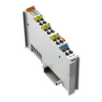
WAGO 750-494/000-001 Manual (134 pages)
3-Phase Power Measurement Module
Brand:
WAGO
| Category:
Control Unit
| Size: 4.77 MB
Table of Contents
Table of Contents
3
1 Notes about this Documentation
6
Validity of this Documentation
6
Table 1: Variants
6
Revision History
7
Copyright
7
Table 2: Revision History
7
Symbols
8
3-Phase Power Measurement Module
9
Number Notation
10
Font Conventions
10
Table 3: Number Notation
10
Table 4: Font Conventions
10
2 Important Notes
11
Legal Bases
11
Subject to Changes
11
Personnel Qualifications
11
Use of the WAGO-I/O-SYSTEM 750 in Compliance with Underlying Provisions
11
Technical Condition of Specified Devices
12
Safety Advice (Precautions)
13
3 Device Description
15
View
16
Figure 1: View
16
Table 5: Legend for Figure "View
16
Connectors
17
Data Contacts/Internal Bus
17
Power Jumper Contacts/Field Supply
17
Figure 2: Data Contacts
17
Cage Clamp
18
Figure 3: CAGE CLAMP ® Connectors
18
Table 6: Legend for Figure "CAGE CLAMP ® Connectors
18
3-Phase Power Measurement Module
18
Display Elements
19
Figure 4: Display Elements
19
Table 7: Legend for Figure "Display Elements
19
Operating Elements
20
Schematic Diagram
21
Figure 5: Schematic Diagram
21
Figure 6: FE Spring Contact
22
3-Phase Power Measurement Module
22
Technical Data
23
Dimensions and Weight
23
Voltage Supply
23
Measuring Inputs
23
Table 8: Technical Data - Dimensions and Weight
23
Table 9: Technical Data - Voltage Supply
23
Table 10: Technical Data - Measuring Inputs
23
Measured Values
24
Table 11: Technical Data - Measured Values
24
Internal Bus Communication
25
Connection Type
25
Table 12: Technical Data - Internal Bus Communication
25
Table 13: Technical Data - Data Contacts
25
Table 14: Technical Data - Field Wiring
25
Climatic Environmental Conditions
26
Table 15: Technical Data - Climatic Environmental Conditions
26
Approvals
27
3-Phase Power Measurement Module
28
Standards and Guidelines
29
4 Function Description
30
Measuring Principle
30
Measured Values
30
Description of Measured Values
32
Figure 7: RMS Value Calculation (Example, Not to Scale)
33
Figure 8: Allocation of Active and Reactive Energy in the 4 Quadrants
34
3-Phase Power Measurement Module
34
Figure 9: 4-Quadrant Display for Active and Reactive Power
37
Measuring Errors and Accuracy
38
Table 16: AC Measuring Errors
38
Figure 10: Input Overdrive (Clipping)
39
5 Process Image
40
Overview of Process Data
40
Output Data
41
Definition of Control Words
41
Definition of Output Data Words
42
Input Data
43
Definition of Status Words
43
3-Phase Power Measurement Module
44
Definition of Input Data Words
46
Process Image Descriptions
49
3-Phase Power Measurement Module
50
Building-Up the Measured Values
54
Collections of Measured Values
55
Collection 007 - DC Measured Values
55
Collection 009 - AC Measured Values
55
Table 17: Measured Values of Collection 007 in the Process Image (PI)
55
Table 18: Measured Values of Collection 009 in the Process Image (PI)
56
3-Phase Power Measurement Module
56
Collection 020 - Harmonics Analysis L1
60
Table 19: Measured Values of Collection 020 in the Process Image (PI)
60
Collection 021 - Harmonics Analysis L2
61
Table 20: Measured Values of Collection 021 in the Process Image (PI)
61
Collection 022 - Harmonics Analysis L3
62
Table 21: Measured Values of Collection 022 in the Process Image (PI)
62
Examples of Calculating the Measured Values from the Process Values
63
3-Phase Power Measurement Module
64
Table 27: Register 35
65
Table 31: Register 39
65
6 Mounting
67
Mounting Sequence
67
Inserting and Removing Devices
68
Inserting the I/O Module
68
Figure 11: Insert I/O Module (Example)
68
Figure 12: Snap the I/O Module into Place (Example)
68
Removing the I/O Module
69
Figure 13: Removing the I/O Module (Example)
69
7 Connect Devices
70
Connecting a Conductor to the CAGE CLAMP
70
Figure 14: Connecting a Conductor to a CAGE CLAMP
70
Voltage Measurement
71
Figure 15: Voltage Measurement
71
Current Measurement
72
Current Measurement on a Motor
72
Figure 16: Current Measurement on a Motor
72
Current Transformers
73
Accuracy
73
Types of Current
73
Overcurrent Limiting Factor FS
73
Protection against Shock Hazard Voltages
74
Additional Measuring Instruments in the Current Path
75
Power Measurement
76
Power Measurement on a Machine
76
Power Measurement on Two Motors Regulated by Frequency Converters
76
Figure 17: Power Measurement on a Machine
76
Figure 18: Power Measurement on Two Motors Regulated by Frequency Converters
77
3-Phase Power Measurement Module
77
8 Commissioning
79
Configuration with WAGO-I/O-CHECK
80
Figure 19: WAGO-I/O-CHECK User Interface, Bus Node with I/O Module
80
Figure 20: „3-Phase Power Measurement" Dialog
81
Figure 21: „Settings" Dialog
82
Application" Tab
83
Figure 22: „Application" Tab
83
Phase L1", "Phase L2", "Phase L3" Tabs
84
Figure 23: „Phase L1" Tab
84
I/O Module" Tab
85
Figure 24: „I/O Module" Tab
86
3-Phase Power Measurement Module
86
Energy" Tab
87
Figure 25: "Energy" Tab
87
Factory Settings" Tab
88
Figure 26: "Factory Settings" Tab
88
Displaying the Measured Values Via WAGO-I/O-CHECK
89
Figure 27: Measured Values - Overview
90
Figure 28: Measured Values - Phases
91
Figure 29: Measured Values - Currents and Voltages
92
3-Phase Power Measurement Module
92
Figure 30: Measured Values - Power
93
Figure 31: Measured Values - Energies
94
Figure 32: Measured Values - DC
95
Figure 33: Measured Values - Harmonics Chart
96
Figure 34: Measured Values - Harmonics Table
97
Figure 35: Measured Values - Recording
98
3-Phase Power Measurement Module
98
9 Diagnostics
99
Table 22: Diagnostics
99
10 Appendix
100
Examples of CSV Data Files
100
Snapshot
100
CSV Data File „Measurement Recording
104
Factory Settings
105
Table 23: Factory Settings
105
3-Phase Power Measurement Module
106
Register Assignment
107
Table 24: Register 4
107
Table 25: Register 5
108
Table 26: Register 32
108
Table 28: Register 36
109
Table 29: Register 37
109
Table 30: Register 38
110
Table 32: Register 40
110
Table 33: Register 41
110
Table 34: Register 43
111
Table 35: Register 44
111
Table 36: Register 45
111
Table 37: Register 46
111
Table 38: Register 47
112
Table 39: Register 48
112
Table 40: Register 49
112
Table 41: Register 50
112
Table 42: Register 51
112
Table 43: Register 52
112
3-Phase Power Measurement Module
112
Parameter Assignment
113
Table 44: Register 53
113
Table 45: Register 54
113
Table 46: Register 55
113
Table 47: Parameter 10
113
Table 48: Parameter 11
113
11 Use in Hazardous Environments
119
Marking Configuration Examples
120
Marking for Europe According to ATEX and IEC-Ex
120
Figure 36: Side Marking Example for Approved I/O Modules According to ATEX and Iecex
120
Figure 37: Text Detail - Marking Example for Approved I/O Modules According to ATEX and Iecex
120
Figure 38: Side Marking Example for Approved Ex I I/O Modules
122
Figure 39: Text Detail - Marking Example for Approved Ex I I/O Modules According to ATEX and Iecex
122
Marking for America According to NEC 500
125
Figure 40: Side Marking Example for I/O Modules According to NEC 500
125
Installation Regulations
126
Special Notes Regarding Explosion Protection
126
Special Notes Regarding ANSI/ISA Ex
128
List of Figures
129
List of Tables
131
Advertisement
Advertisement
Related Products
WAGO 750-494 Series
WAGO 750-494/025-001
WAGO 750-494/025-000
WAGO 750-492/040-001
WAGO 750-495/040-00 Series
WAGO 750-495/040-000
WAGO 750-495/040-001
WAGO 750-495/040-002
WAGO 750-489
WAGO 750-469/000-206
WAGO Categories
I/O Systems
Control Unit
Power Supply
Switch
Controller
More WAGO Manuals
Login
Sign In
OR
Sign in with Facebook
Sign in with Google
Upload manual
Upload from disk
Upload from URL