Sign In
Upload
Manuals
Brands
Teledyne Manuals
Measuring Instruments
200E
Teledyne 200E Manuals
Manuals and User Guides for Teledyne 200E. We have
1
Teledyne 200E manual available for free PDF download: Instruction Manual
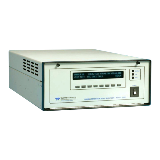
Teledyne 200E Instruction Manual (302 pages)
Chemiluminescence Nitrogen Oxides Analyzer
Brand:
Teledyne
| Category:
Measuring Instruments
| Size: 7.61 MB
Table of Contents
Table of Contents
4
List of Figures
10
M200E Documentation
16
Available Documentation
16
Manual Structure
16
How to Use this Instruction Manual
18
Specifications, Approvals and Warranty
20
M200E Operating Specifications
20
Table 2-1: Model 200E Basic Unit Specifications
20
EPA Equivalency Designation
21
CE Mark Compliance
22
Warranty
22
Getting Started
24
Unpacking and Initial Setup
24
Figure 3-1: Location of Shipping Screws and Power Configuration Plug
25
M200E Layout
26
Figure 3-2: M200E Layout
26
Figure 3-3: M200E Rear Panel Layout
27
Figure 3-4: M200E Front Panel Layout
27
Pneumatic Connections
28
Table 3-1: Inlet / Outlet Connector Nomenclature
28
Span Gas Defined
29
Figure 3-5: Basic Pneumatic Connections for Units Without Valve Options
29
Zero Gas Defined
30
Figure 3-6: Basic Pneumatic Connections for Units with Valve Options
31
Electrical Connections
32
Power Connection
32
Analog Output Connections
32
Figure 3-7: Analog Output Connector
32
Figure 3-8: Status Output Connector
33
Table 3-2: Analog Output Pin-Outs
33
Table 3-3: Status Output Signals
33
Figure 3-9: Control Input Connector
34
Table 3-4: Control Input Signals
34
Ethernet Connection and Configuration
35
Initial Operation
35
Startup
35
Warm-Up
36
Warning Messages
36
Figure 3-10: Front Panel Display During Startup Sequence
36
Table 3-5: Front Panel Display During System Warm-Up
36
Table 3-6: Possible Warning Messages at Start-Up
37
Functional Check
38
Figure 3-11: M200E Pneumatic Diagram in Standard Configuration
39
Figure 3-12: M200E Pneumatic Diagram with Options Installed
40
First Calibration
41
Basic Calibration Procedure
41
Interferences for no Measurements
42
Frequently Asked Questions & Glossary
44
Frequently Asked Questions
44
Glossary
45
Optional Hardware and Software
48
External Pumps (Option 10)
48
Rack Mount Kits (Options 20-23)
48
Current Loop Analog Outputs (Option 41)
48
Particulate Filter Kit (Option 42A)
49
Calibration Valve Options
49
Zero/Span Valves (Option 50)
49
Figure 5-1: Current Loop Option Installed on the Motherboard
49
Internal Zero/Span (IZS) (Option 51)
50
Table 5-1: IZS or Z/S Valve States
50
IZS Permeation Tubes (Options 53 & 55)
51
Table 5-2: Available Permeation Source Options
51
Scrubbers and Expendables
52
Charcoal Scrubber (Option 64A)
52
Charcoal Refill Kit (Part# 00596)
52
Zero Air Scrubber (Option 64B)
52
Zero Air Scrubber Maintenance Kit (Option 43)
52
Table 5-3: Contents of Zero Air Scrubber Maintenance Kit
52
M200E Expendables Kit (Option 42)
53
M200E Spare Parts Kit (Option 43)
53
Communication Options
53
RS232 Modem Cables (Options 60 and 60A)
53
Multidrop (Option 62)
53
Ethernet (Option 63)
53
Sample Gas Conditioners (Options 86 & 88)
54
Figure 5-2: M200E Ethernet Card and Rear Panel with Ethernet Installed
54
Table 5-4: Dryer and NH
54
Manual on CD (Part Number 044100200)
55
Extended Warranty (Options 92 & 93)
55
Operating Instructions
56
Overview of Operating Modes
56
Table 6-1: Analyzer Operating Modes
56
Sample Mode
57
Test Functions
57
Table 6-2: Test Functions Defined
58
Warning Messages
59
Calibration Functions
59
Table 6-3: List of Warning Messages Revision C.4
59
Calibration Mode
60
Setup Mode
60
Password (PASS)
60
Table 6-4: Password Levels
60
Configuration Information (CFG)
62
Clock (CLK)
62
Setup - Range Configuration (RNGE)
63
Figure 6-1: Analog Output Connector Key
63
Physical and Analog Output Ranges
64
Reporting Range Modes
64
Single Range Mode (SNGL)
65
Independent Range Mode (IND)
65
Auto Range Mode (AUTO)
67
Range Units
67
Dilution Ratio
68
Setup - Internal Variables (VARS)
70
Table 6-5: Variable Names (VARS) Revision C.4
70
Setup - Diagnostics (DIAG)
72
Table 6-6: M200E Diagnostic (DIAG) Functions
72
Signal I/O
73
Analog Output Step Test
74
Analog I/O Configuration
75
Table 6-7: DIAG - Analog I/O Functions
75
Table 6-8: Analog Output Voltage Ranges
75
Analog Output Signal Type and Range Selection
76
Table 6-9: Analog Output Current Loop Range
76
Table 6-10: Analog Output Pin Assignments
76
Analog Output Calibration Mode
77
Manual Analog Output Calibration
79
Figure 6-2: Setup for Calibrating Analog Outputs
79
Table 6-11: Voltage Tolerances for Analog Output Calibration
79
Analog Output Offset Adjustment
80
Current Loop Output Adjustment
81
Figure 6-3: Setup for Calibrating Current Outputs
82
AIN Calibration
83
Test Channel Output
83
Table 6-12: Current Loop Output Calibration with Resistor
83
Table 6-13: Test Parameters Available for Analog Output A4
84
Optic Test
85
Electrical Test
85
Ozone Generator Override
86
Flow Calibration
87
Digital Inputs and Outputs
87
Status Outputs
87
Control Inputs
88
Figure 6-4: Status Output Connector
88
Table 6-14: Status Output Pin Assignments
88
Setup - Communication Ports (COMM)
89
Figure 6-5: Control Inputs with Local and External 5 V Power Supply
89
Table 6-15: Control Input Pin Assignments
89
Analyzer ID
90
COM Port Default Settings
90
COM Port Cable Connections
91
COM2 Configuration
91
DTE and DCE Communication
92
COM Port Communication Modes
92
Table 6-16: COM1 and COM2 DB-9 Pin Assignments
92
Table 6-17: COM Port Communication Modes
93
COM Port Baud Rate
95
COM Port Testing
95
Ethernet Port Configuration
96
Table 6-18: Ethernet Status Indicators
96
Hessen Mode Configuration
99
Setup - Data Acquisition System (DAS)
100
Table 6-19: Front Panel LED Status Indicators for Idas
100
Idas Structure
101
Idas Channels
101
Idas Parameters
102
Table 6-20: Idas Data Channel Properties
102
Idas Triggering Events
103
Table 6-21: Idas Data Parameter Functions
103
Configuring the Idas
104
Default M200E Idas Configuration
104
Table 6-22: M200E Default Idas Configuration, Revision C.7
105
Viewing Idas Data and Settings
106
Editing Idas Data Channels
107
Trigger Events
108
Editing Idas Parameters
109
Sample Period and Report Period
110
Number of Records
112
Report Function
113
Compact Report
114
Starting Date
114
Disabling/Enabling Data Channels
114
HOLDOFF Feature
115
Remote Idas Configuration
116
Figure 6-6: APICOM Graphical User Interface for Configuring the Idas
116
Remote Operation of the Analyzer
117
Basic Operation
117
Terminal Operating Modes
117
Figure 6-7: Idas Configuration through a Terminal Emulation Program
117
Help Commands in Terminal Mode
118
Command Syntax
118
Table 6-23: Terminal Mode Software Commands
118
Data Types
119
Table 6-24: Command Types
119
Status Reporting
120
Remote Access by Modem
120
COM Port Password Security
121
APICOM Remote Control Program
122
Figure 6-8: APICOM Remote Control Program Interface
122
Additional Communications Documentation
123
Table 6-25: Serial Interface Documents
123
Calibration Procedures
124
Calibration Preparations
124
Required Equipment, Supplies, and Expendables
124
Zero Air
124
Span Gas Standards
124
Permeation Tubes
125
Calibration Gas Traceability
125
Data Recording Devices
125
Conversion Efficiency
125
Figure 7-1: Gas Supply Setup for Determination of no
126
Manual Calibration
127
Connect Zero Air and Span Gases to the Analyzer
128
Set Expected no and no
128
Span Gas Concentrations
128
Figure 7-2: Setup for Manual Calibration Without Z/S Valve or IZS Option
128
Perform Zero/Span Calibration
129
Calibration Checks
130
Calibration with Zero/Span Valves
130
Calibration with IZS Option
132
Figure 7-3: Pneumatic Connections for Manual Calibration Checks with IZS
132
Calibration Checks with IZS or Zero/Span Valves
134
Figure 7-4: Setup for Manual Calibration Check with Z/S Valve or IZS Option
134
Calibration with Independent or AUTO Ranges
135
Calibration in AUTO Range Mode
135
Independent Range Mode
136
Calibration with Remote Contact Closures
136
Automatic Calibration (Autocal)
137
Table 7-2: Autocal Modes
137
Table 7-3: Autocal Attribute Setup Parameters
137
Table 7-4: Example Auto-Cal Sequence
138
Calibration Quality Analysis
139
Table 7-5: Calibration Data Quality Evaluation
140
Epa Protocol Calibration
142
Calibration of Equipment
142
Table 8-1: Activity Matrix for EPA Calibration Equipment and Supplies
143
Table 8-2: Activity Matrix for Calibration Procedure
143
Gas Phase Titration (GPT)
144
GPT Principle of Operation
144
GPT Calibrator Check Procedure
144
Example GPT Calculation
146
Multipoint Calibration Procedure
147
Zero Calibration
148
Span Calibration
148
Figure 8-1: GPT Calibration System
148
Calibration
149
Calibration Frequency
150
Other Quality Assurance Procedures
150
Table 8-3: Definition of Level 1 and Level 2 Zero and Span Checks
151
Summary of Quality Assurance Checks
152
Short Calibration Checks
152
Table 8-4: Activity Matrix for Data Quality
152
Zero/Span Check Procedures
153
Precision Check
153
Precision Check Procedure
153
Certification of Working Standards
153
Certification Procedures of Working Standards
154
Other Methods of Establishing Traceability
154
References
154
Instrument Maintenance
156
Maintenance Schedule
156
Table 9-1: M200E Preventive Maintenance Schedule
156
Predictive Diagnostics
158
Maintenance Procedures
158
Table 9-2: Predictive Uses for Test Functions
158
Changing the Sample Particulate Filter
159
Figure 9-1: Sample Particulate Filter Assembly
159
Changing the O Dryer Particulate Filter
160
Figure 9-2: Particle Filter on O Supply Air Dryer
160
Changing the Ozone Filter Chemical
161
Figure 9-3: 04419 Ozone Filter Unit
161
Rebuilding the External Sample Pump
162
Changing the Pump and IZS Dust Filters
163
Changing the IZS Permeation Tube
163
Changing the External Zero Air Scrubber
164
Changing the no Converter
165
Figure 9-4: Zero Air Scrubber Assembly
165
Cleaning the Reaction Cell
166
Figure 9-5: no 2 Converter Assembly
166
Figure 9-6: Reaction Cell Assembly
167
Cleaning or Changing Critical Flow Orifices
168
Figure 9-7: Critical Flow Orifice Assembly
168
Checking for Light Leaks
169
Theory of Operation
170
Measurement Principle
170
Chemiluminescence
170
Nox
171
Figure 10-1: M200E Sensitivity Spectrum
171
Chemiluminescence Detection
172
The Photo Multiplier Tube
172
Figure 10-2: no 2 Conversion Principle
172
Optical Filter
173
Auto Zero
173
Figure 10-3: Reaction Cell with PMT Tube
173
Measurement Interferences
174
Direct Interference
174
Third Body Quenching
174
Figure 10-4: Reaction Cell During the Autozero Cycle
174
Table 10-1: List of Interferents
175
Light Leaks
176
Pneumatic Operation
176
Pump and Exhaust Manifold
176
Sample Gas Flow
177
Figure 10-5: External Pump Pack
177
Sample Particulate Filter
178
Table 10-2: M200E Valve Cycle Phases
178
Ozone Gas Air Flow
179
Figure 10-6: Ozone Generator Principle
179
Perma Pure Dryer
180
Figure 10-7: Semi-Permeable Membrane Drying Process
180
Ozone Supply Air Filter
181
Figure 10-8: M200E Perma Pure
181
Ozone Scrubber
182
Flow Rate Control - Critical Flow Orifices
182
Figure 10-9: Location of Flow Control Assemblies
183
Figure 10-10: Flow Control Assembly & Critical Flow Orifice
183
Table 10-3: M200E Gas Flow Rates
184
Pneumatic Sensors
185
Sample Pressure Sensor
185
Vacuum Pressure Sensor
185
O 3 Supply Air Flow Sensor
185
Electronic Operation
186
Figure 10-11: M200E Electronic Block Diagram
186
Cpu
187
Figure 10-12: M200E CPU Board Annotated
187
Disk on Chip
188
Flash Chip
188
Sensor Module, Reaction Cell & PMT
188
Reaction Cell Heating Circuit
188
Photo Multiplier Tube (PMT)
189
PMT Cooling System
189
Figure 10-13: Schematic of Basic PMT Design and Functionality
189
TEC Control Board
190
PMT Preamplifier
190
Pneumatic Sensor Board
191
Figure 10-14: PMT Preamp Block Diagram
191
Relay Board
192
Heater Control
192
Valve Control
192
Status Leds
192
Motherboard
193
A to D Conversion
193
Sensor Inputs
193
Thermistor Interface
194
Analog Outputs
194
External Digital I/O
195
C Data Bus
195
Power-Up Circuit
195
Power Supply/ Circuit Breaker
195
Communications Interface
196
Figure 10-15: Power Distribution Block Diagram
196
Front Panel
197
Display
197
Figure 10-16: M200E Electronic Interface Block Diagram
197
Keypad
198
Front Panel States Led's
198
Display / Keyboard Interface Electronics
198
Table 10-4: Front Panel Status Led's
198
Software Operation
199
Adaptive Filter
199
Figure 10-17: Keyboard and Display Interface Block Diagram
199
Calibration - Slope and Offset
200
Figure 10-18: Schematic of Basic Software Operation
200
Temperature/Pressure Compensation (TPC)
201
Converter Efficiency Compensation
202
Internal Data Acquisition System (Idas)
202
Troubleshooting & Repair
204
General Troubleshooting
204
Warning Messages
205
Fault Diagnosis with Test Functions
205
Figure 11-1: Viewing and Clearing Warning Messages
205
Using the Diagnostic Signal I/O Function
206
Table 11-1: Test Functions - Possible Causes for Out-Of-Range Values
206
Status Led's
207
Motherboard Status Indicator (Watchdog)
207
Figure 11-2: Switching Signal I/O Functions
207
CPU Status Indicator
208
Relay Board and Status Leds
208
Figure 11-3: Motherboard Watchdog Status Indicator
208
Figure 11-4: Relay Board PCA
209
Gas Flow Problems
210
Table 11-2: Relay Board Status Leds
210
Zero or Low Flow Problems
211
Sample Flow Is Zero or Low
211
Ozone Flow Is Zero or Low
212
High Flow
213
Sample Flow Is Zero or Low but Analyzer Reports Correct Flow
213
Calibration Problems
213
Negative Concentrations
213
No Response
214
Unstable Zero and Span
215
Inability to Span - no SPAN Key
215
Inability to Zero - no ZERO Key
216
Non-Linear Response
216
Discrepancy between Analog Output and Display
217
Other Performance Problems
217
Discrepancy between no and no Slopes
217
Excessive Noise
218
Slow Response
218
Auto-Zero Warnings
218
Subsystem Checkout
219
Simple Vacuum Leak and Pump Check
219
Detailed Pressure Leak Check
219
Performing a Sample Flow Check
220
AC Power Configuration
221
DC Power Supply
221
Table 11-3: DC Power Test Point and Wiring Color Code
221
C Bus
222
Keyboard / Display Interface
222
Table 11-4: DC Power Supply Acceptable Levels
222
Relay Board
223
Motherboard
223
A/D Functions
223
Analog Output Voltages
223
Table 11-5: Relay Board Control Devices
223
Status Outputs
224
Control Inputs
224
Table 11-6: Analog Output Test Function - Nominal Values
224
Table 11-7: Status Outputs Check
224
Cpu
225
Communication
225
General RS-232 Troubleshooting
225
Modem or Terminal Operation
226
PMT Sensor
226
PMT Preamplifier Board
226
High Voltage Power Supply
227
Pneumatic Sensor Assembly
227
Reaction Cell Pressure
228
Sample Pressure
228
Ozone Flow
229
Converter
229
Figure 11-5: Pressure / Flow Sensor Assembly
229
Generator
231
IZS Option
231
Box Temperature
231
PMT Temperature
232
Repair Procedures
232
Disk-On-Chip Replacement
232
Flash Chip Replacement or Upgrade
233
O 3 Generator Replacement
233
Sample and Ozone Dryer Replacement
234
PMT Sensor Hardware Calibration
234
Figure 11-6: Pre-Amplifier Board Layout
235
Replacing the PMT, HVPS or TEC
236
Figure 11-7: M200E Sensor Assembly
237
Technical Assistance
238
Appendix A: Software Documentation
240
Figure A-1: Basic Sample Display Menu
241
Appendix
241
Figure A-2: Sample Display Menu - Units with Z/S Valve or IZS Option Installed
242
Figure A-3: Primary Setup Menu (Except Idas)
243
Figure A-4: Secondary Setup Menu (COMM & VARS)
244
Figure A-5: Secondary Setup Menu (DIAG)
245
Figure A-6: Internal Data Acquisition (Idas) Menu
246
Appendix
247
Setup Variables for Serial I/O, Revision C.8
247
APPENDIX A-2: Setup Variables for Serial I/O, Revision
247
Warnings and Test Measurements, Revision C.8
256
M200E Signal I/O Definitions, Revision C.8
258
APPENDIX A-4: M200E Signal I/O Definitions, Revision
258
APPENDIX A-5: M200E Trigger Events and Idas Functions, Revision
261
Terminal Command Designators, Revision C.8
263
APPENDIX A-6: Terminal Command Designators, Revision
263
Appendix B: Spare Parts and Expendables
266
Appendix C: Repair Questionnaire - M200E
272
Appendix D: Diagrams and Schematics
274
Advertisement
Advertisement
Related Products
Teledyne HASTINGS 200 Series
Teledyne 2000A-EU
Teledyne 200A
Teledyne 2000RS
Teledyne 2010A
Teledyne 202 Series
Teledyne HASTINGS Everywhereyoulook 201 Series
Teledyne HASTINGS Everywhereyoulook 203 Series
Teledyne HASTINGS Everywhereyoulook 205 Series
Teledyne HASTINGS Everywhereyoulook 207 Series
Teledyne Categories
Measuring Instruments
Analytical Instruments
Digital Camera
Test Equipment
Laboratory Equipment
More Teledyne Manuals
Login
Sign In
OR
Sign in with Facebook
Sign in with Google
Upload manual
Upload from disk
Upload from URL