Sign In
Upload
Manuals
Brands
Teledyne Manuals
Measuring Instruments
200EM
Teledyne 200EM Manuals
Manuals and User Guides for Teledyne 200EM. We have
1
Teledyne 200EM manual available for free PDF download: Instruction Manual
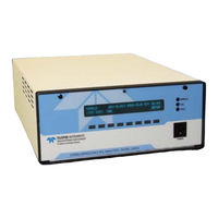
Teledyne 200EM Instruction Manual (338 pages)
NITROGEN OXIDES ANALYZER
Brand:
Teledyne
| Category:
Measuring Instruments
| Size: 7 MB
Table of Contents
Table of Contents
5
M200EH/EM Documentation
15
Using this Manual
15
Specifications, Approvals and Warranty
17
M200EH/EM Operating Specifications
17
Table 2-1: Model 200EH/EM Basic Unit Specifications
17
CE Mark Compliance
18
Warranty
18
Getting Started
21
Unpacking and Initial Setup
21
M200EH/EM Layout
22
Figure
22
Figure
23
Electrical Connections
24
Power Connection
24
Analog Output Connections
25
Figure 3-4: Analog Output Connector
25
Table 3-1: Analog Output Data Type Default Settings
25
Table 3-2: Analog Output Pin-Outs
25
Connecting the Status Outputs
26
Figure 3-5: Status Output Connector
26
Table 3-3: Status Output Signals
26
Connecting the Control Inputs
27
Figure 3-6: Control Input Connector
27
Table 3-4: Control Input Signals
27
Connecting the Serial Ports
28
Connecting to a LAN or the Internet
28
Connecting to a Multidrop Network
28
Pneumatic Connections
29
Figure 3-7: M200EH Internal Pneumatic Block Diagram - Standard Configuration
29
Table 3-5: Inlet / Outlet Connector Nomenclature
29
Calibration Gases
30
Figure 3-8: M200EM Internal Pneumatic Block Diagram - Standard Configuration
30
Table 3-6: NIST-Srm's Available for Traceability of no
31
Pneumatic Connections to M200EH/EM Basic Configuration
32
Figure 3-9: Pneumatic Connections-Basic Configuration-Using Gas Dilution Calibrator
32
Figure 3-10: Pneumatic Connections-Basic Configuration-Using Bottled Span Gas
32
Connections with Internal Valve Options Installed
33
Figure 3-11: Pneumatic Connections-With Zero/Span Valve Option (50)
33
Initial Operation
34
Startup
34
Figure 3-12: Pneumatic Connections-With 2-Span Point Option (52) -Using Bottled Span Gas
34
Figure 3-13: Front Panel Display During Startup Sequence
35
Warm-Up
36
Warning Messages
36
Table 3-7: Front Panel Display During System Warm-Up
36
Table 3-8: Possible Warning Messages at Start-Up
37
Functional Check
38
Calibration
39
Basic no Calibration Procedure
39
Basic O
42
O 2 Calibration Setup
42
Sensor Calibration Procedure
42
O2 Calibration Method
42
Figure 3-14: O 2 Sensor Calibration Set up
42
Interferences for no Measurements
45
Frequently Asked Questions & Glossary
47
Frequently Asked Questions
47
Glossary
48
Optional Hardware and Software
51
External Pumps (OPT 10)
51
Rack Mount Kits (Opts 20-23)
51
Carrying Strap Handle (OPT 29)
52
Figure 5-1: M200EH/EM with Carrying Strap Handle and Rack Mount Brackets
52
Current Loop Analog Outputs (OPT 41)
53
Converting Current Loop Analog Outputs to Standard Voltage Outputs
53
Figure 5-2: Current Loop Option Installed on the Motherboard
53
Particulate Filter Kit (OPT 42A)
54
Ozone Supply Filter (OPT 49)
54
Calibration Valve Options
54
Zero/Span Valves (OPT 50)
54
Figure 5-3: M200EH - Internal Pneumatics with Zero-Span Valve Option 50
55
Figure 5-4: M200EM - Internal Pneumatics with Zero-Span Valve Option 50
55
Second Range Span Valve (OPT 52)
56
Table 5-1: Zero/Span Valve States
56
Table 5-2: Two-Point Span Valve Operating States
57
Figure 5-5: M200EH - Internal Pneumatics with Second Span Point Valve Option 52
58
Oxygen Sensor (OPT 65)
59
Theory of Operation
59
Paramagnetic Measurement of O
59
Figure 5-6: M200EM - Internal Pneumatics with Second Span Point Valve Option 52
59
Operation Within the M200EH/EM Analyzer
60
Pneumatic Operation of the O
60
Sensor
60
Figure 5-7: Oxygen Sensor - Principle of Operation
60
Sensor Option 65
61
Charcoal Scrubber (OPT 64A)
62
Charcoal Refill Kit (Part# 00596)
62
Zero Air Scrubber (OPT 64B)
62
Zero Air Scrubber Maintenance Kit (OPT 43)
62
M200EH/EM Expendables Kit (OPT 42)
62
Table 5-3: Contents of Zero Air Scrubber Maintenance Kit
62
M200EH/EM Spare Parts Kit (OPT 43)
63
Communication Options
63
RS232 Modem Cables (Opts 60 and 60A)
63
Multidrop (OPT 62)
63
Figure 5-10: M200EH/EM Multidrop Card
63
Ethernet (OPT 63)
64
Figure 5-11: M200EH/EM Ethernet Card
64
Figure 5-12: M200EH/EM Rear Panel with Ethernet Installed
64
Sample Gas Conditioners (Opts 86 & 88)
65
Alarm Relay Option (OPT 67)
65
Table 5-4: Dryer and NH
65
Table 5-5: Alarm Relay Output Assignments
65
Figure 5-13: Alarm Relay Output Pin Assignments
66
Table 5-6 Concentration Alarm Relay Output Operation
66
Special Software Features
67
Maintenance Mode Switch
67
Second Language Switch
67
Dilution Ratio Option
67
Additional Manual (OPT 70)
67
Extended Warranty (Opts 92 & 93)
68
Operating Instructions
69
Overview of Operating Modes
69
Figure 6-1: Front Panel Display
69
Table 6-1: Analyzer Operating Modes
70
Sample Mode
71
Test Functions
71
Table 6-2: Test Functions Defined
71
Figure 6-2: Viewing M200EH/EM TEST Functions
72
Warning Messages
73
Figure 6-3: Viewing and Clearing M200EH/EM WARNING Messages
73
Table 6-3: List of Warning Messages Revision F.0
73
Calibration Mode
74
Calibration Functions
74
Setup Mode
75
Table 6-4: Primary Setup Mode Features and Functions
75
Table 6-5: Secondary Setup Mode Features and Functions
75
Setup
76
ACAL: Automatic Calibration
76
Setup
77
DAS - Using the Data Acquisition System (Idas)
77
Table 6-6: Front Panel LED Status Indicators for Idas
77
Idas Structure
78
Idas Channels
78
Table 6-7: Idas Data Channel Properties
78
Idas Parameters
79
Idas Triggering Events
79
Table 6-8: Idas Data Parameter Functions
79
Default Idas Channels
80
Table 6-9: M200EH/EM Default Idas Configuration
81
Viewing Idas Data and Settings
82
Editing Idas Data Channels
83
Trigger Events
84
Editing Idas Parameters
85
Sample Period and Report Period
87
Number of Records
89
Report Function
90
Compact Report
90
Starting Date
90
Disabling/Enabling Data Channels
91
HOLDOFF Feature
91
Remote Idas Configuration
92
Figure 6-4: APICOM Graphical User Interface for Configuring the Idas
92
Figure 6-5: Idas Configuration through a Terminal Emulation Program
93
Setup
94
Range Units
94
Dilution Ratio
95
PASS: Password Feature
96
Table 6-10: Password Levels
96
SETUP CLK: Setting the Internal Time-Of-Day Clock
98
SETUP more COMM: Setting up the Analyser's Communication Ports
100
Analyzer ID
100
COM Port Default Settings
101
COM Port Cable Connections
101
Figure 6-6: Back Panel Connector Pin-Outs for COM1 & COM2 in RS-232 Mode
101
Figure 6-7: CPU Connector Pin-Outs for COM1 & COM2 in RS-232 Mode
102
Configuration of COM2
103
Figure 6-8: CPU Card Locations of RS-232/486 Switches, Connectors and Jumpers
103
DTE and DCE Communication
104
Figure 6-9: Back Panel Connector Pin-Outs for COM2 in RS-485 Mode
104
Figure 6-10: CPU Connector Pin-Outs for COM2 in RS-485 Mode
104
Ethernet Card Configuration
105
Ethernet Card COM2 Communication Modes and Baud Rate
105
Configuring the Ethernet Interface Option Using DHCP
105
Table 6-11: Ethernet Status Indicators
105
Table 6-12: Lan/Internet Configuration Properties
106
Manually Configuring the Network IP Addresses
108
Changing the Analyzer's HOSTNAME
110
Table 6-13: Internet Configuration Keypad Functions
110
Multidrop RS-232 Set up
111
Figure 6-11: Location of JP2 on RS232-Multidrop PCA (Option 62)
111
Figure 6-12: RS232-Multidrop PCA Host/Analyzer Interconnect Diagram
112
COM Port Communication Modes
113
Table 6-14: COMM Port Communication Modes
113
COM Port Baud Rate
115
COM Port Testing
116
VARS: Internal Variables (VARS)
117
Table 6-15: Variable Names (VARS)
117
Setting the Gas Measurement Mode
119
DIAG: Diagnostics MENU
120
Table 6-16: M200EH/EM Diagnostic (DIAG) Functions
120
Accessing the Diagnostic Features
121
Signal I/O
122
Analog Output Step Test
123
ANALOG OUTPUTS and Reporting Ranges
124
Analog Output Signals Available on the M200EH/EM
124
Figure 6-13: Analog Output Connector Key
124
Table 6-17: Analog Output Voltage Ranges with Over-Range Active
124
Table 6-18: Analog Output Pin Assignments
124
Physical Range Versus Analog Output Reporting Ranges
125
Table 6-19: Analog Output Current Loop Range
125
Table 6-20: Example of Analog Output Configuration for M200EH/EM
125
Analog I/O Configuration
127
The Analog I/O Configuration Submenu
127
Table 6-21: DIAG - Analog I/O Functions
127
Analog Output Signal Type and Range Selection
129
Turning the Analog Output Over-Range Feature ON/OFF
130
Adding a Recorder Offset to an Analog Output
131
Assigning an Idas Parameter to an Analog Output Channel
132
Reporting Gas Concentrations Via the M200EH/EM Analog Output Channels
132
Table 6-22: Analog Output Data Type Default Settings
132
Table 6-23: Analog Output Idas Parameters Related to Gas Concentration Data
133
Setting the Reporting Range Scale for an Analog Output
135
Setting Data Update Rate for an Analog Output
137
Turning an Analog Output on or off
138
Analog Output Calibration
139
Automatic Analog Output Calibration
140
Manual Calibration of Analog Output Configured for Voltage Ranges
141
Figure 6-14: Setup for Calibrating Analog Outputs
141
Table 6-24: Voltage Tolerances for Analog Output Calibration
141
Manual Calibration of Analog Outputs Configured for Current Loop Ranges
142
Figure 6-15: Setup for Calibrating Current Outputs
143
Figure 6-16: Alternative Setup for Calibrating Current Outputs
143
Table 6-25: Current Loop Output Calibration with Resistor
144
AIN Calibration
145
Other Diag Menu Functions
146
Display Sequence Configuration
146
Table 6-26: M200EH/EM Available Concentration Display Values
146
Table 6-27: M200EH/EM Concentration Display Default Values
147
Optic Test
149
Electrical Test
150
Ozone Generator Override
151
Flow Calibration
152
SETUP - ALRM: Using the Optional Gas Concentration Alarms (OPT 67)
153
Table 6-28: Concentration Alarm Default Settings
153
Remote Operation of the Analyzer
154
Remote Operation Using the External Digital I/O
154
Status Outputs
154
Figure 6-17: Status Output Connectortable 6-29: Status Output Pin Assignments
154
Control Inputs
155
Table 6-30: Control Input Pin Assignments
155
Remote Operation Using the External Serial I/O
156
Terminal Operating Modes
156
Figure 6-18: Control Inputs with Local 5 V Power Supply
156
Figure 6-19: Control Inputs with External 5 V Power Supply
156
Help Commands in Terminal Mode
157
Command Syntax
157
Table 6-31: Terminal Mode Software Commands
157
Table 6-32: Command Types
157
Data Types
158
Status Reporting
159
Remote Access by Modem
159
COM Port Password Security
161
APICOM Remote Control Program
162
Additional Communications Documentation
162
Figure 6-20: APICOM Remote Control Program Interface
162
Table 6-33: Serial Interface Documents
162
Using the M200EH/EM with a Hessen Protocol Network
163
General Overview of Hessen Protocol
163
Hessen COMM Port Configuration
163
Table 6-34: RS-232 Communication Parameters for Hessen Protocol
163
Selecting a Hessen Protocol Type
164
Setting the Hessen Protocol Response Mode
165
Table 6-28: M200EH/EM Hessen Protocol Response Modes
165
Hessen Protocol Gas ID
166
Table 6-35: M200EH/EM Hessen GAS ID List
166
Setting Hessen Protocol Status Flags
167
Table 6-36: Default Hessen Status Bit Assignments
167
Instrument ID Code
168
Calibration Procedures
169
Calibration Preparations
169
Required Equipment, Supplies, and Expendables
169
Zero Air
169
Span Calibration Gas Standards & Traceability
170
Traceability
170
Table 7-1: NIST-Srm's Available for Traceability of no
170
Data Recording Devices
171
Conversion Efficiency
171
Determining / Updating the no Converter Efficiency
171
Manual Calibration
174
Figure 7-1: Gas Supply Setup for Determination of no Figure 7-2: Pneumatic Connections-With Zero/Span Valve Option (50)
174
Figure 7-3: Pneumatic Connections-With 2-Span Point Option (52) -Using Bottled Span Gas
174
Calibration Checks
177
Manual Calibration with Zero/Span Valves
178
Figure7-4: Pneumatic Connections-With Zero/Span Valve Option (50)
178
Calibration Checks with Zero/Span Valves
181
Calibration with Remote Contact Closures
182
Automatic Calibration (Autocal)
183
Table 7-2: Autocal Modes
183
Table 7-3: Autocal Attribute Setup Parameters
183
Table 7-4: Example Auto-Cal Sequence
184
Calibration Quality Analysis
186
Table 7-5: Calibration Data Quality Evaluation
186
EPA Protocol Calibration
187
Instrument Maintenance
189
Maintenance Schedule
189
Table 9-1: M200EH/EM Preventive Maintenance Schedule
190
Predictive Diagnostics
191
Maintenance Procedures
191
Table 9-2: Predictive Uses for Test Functions
191
Changing the Sample Particulate Filter
192
Figure 9-1: Sample Particulate Filter Assembly
192
Changing the Odryer Particulate Filter
193
Figure 9-2: Particle Filter on O Supply Air Dryer
193
Changing the Ozone Filter Chemical
194
Figure 9-3: 04419 Ozone Filter Unit
194
Rebuilding the External Sample Pump
196
Changing the Pump and IZS Dust Filters
196
Changing the External Zero Air Scrubber
197
Figure 9-4: Zero Air Scrubber Assembly
197
Changing the no Converter
198
Figure 9-5: no Converter Assembly
198
Cleaning the Reaction Cell
199
Figure 9-6: Reaction Cell Assembly
199
Changing Critical Flow Orifices
200
Checking for Light Leaks
201
Figure 9-7: Critical Flow Orifice Assembly
201
Theory of Operation
203
Measurement Principle
203
Chemiluminescence
203
And no Determination
204
Figure 10-1: M200EH/EM Sensitivity Spectrum
204
Chemiluminescence Detection
205
The Photo Multiplier Tube
205
Figure 10-2: no 2 Conversion Principle
205
Optical Filter
206
Auto Zero
206
Figure 10-3: Reaction Cell with PMT Tube
206
Measurement Interferences
207
Direct Interference
207
Third Body Quenching
207
Figure 10-4: Reaction Cell During the Autozero Cycle
207
Light Leaks
208
Converter
208
Table 10-1: List of Interferents
208
Pneumatic Operation
209
Pump and Exhaust Manifold
209
Figure 10-5: External Pump Pack
209
Sample Gas Flow
210
NO and Autozero Cycles
210
Table 10-2: M200EH/EM Valve Cycle Phases
210
Flow Rate Control - Critical Flow Orifices
211
Figure 10-6: Location of Gas Flow Control Assemblies for M200EH
211
Figure 10-7: Location of Gas Flow Control Assemblies for M200EM
212
Figure 10-8: Location of Gas Flow Control Assemblies for M200EH with O
212
Critical Flow Orifice
213
Figure 10-9: Location of Gas Flow Control Assemblies for M200EH with Second Span Point Option 52
213
Figure 10-10: Flow Control Assembly & Critical Flow Orifice
214
Table 10-3: M200EH/EM Critical Flow Orifice Diameters and Gas Flow Rates
214
Sample Particulate Filter
215
Ozone Gas Air Flow
215
O3 Generator
216
Figure 10-11: Ozone Generator Principle
216
Perma Pure ® Dryer
217
Figure 10-12: Semi-Permeable Membrane Drying Process
217
Figure 10-13: M200EH/EM Perma Pure ® Dryer
218
Ozone Supply Air Filter
219
Ozone Scrubber
219
Pneumatic Sensors
220
Vacuum Manifold
220
Sample Pressure Sensor
220
Figure 10-14: Vacuum Manifold
220
Vacuum Pressure Sensor
221
O 3 Supply Air Flow Sensor
221
Dilution Manifold
221
Figure 10-15: Dilution Manifold
222
Electronic Operation
223
Figure 10-16: M200EH/EM Electronic Block Diagram
223
Cpu
224
Figure 10-17: M200EH/EM CPU Board Annotated
224
Disk on Chip
225
Flash Chip
225
Sensor Module, Reaction Cell
225
Reaction Cell Heating Circuit
225
Photo Multiplier Tube (PMT)
226
Figure 10-18: PMT Housing Assembly
226
Figure 10-19: Basic PMT Design
226
PMT Cooling System
227
TEC Control Board
227
Figure 10-20: PMT Cooling System
227
PMT Preamplifier
228
Figure 10-21: PMT Preamp Block Diagram
228
Pneumatic Sensor Board
229
Relay Board
229
Relay PCA Location and Layout
229
Heater Control
229
Figure 10-22: Heater Control Loop Block Diagram
229
Thermocouple Inputs and Configuration Jumper (JP5)
230
Figure 10-23: Thermocouple Configuration Jumper (JP5) Pin-Outs
230
Table 10-4: Thermocouple Configuration Jumper (JP5) Pin-Outs
230
Valve Control
231
Table 10-5: Typical Thermocouple Settings for M200E Series Analyzers
231
Status Leds & Watch Dog Circuitry
232
Watchdog Indicator (D1)
232
Figure 10-24: Status LED Locations - Relay PCA
232
Motherboard
233
A to D Conversion
233
Sensor Inputs
233
Thermistor Interface
234
Analog Outputs
234
External Digital I/O
235
I 2 C Data Bus
235
Power-Up Circuit
235
Power Distribution &Circuit Breaker
236
Figure 10-25: Power Distribution Block Diagram
236
Communications Interface
237
Figure 10-26: Interface Block Diagram
237
Front Panel Interface
238
Analyzer Status Led's
238
Keyboard
238
Figure 10-27: M200EH/EM Front Panel Layout
238
Table 10-6: Front Panel Status Led's
238
Display
239
Keyboard/Display Interface Electronics
239
Figure 10-28: Keyboard and Display Interface Block Diagram
239
Software Operation
241
Figure 10-29: Schematic of Basic Software Operation
241
Adaptive Filter
242
Calibration - Slope and Offset
242
Temperature/Pressure Compensation (TPC)
243
Internal Data Acquisition System (Idas)
244
Converter Efficiency Compensation
244
Troubleshooting & Repair
245
General Troubleshooting
245
Warning Messages
246
Fault Diagnosis with Test Functions
246
Figure 11-1: Viewing and Clearing Warning Messages
246
Using the Diagnostic Signal I/O Function
247
Table 11-1: Test Functions - Possible Causes for Out-Of-Range Values
247
Figure 11-2: Switching Signal I/O Functions
248
Status Led's
249
Motherboard Status Indicator (Watchdog)
249
CPU Status Indicator
249
Relay Board and Status Leds
249
Figure 11-3: Motherboard Watchdog Status Indicator
249
Figure 11-4: Relay Board PCA
250
Table 11-2: Relay Board Status Leds
251
Gas Flow Problems
252
M200EH Internal Gas Flow Diagrams
252
Figure 11-5: M200EH - Basic Internal Gas Flow
252
Figure 11-6: M200EH - Internal Gas Flow with OPT 50
253
Figure 11-7: M200EH - Internal Gas Flow with OPT 52
253
Figure 11-8: M200EH - Internal Gas Flow with OPT 65
254
Figure 11-9: M200EH - Internal Gas Flow with OPT 50 + OPT 65
254
M200EM Internal Gas Flow Diagrams
255
Figure 11-10: M200EM - Basic Internal Gas Flow
255
Figure 11-11: M200EM - Internal Gas Flow with OPT 50
255
Figure 11-12: M200EM - Internal Gas Flow with OPT 52
256
Figure 11-13: M200EM - Internal Gas Flow with OPT 65
256
Zero or Low Flow Problems
257
Sample Flow Is Zero or Low
257
Figure 11-14: M200EM - Internal Gas Flow with OPT 50 + OPT 65
257
Ozone Flow Is Zero or Low
258
High Flow
259
Sample Flow Is Zero or Low but Analyzer Reports Correct Flow
259
Calibration Problems
260
Negative Concentrations
260
No Response
260
Unstable Zero and Span
261
Inability to Span - no SPAN Key
261
Inability to Zero - no ZERO Key
262
Non-Linear Response
262
Discrepancy between Analog Output and Display
263
Other Performance Problems
263
Discrepancy between no and NOX
263
Discrepancy between no and no Slopes
263
Excessive Noise
263
Slow Response
263
Auto-Zero Warnings
264
Subsystem Checkout
265
Simple Vacuum Leak and Pump Check
265
Detailed Pressure Leak Check
265
Performing a Sample Flow Check
266
AC Power Configuration
267
Figure 11-15: Location of AC Power Configuration Jumpers
267
AC Configuration - Internal Pump (JP7)
268
Figure 11-16: Pump AC Power Jumpers (JP7)
268
Table 11-3: AC Power Configuration for Internal Pumps (JP7)
268
AC Configuration - Standard Heaters (JP2)
269
Figure 11-17: Typical Set up of AC Heater Jumper Set (JP2)
269
Table 11-4: Power Configuration for Standard AC Heaters (JP2)
269
AC Configuration -Heaters for Option Packages (JP6)
270
Figure 11-18: Typical Set up of AC Heater Jumper Set (JP2)
270
Table 11-5: Power Configuration for Optional AC Heaters (JP6)
270
DC Power Supply Test Points
271
I 2 C Bus
271
Table 11-6: DC Power Test Point and Wiring Color Code
271
Table 11-7: DC Power Supply Acceptable Levels
271
Keyboard / Display Interface
272
Genreal Relay Board Diagnostic
272
Table 11-8: Relay Board Control Devices
272
Motherboard
273
A/D Functions
273
Analog Output Voltages
273
Table 11-9: Analog Output Test Function - Nominal Values
273
Status Outputs
274
Figure 11-19: Typical Set up of Status Output Test
274
Table 11-10: Status Outputs Pin Assignments
274
Control Inputs
275
Cpu
275
Communication
276
General RS-232 Troubleshooting
276
Modem or Terminal Operation
276
PMT Sensor
277
PMT Preamplifier Board
277
High Voltage Power Supply
277
Table 11-11: Example of HVPS Power Supply Outputs
277
Pneumatic Sensor Assembly
278
Reaction Cell Pressure
278
Sample Pressure
278
Figure 11-20: Pressure / Flow Sensor Assembly
278
Ozone Flow
279
Converter
279
Generator
280
Box Temperature
280
PMT Temperature
280
Repair Procedures
281
Disk-On-Chip Replacement
281
Flash Chip Replacement or Upgrade
282
O 3 Generator Replacement
282
Sample and Ozone Dryer Replacement
283
PMT Sensor Hardware Calibration
284
Figure 11-22: Pre-Amplifier Board Layout
284
Replacing the PMT, HVPS or TEC
285
Figure 11-22: M200EH/EM Sensor Assembly
286
Removing / Replacing the Relay PCA from the Instrument
288
Figure 11-23: Relay PCA with AC Relay Retainer in Place
288
Figure 11-24: Relay PCA Mounting Screw Locations
288
Technical Assistance
289
A Primer on Electro-Static Discharge
291
How Static Charges Are Created
291
Figure 12-1: Triboelectric Charging
291
Table 12-1: Static Generation Voltages for Typical Activities
291
How Electro-Static Charges Cause Damage
292
Common Myths about ESD Damage
293
Basic Principles of Static Control
293
General Rules
294
Figure 12-2: Basic Anti-ESD Work Station
294
Basic Anti-ESD Procedures for Analyzer Repair and Maintenance
295
Working at the Instrument Rack
295
Working at an Anti-ESD Work Bench
295
Transferring Components from Rack to Bench and Back
296
Opening Shipments from Teledyne Instruments Customer Service
296
Packing Components for Return to Teledyne Instruments Customer Service
297
Advertisement
Advertisement
Related Products
Teledyne HASTINGS 200 Series
Teledyne 2000A-EU
Teledyne 200E
Teledyne 200A
Teledyne 2000RS
Teledyne 200EH
Teledyne 200EU
Teledyne 202 Series
Teledyne HASTINGS Everywhereyoulook 201 Series
Teledyne HASTINGS Everywhereyoulook 203 Series
Teledyne Categories
Measuring Instruments
Analytical Instruments
Digital Camera
Test Equipment
Laboratory Equipment
More Teledyne Manuals
Login
Sign In
OR
Sign in with Facebook
Sign in with Google
Upload manual
Upload from disk
Upload from URL