Sign In
Upload
Manuals
Brands
Teledyne Manuals
Measuring Instruments
2000RS
Teledyne 2000RS Conductivity Analyzer Manuals
Manuals and User Guides for Teledyne 2000RS Conductivity Analyzer. We have
1
Teledyne 2000RS Conductivity Analyzer manual available for free PDF download: Operating Instructions Manual
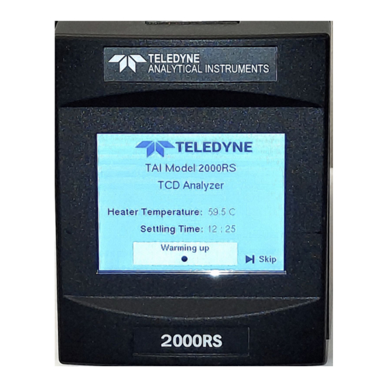
Teledyne 2000RS Operating Instructions Manual (125 pages)
Thermal Conductivity Analyzer
Brand:
Teledyne
| Category:
Measuring Instruments
| Size: 5 MB
Table of Contents
Safety Messages
6
Table of Contents
9
Introduction
14
Overview
14
Typical Applications
14
Main Features of the Analyzer
15
Model Designations
16
Front Panel (Operator Interface)
16
Figure 1-1: Model 2000RS Front Panel
16
Front Access Door
17
Figure 1-2: Model 2000RS 19" Relay Rack
17
Rear Panel (Equipment Interface)
18
Figure 1-3: Model 2000RS Rear Panel (Sealed Air Option)
18
Operational Theory
20
Sensor Theory
20
Principles of Operation
20
Calibration
21
Figure 2-1: Thermal Conductivity Cell Operating Principle
21
Effects of Flowrate and Gas Density
22
Measurement Results
22
Electronics and Signal Processing
22
Figure 2-2: Block Diagram of the Model 2000RS
23
Figure 2-3: 2000RS Internal Electronic Component Location
25
Installation
26
Unpacking the Analyzer
26
Mounting the Analyzer
26
Rear Panel Connections
27
Figure 3-1: 20000RS Single Cover with Feet
27
Figure 3-2: Rear Panel of the Model 2000RS (Auto Cal Option)
27
Gas Connections
28
1Sample System Design
28
Pressure and Flowrate Regulation
28
VENT Exhaust
29
SAMPLE Gas
29
REFERENCE Gas
29
ZERO Gas
30
SPAN Gas
30
Testing the System
31
Warm up at Power up
31
Electrical Connections
32
24VDC Input Power
32
50-Pin Equipment Interface Connector
32
Figure 3-3: Equipment Interface Connector Pin Arrangement
32
Table 3-1: Analog Output Connections Pin Function
33
Table 3-2: Alarm Relay Contact Pins
34
Table 3-3: Remote Calibration Connections
35
Figure 3-4: Remote Probe Connections
37
Figure 3-5: FET Series Resistance
37
Port
38
Table 3-5: Commands Via RS-232 Input
38
Profibus
39
Operation
40
Introduction
40
Start up Screens
41
Figure 4-1: Analyze Screen Display (Startup)
41
Diagnostic Screen
42
Figure 4-2: Analyze Screen Display (Warmup)
42
Figure 4-1: Analyze Screen Display (Screen 1)
43
Figure 4-1: Analyze Screen Display (Screen2)
43
Main Screen
44
Figure 4-5: Analyze Screen Display (Details)
44
Menu Screen
48
System Screen
49
Password
50
Logout
53
Auto Cal Screen
54
Self Test
59
Application
59
Algorithm
67
Cal Independent
73
Range Polarity
74
VB Baud Rate Screen
75
Profibus Screen
76
11Analog Output
82
Range Identification
83
Concentration
84
Ma Calibration
84
More Screen
86
Version
87
System Status
87
Firmware Upgrade
89
Factory Reset
90
The Range Function
90
Alarm Function
93
Alarm Setpoint
97
HI/LOW Alarm
97
Alarm Defeat
97
Failsafe/Non-Failsafe Mode
98
Latching/Non-Latching Alarm
98
Alarm Status
99
The Zero and Span Functions
99
Zero Cal
100
Auto Mode Zeroing
101
Manual Mode Zeroing
104
Span Cal
105
Auto Mode Spanning
106
Span Manual Mode Run Screen
110
Routine Maintenance
111
System Self Diagnostic Test
111
Major Internal Components
112
Figure 5-3: Rear Panel Removal
113
Cleaning
114
Troubleshooting
114
Appendix
116
Model 2000RS Specifications
116
Recommended 2-Year Spare Parts List
117
Drawing List
119
Application Notes
119
Advertisement
Advertisement
Related Products
Teledyne HASTINGS 200 Series
Teledyne 2000A-EU
Teledyne 200E
Teledyne 200A
Teledyne 200EH
Teledyne 200EM
Teledyne 200EU
Teledyne 202 Series
Teledyne HASTINGS Everywhereyoulook 201 Series
Teledyne HASTINGS Everywhereyoulook 203 Series
Teledyne Categories
Measuring Instruments
Analytical Instruments
Test Equipment
Digital Camera
Laboratory Equipment
More Teledyne Manuals
Login
Sign In
OR
Sign in with Facebook
Sign in with Google
Upload manual
Upload from disk
Upload from URL