Sign In
Upload
Manuals
Brands
KEB Manuals
Circuit breakers
COMBIVERT S6 Series
KEB COMBIVERT S6 Series Manuals
Manuals and User Guides for KEB COMBIVERT S6 Series. We have
9
KEB COMBIVERT S6 Series manuals available for free PDF download: Programming Manual, Instructions For Use Manual, Installation Manual, Installation Instructions
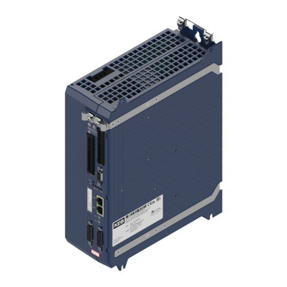
KEB COMBIVERT S6 Series Programming Manual (544 pages)
Brand:
KEB
| Category:
Servo Drives
| Size: 12 MB
Table of Contents
Preface
3
Signal Words and Symbols
3
More Symbols
3
Laws and Guidelines
4
Warranty
4
Support
4
Copyright
4
Table of Contents
5
Basic Safety Instructions
14
Target Group
14
Validity of this Manual
15
Electrical Connection
16
Start-Up and Operation
16
Product Description
17
Product Features
17
Functional Overview
17
Used Terms and Abbreviations
18
Table 3-1: Used Terms and Abbreviations
19
Motion Control
20
State Machine
20
Figure 1: State Machine
20
Changes of the State Machine
23
Control Word
24
Statusword
26
Display of the Actual State
27
Affect the Behaviour of the State Machine
28
Brake Control
30
Specification Brake Control F6-A / S6-A or F6-P S6-P
30
Specification Brake Control F6-K / S6-K
30
Functionality
31
Figure 2: Function Brake Control
31
Characteristics of the Brake Control
32
Influence of the Brake Control on the State Machine
35
Times of the Brake Control
35
Status of the Brake Control
35
Errors and Warnings
37
Errors
37
Figure 3: Process of a Fault Reaction
46
Figure 4: Example Co63
49
Automatic Reset of Errors
50
Warnings
51
Protection Functions
54
Overload (OL)
54
Figure 5: OL-Counter
54
Figure 6: Overload Characteristic
55
Overload Power Components (OL2)
56
Figure 7: Overload (OL2) Limiting Characteristic
57
Figure 8: Increase OL2 for 60A Rated Current and 40°C
59
Figure 9: Characteristic of the Current Limit in Relation to the Time
61
Overtemperature Heatsink (OH)
62
Figure 10: Overtemperature Heatsink (OH)
63
Overtemperature Unit (OHI)
64
Overtemperature Motor (Doh)
65
Figure 11: Sensor Calculation by Excel
67
Motor Protection Switch OH2
68
Figure 12: Tripping Motor Protection Switch
69
Figure 13: Dependence of the Motor Protection Function
70
Figure 14: Dependence of the Tripping Time
70
Figure 15: Determination of the Motor Protection Function Data from the Characteristics of the
71
Fieldbus Watchdog
72
Maximum Current
73
Effective Motor Load
74
Figure 16: Effective Motor Load
74
Maximum Acceleration or Deceleration
75
Monitor the Speed Difference
75
External Error / Warning Triggering
77
Safety Stop from Safety Module
77
Error Underpotential (up / Puready)
78
Overvoltage
82
Table 4-1: Overvoltage Level
82
Table 4-2: Permanent Damage Due to Overvoltage
82
Overspeed (ERROR Overspeed / ERROR Overspeed (EMF))
83
Encoder Monitoring
84
Limit Switch
85
Input Phases Failure Detection
88
Figure 17: Limit Switch
88
Motor Phase Failure Detection
89
UPS Mode (Not Available for Compact Cards)
92
Power off Function
92
Figure 18: Motor Operation
93
Figure 19: Regenerative Operation
94
Figure 20: Motor Operation Without Power-Off Function
94
Figure 21: Regenerative Operation in Case of Mains Power Failure
95
Figure 22: Control to Constant DC Link Voltage
95
Figure 23: Circuit Diagram of the DC Control (Ppz=Number of Pole Pairs)
100
Minimum Switch-Off Times
101
Blockade Handling
103
Monitoring of the Load
108
Quickstop
113
Minimum Current Monitoring in the Safety Module
113
Figure 24: Minimum Current Course
115
Braking Transistor
116
Braking Transistor Handling
116
Table 4-3: Switching Threshold for Braking Transistor
117
Braking Transistor Protective Functions
119
Power and Temperature Calculation at the Braking Resistor
120
Sub-Mounted Braking Resistor Protection
121
Fan Control
123
Fan Control F6
123
Fan Control S6-A / S6-K
124
Terminals Short Circuit Protection
124
Control Type K
124
Control Type a
124
Control Type P
125
Operating Modes
126
Operating Mode 1: Profile Position Mode
127
Figure 25: Profile Positioning Mode (1)
128
Figure 26: Profile Positioning Mode (2)
129
Figure 27: Single Positioning
129
Figure 28: Multi Positioning
130
Figure 29: Restart of a Positioning
130
Figure 30: Ramps in Profile Position Mode
136
Figure 31: Motor Encoder with Initiator at Rotary Table
140
Figure 32: Motor Encoder with Encoder and Initiator at Rotary Table
141
Figure 33: Operation with Motor Model and Encoder with Initiator at Rotary Table
141
Operating Mode 2: Velocity Mode
142
Figure 34: Velocity Mode - Overview
142
Figure 36: Target Speed Limitation
143
Figure 37: Ramp Generator
144
Figure 38: S-Curve Type = 0: Continuous S-Curve
148
Figure 39: S-Curve Type = 4: Abort in S-Curve
148
Figure 40: Pass Zero Type = 0: Not Zero
149
Figure 41: Pass Zero Type = 8: Zero
149
Figure 42: Calculation Example
150
Operating Mode 6: Homing Mode
151
Figure 43: Homing - Method 1
154
Figure 44: Homing - Method 2
155
Figure 45: Homing - Method 3 and 4
155
Figure 46: Homing - Method 5 and 6
156
Figure 47: Homing - Method 7 to 14 (23 to 26)
157
Figure 48: Homing - Method 33 and 34
158
Cyclic Referencing
161
Operating Mode 8: Cyclic Synchronous Position Mode
163
Figure 49: Cyclic Synchronous Position Mode - Overview
163
Figure 50: Cyclic Synchronous Position Mode
164
Figure 51: Example Interpolation
165
Figure 52: Position Precontrol
167
Operating Mode 9: Cyclic Synchronous Velocity Mode
168
Figure 53: Cyclic Synchronous Velocity Mode - Principle
168
Figure 54: Cyclic Synchronous Velocity Mode
169
Operating Mode 10: Cyclic Synchronous Torque Mode
172
Figure 55: Cyclic Synchronous Torque Mode - Overview
172
Figure 56: Transfer Torque Setpoint Telegram -> Current Controller
176
Figure 57: Torque Control and Overspeed Interception
177
Operating Mode -2: Jog Mode in the CM Customer Modes Group
178
Figure 58: Operating Mode Jog Mode
178
Figure 59: Drive Profiles in Jog Mode
182
Operating Mode-Independent Functions
184
Figure 60: Torque Limit in All Quadrants
185
Synchronisation
187
Synchronous Time
187
Optimizing the PLL
188
Display Parameters
189
Overview of the Ru Parameters
189
Speed Displays
193
Figure 61: Auxiliary Representation for the Calculation of Ru83[]
194
Position Displays
195
DC Link Displays
196
Current Displays
196
Torque Displays
196
Power/Energy Displays
197
Status Displays
198
Ru75 Global Drive State
198
Ru76 Drive State
202
De115 Global Drive State Mask
205
Figure 35: Velocity Mode
205
Ru30 SACB Comm State
206
Operating Hours Counter
208
Real Time Clock
208
System Counter
208
5.10 Error Displays and Counter
209
Error / Warning Displays
209
Error Counter
209
Error Memory
210
5.11 Inverter Data
211
Product Code
212
Device Type, Software Version and Date
213
Power Unit Identification
215
Serial Numbers
216
Motor Control
217
Interface to the Encoder
217
Terms and Definitions Used here
217
Encoder Types
218
Figure 62: Order Designation
220
Figure 63: Structure Data Word Biss
222
Table 6-1: Selection of Tested Encoders
224
Position Resolution of Different Encoder Types
228
Scan Time Snd Speed Fluctuations
230
Status Parameters of the Encoder Interface and Encoder
232
Parameters for the Encoder Adjustment
233
Figure 64: Distance-Coded Reference Marks at Heidenhain
240
Figure 65: Distance-Coded Reference Marks
241
Operation of Absolute Linear Encoders
251
Operation of Non-Absolute Linear Encoders (with and Without Reference Marks))
254
Operation of Endat Multiturn Encoders with Battery Buffering
255
Error and Warning Messages
256
Store Data in the Encoder
264
Encoder Serial Number
266
Assignment of the Encoder Channels
267
Motor Parameterization
268
General
268
Asynchronous Motor
270
Figure 66: Equivalent Circuit Diagram Motor
271
Synchronous Motor
278
Figure 67: Equivalent Circuit Diagram Synchronous Motor
279
Structure Overview
295
Figure 68: Structure Overview Motor Model
295
Magnetizing Current
299
Figure 69: Generation of the Magnetizing Current
300
Figure 70: Generation of the D-Component
301
Current Control
304
Measurement / Model Currents
307
Currentlimitations
309
Torque Adjustment
310
Figure 71: Procedure of the Offset Measurement
313
Figure 72: Simplified Representation of the Torque Offset Compensation
317
Field Weakening
318
Figure 73: Field Weakening Range Asynchronous Motor
319
Figure 74: Maximum Voltage Controller
321
Figure 75: Limit Value at Synchronous Motors
322
Figure 76: Maximum Torque Depending on the DC Link Voltage for the Synchronous Motor
324
Figure 77: Adjustment of the Torque Limiting Characteristic
325
Figure 78: Limit Characteristic Curve
327
Figure 79: Safety Distance to the Limit Characteristic
328
Flux Controller (ASM)
329
Figure 80: Flux Controller (ASM)
329
Adaption
330
Saturation Characteristic (SM)
331
Figure 81: Torque Constant Depending on the Active Current
332
Cogging Torque Compensation (SM)
334
Control Mode (with Encoder / Encoderless)
335
Figure 82: Cogging Torque Compensation
335
Figure 83: V/F - Influence of the Additional Setpoint
341
Figure 84: V/F - Influence of the DC Link Voltage Compensation
342
Figure 85: V/F - Influence of the Maximum Degree of Modulation
342
Figure 86: V/F - Influence of Dr48 V/F Characteristic Mode
343
Model Control (ASM and SM)
345
Figure 87: Model Deactivation Depending on the Motor Type
348
Figure 88: Model Deactivation Depending on the Motor Type
349
Figure 89: Model Deactivation Depending on the Motor Type
350
Figure 90: Torque Limit Depending on the Setpoint Value
353
Figure 91: Stabilisation Current Depending on Speed
354
Figure 92: Model Stabilisation Term Depending on Motor Speed
355
DC Link Voltage Compensation
357
Identification
358
Deadtime Compensation
367
Switching Frequency Adjustment and Derating
372
Interrupt Structure of the Software
374
Figure 93: Time Allocation
374
Hardware/Software Current Control
380
Sinus Filter
380
Figure 94: Connection Example Sinus Filter
381
Speed Search
386
Protection Functions (Ramp Stop, Current Limitation in Open-Loop (V/F) Operation)
386
DC Braking
389
Figure 95: Motor De-Excitation Time ASCL
393
Speed Controller
395
Overview
395
Figure 96: Speed Controller Overview
395
PI-Speed Controller
396
Figure 97: Pi-Speed Controller
396
Variable Proportional Factor ((System Deviation)
398
Figure 98: Variable Proportional Factor
398
Variable Proportional/Integral Factor (Speed)
399
Figure 99: Variable Proportional Factor (Kp) / Integral Factor (Ki) with Cs08=10%, Cs09=20
399
Speed Controller Adjustment Via Process Data
400
Determination of the Mass Moment of Inertia
401
Figure 100: High-Run Test with COMBIVIS
401
Speed Controller PT1 Output Filter
402
Figure 101: PT1 Output Filter
402
Torque Precontrol
403
Figure 102: Torque Precontrol Mode 1
403
Figure 103: Torque Precontrol Mode 2
404
Figure 104: Torque Precontrol Smoothing
405
Figure 105: Not Linear Torque Precontrol
407
Speed Setpoint Deceleration
410
Figure 106: Overshoots in the Speed Setpoint
410
Figure 107: Speed Setpoint Deceleration
410
Figure 108: Optimal Precontrol Behaviour
411
Torque Limits
412
Physical Torque Limits
412
Figure 109: Torque Limit in the Lower Speed Range
412
Application-Dependent Torque Limits
413
Position Control
415
Position Values
415
Figure 110: Position Control Overview
416
Advertisement
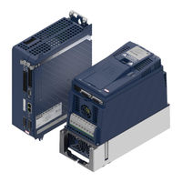
KEB COMBIVERT S6 Series Instructions For Use Manual (82 pages)
Brand:
KEB
| Category:
Controller
| Size: 5 MB
Table of Contents
Preface
3
Signal Words and Symbols
3
More Symbols
3
Laws and Guidelines
4
Warranty and Liability
4
Support
4
Copyright
4
Table of Contents
5
List of Figures
9
List of Tables
10
Glossary
11
Standards for Drive Converters / Control Cabinets
13
Product Standards that Apply Directly to the Drive Converter
13
Basic Standards to Which Drive Converter Standards Refer Directly
13
Standards that Are Used in the Environment of the Drive Converter
14
1 Basic Safety Instructions
15
Target Group
15
Transport, Storage and Proper Use
15
Installation
16
Electrical Connection
17
EMC-Compatible Installation
18
Voltage Test
18
Insulation Measurement
18
Start-Up and Operation
19
Maintenance
20
Repair
21
Disposal
21
2 Product Description
22
Specified Application
22
Residual Risks
22
Unintended Use
22
Product Features
23
Type Code
24
Table 1: Type Code
24
Nameplate
25
Figure 1: Nameplate
25
Configurable Options
26
Table 2: Configurable Options
26
3 Technical Data
27
Operating Conditions
27
Climatic Environmental Conditions
27
Table 3: Climatic Environmental Conditions
27
Mechanical Environmental Conditions
28
Chemical / Mechanical Active Substances
28
Table 4: Mechanical Environmental Conditions
28
Table 5: Chemical / Mechanical Active Substances
28
Electrical Operating Conditions
29
Device Classification
29
Electromagnetic Compatibility
29
Table 6: Device Classification
29
Table 7: Electromagnetic Compatibility
29
Dimensions and Weights
30
Built-In Version
30
Figure 2: Dimensions Built-In Version Housing 2
30
Control Cabinet Installation
31
Figure 3: Mounting Distances
31
Figure 4: Control Cabinet Ventilation
31
Mounting Instructions for Control Cabinet Installation
32
Table 8: Mounting Instructions for Control Cabinet Installation
32
Figure 5: Installation Depth
33
Installation Depth
33
Device Data of the 400 V Devices
34
Overview of the 400 V Devices
34
Rated Operation
34
Table 9: Overview Device Data of the 400 V Devices
34
Voltage And Frequency Specifications Of The 400 V Devices
35
Example for the Calculation of the Motor Voltage
35
Table 10: Input Voltages and Frequencies of the 400 V Devices
35
Table 11: Input Voltages for DC Operation of the 400 V Devices
35
Table 12: Output Voltages and Frequencies of the 400 V Devices
35
Table 13: DC Switching Level 400 V Devices
35
Table 14: Example for the Calculation of the Motor Voltage
35
Input and Output Currents / Overload of the 400 V Devices
36
Table 15: Input Currents of the 400 V Devices
36
Table 16: Output Currents of the 400 V Devices
36
Device Data of the 230 V Devices
37
Overview of the 230 V Devices
37
Rated Operation
37
Table 17: Overview Device Data of the 230 V Devices
37
Voltage And Frequency Specifications Of The 230 V Devices
38
Table 18: Input Voltages and Frequencies of the 230 V Devices
38
Table 19: Input Voltages for DC Operation of the 230 V Devices
38
Table 20: Output Voltages and Frequencies of the 230 V Devices
38
Table 21: DC Switching Level of the 230 V Devices
38
Input and Output Currents / Overload of the 230 V Devices
39
Table 22: Input Currents of the 230 V Devices
39
Table 23: Output Currents of the 230 V Devices
39
General Data
40
Overload Characteristic (OL)
40
Figure 6: Switch-Off Time T Depending on the Overload I / in (OL) 400 V Devices
40
Figure 7: Switch-Off Time T Depending on the Overload I / in (OL) 230 V Devices
40
Switch-Off Time Depending On The Overload At 400 V Devices
41
Switch-Off Time Depending On The Overload At 230 V Devices
42
Maximum Current (OL2)
43
Figure 8: Overload Characteristic in the Lower Speed Range (OL2)
43
Table 24: Frequency-Dependent Maximum Current for Device Size 07 400 V Devices
44
Table 25: Frequency-Dependent Maximum Current for Device Size 09 400 V Devices
44
Table 26: Frequency-Dependent Maximum Current for Device Size 10 400 V Devices
44
Table 27: Frequency-Dependent Maximum Current for Device Size 07 230 V Devices
45
Table 28: Frequency-Dependent Maximum Current for Device Size 09 230 V Devices
45
Switching Frequency and Temperature
46
Table 29: Switching Frequency and Temperature
46
Protection of the Drive Controller
47
400 V Units, 3-Phase
47
230 V Devices, 1-Phase
47
Table 30: Fusing of the Drive Controllers 400 V Devices, 3-Phase
47
Table 31: Fusing of the Drive Controllers 230 V Devices, 1-Phase
47
DC Link / Braking Transistor Function
48
DC Link / Braking Transistor Function of the 400 V Devices
48
DC Link / Braking Transistor Function of the 230 V Devices
48
Table 32: DC Link / Braking Transistor Function of the 400 V Devices
48
Table 33: DC Link / Braking Transistor Function of the 230 V Devices
48
Power Dissipation 400 V Devices
49
Power Dissipation 230 V Devices
49
Figure 9: Block Diagram of the Energy Flow
49
Table 34: Power Dissipation 400 V Devices
49
Table 35: Power Dissipation 230 V Devices
49
Fan
50
Switching Behaviour of the Fan
50
Switching Points of the Fan
50
Figure 10: Switching Behaviour of the Fan
50
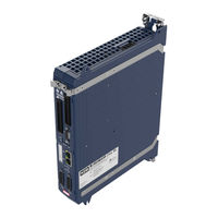
KEB COMBIVERT S6 Series Instructions For Use Manual (74 pages)
INSTALLATION S6 HOUSING 2
Brand:
KEB
| Category:
Servo Drives
| Size: 5 MB
Table of Contents
Preface
3
Signal Words and Symbols
3
More Symbols
3
Laws and Guidelines
4
Warranty and Liability
4
Support
4
Copyright
4
Table of Contents
5
List of Figures
8
List of Tables
9
Glossary
10
Standards for Drive Converters / Control Cabinets
12
Product Standards that Apply Directly to the Drive Converter
12
Basic Standards to Which Drive Converter Standards Refer Directly
12
Standards that Are Used in the Environment of the Drive Converter
13
Basic Safety Instructions
14
Target Group
14
Transport, Storage and Proper Use
14
Installation
15
Electrical Connection
16
EMC-Compatible Installation
17
Voltage Test
17
Insulation Measurement
17
Start-Up and Operation
18
Maintenance
19
Repair
20
Disposal
20
Product Description
21
Specified Application
21
Residual Risks
21
Unintended Use
21
Product Features
22
Part Code
23
Table 1: Part Code
23
Technical Data
24
Operating Conditions
24
Climatic Environmental Conditions
24
Table 2: Climatic Environmental Conditions
24
Mechanical Ambient Conditions
25
Chemical / Mechanical Active Substances
25
Table 3: Mechanical Ambient Conditions
25
Table 4: Chemical / Mechanical Active Substances
25
Electrical Operating Conditions
26
Device Classification
26
Electromagnetic Compatibility
26
Table 5: Device Classification
26
Table 6: Electromagnetic Compatibility
26
Mounting Instructions for Control Cabinet Installation
27
Dimensions and Weights
27
Built-In Version
27
Figure 1: Dimensions Built-In Version Housing 2
27
Table 7: Mounting Instructions for Control Cabinet Installation
27
Control Cabinet Installation
28
Figure 2: Mounting Distances
28
Figure 3: Control Cabinet Ventilation
28
Unit Data 400 V Devices
29
Overview
29
Rated Operation
29
Table 8: Overview Unit Data 400 V Devices
29
Voltage and Frequency Data
30
Example for the Calculation of the Motor Voltage
30
Table 9: Input Voltages and Frequencies 400V Units
30
Table 10: Input Voltages for DC Operation 400V Units
30
Table 11: Output Voltages and Frequencies 400V Units
30
Table 12: DC Switching Level 400V Units
30
Table 13: Example for the Calculation of the Motor Voltage
30
Input and Output Currents / Overload
31
Table 14: Input Currents 400V Units
31
Table 15: Output Currents 400 V Units
31
Unit Data 230 V Devices
32
Overview
32
Rated Operation
32
Table 16: Overview Unit Data 230 V Devices
32
Voltage and Frequency Data
33
Table 17: Input Voltages and Frequencies 230V Units
33
Table 18: Input Voltages for DC Operation 230V Units
33
Table 19: Output Voltages and Frequencies 230V Units
33
Table 20: DC Switching Level 230V Units
33
Input and Output Currents / Overload
34
Table 21: Input Currents 230V Units
34
Table 22: Output Currents 230V Class
34
General Data
35
Overload Characteristic (OL)
35
Turn-Off Time Depending on the Overload at 400 V Units
36
Figure 4: Switch-Off Time T Depending on the Overload I / in (OL) 400 V Units
36
Turn-Off Time Depending on the Overload at 230 V Units
37
Figure 5: Switch-Off Time T Depending on the Overload I / in (OL) 230 V Units
37
Maximum Current (OL2)
38
Figure 6: Overload Characteristic in the Lower Speed Range (OL2)
38
Table 23: Frequency-Dependent Maximum Current for Unit Size 07 400 V Units
39
Table 24: Frequency-Dependent Maximum Current for Unit Size 09 400 V Units
39
Table 25: Frequency-Dependent Maximum Current for Unit Size 10 400 V Units
39
Table 26: Frequency-Dependent Maximum Current for Unit Size 07 230 V Units
40
Table 27: Frequency-Dependent Maximum Current for Unit Size 09 230 V Units
40
Switching Frequency and Temperature
41
Table 28: Switching Frequency and Temperature
41
Protection of the Drive Converter
42
Table 29: Fusing of the Drive Converters 400 V Units, 3-Phase
42
Table 30: Fusing of the Drive Converters 230 V Units, 1-Phase
42
DC Link / Braking Transistor Function
43
DC Link / Braking Transistor Function of the 400 V Units
43
DC Link / Braking Transistor Function of the 230 V Units
43
Table 31: DC Link / Braking Transistor Function of the 400 V Units
43
Table 32: DC Link / Braking Transistor Function of the 230 V Units
43
Power Dissipation 400 V Units
44
Power Dissipation 230 V Units
44
Figure 7: Block Diagram of the Energy Flow
44
Table 33: Power Dissipation 400 V Units
44
Table 34: Power Dissipation 230 V Units
44
Fan
45
Switching Behaviour of the Fan
45
Switching Points of the Fan
45
Figure 8: Switching Behaviour of the Fan
45
Installation and Connection
46
Overview of the Combivert S6
46
Figure 9: Overview COMBIVERT S6
46
Connection of the Power Unit
48
Connection of the Voltage Supply
48
Figure 10: Input Circuit / Drive Converter Type 400 V Units
48
Figure 11: Input Circuit / Drive Converter Type 230 V Units
48
Line Terminal Strip X1A
49
Figure 12: Line Terminal Strip X1A
49
Protective Earth and Function Earth
50
Protective Earth
50
Functional Earthing
50
Advertisement
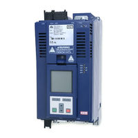
KEB COMBIVERT S6 Series Instructions For Use Manual (66 pages)
Brand:
KEB
| Category:
Media Converter
| Size: 5 MB
Table of Contents
Preface
3
Signal Words and Symbols
3
More Symbols
3
Laws and Guidelines
4
Warranty and Liability
4
Support
4
Copyright
4
Table of Contents
5
List of Figures
8
List of Tables
9
Glossary
10
Standards for Drive Converters / Control Cabinets
12
Product Standards that Apply Directly to the Drive Converter
12
Basic Standards to Which Drive Converter Standards Refer Directly
12
Standards that Are Used in the Environment of the Drive Converter
13
1 Basic Safety Instructions
14
Target Group
14
Transport, Storage and Proper Use
14
Installation
15
Electrical Connection
16
EMC-Compatible Installation
17
Voltage Test
17
Insulation Measurement
17
Start-Up and Operation
18
Maintenance
19
Repair
20
Disposal
20
2 Product Description
21
Specified Application
21
Residual Risks
21
Unintended Use
21
Product Features
22
Part Code
23
Table 1: Part Code
23
3 Technical Data
24
Operating Conditions
24
Climatic Environmental Conditions
24
Table 2: Climatic Environmental Conditions
24
Mechanical Ambient Conditions
25
Chemical / Mechanical Active Substances
25
Table 3: Mechanical Ambient Conditions
25
Table 4: Chemical / Mechanical Active Substances
25
Electrical Operating Conditions
26
Device Classification
26
Electromagnetic Compatibility
26
Table 5: Device Classification
26
Table 6: Electromagnetic Compatibility
26
Mounting Instructions for Control Cabinet Installation
27
Dimensions and Weights
27
Built-In Version
27
Figure 1: Dimensions Built-In Version Housing 4
27
Table 7: Mounting Instructions for Control Cabinet Installation
27
Control Cabinet Installation
28
Figure 2: Mounting Distances
28
Figure 3: Control Cabinet Ventilation
28
Unit Data
29
Overview
29
Rated Operation
29
Table 8: Overview Unit Data
29
Voltage and Frequency Data
30
Example for the Calculation of the Motor Voltage
30
Table 9: Input Voltage and Frequencies
30
Table 10: Input Voltage for DC Operation
30
Table 11: Output Voltage and Frequencies
30
Table 12: DC Switching Level
30
Input and Output Currents / Overload
31
Overload Characteristic (OL)
31
Table 13: Input Currents
31
Table 14: Output Currents
31
Turn-Off Time Depending on the Overload at Unit Size 12 and 13
32
Figure 4: Turn-Off Time Depending on the Overload (OL) at Unit Size 12 and 13
32
Turn-Off Time Depending on the Overload at Unit Size 14
33
Figure 5: Turn-Off Time Depending on the Overload (OL) at Unit Size 14
33
Maximum Current (OL2)
34
Figure 6: Overload Characteristic in the Lower Speed Range (OL2)
34
Table 15: Frequency-Dependent Maximum Current for Unit Size 12
35
Table 16: Frequency-Dependent Maximum Current for Unit Size 13
35
Table 17: Frequency-Dependent Maximum Current for Unit Size 14
35
Switching Frequency and Temperature
36
Protection of the Drive Converter
36
Table 18: Switching Frequency and Temperature
36
Table 19: Protection of the Drive Converter
36
DC Link / Braking Transistor Function
37
Figure 7: Block Diagram of the Energy Flow
37
Table 20: DC Link / Braking Transistor Function of the 400 V Units
37
Power Dissipation
38
Table 21: Power Dissipation
38
Fan
39
Switching Behaviour of the Fan
39
Switching Points of the Fan
39
Figure 8: Switching Behaviour of the Fan
39
Table 22: Fan
39
KEB COMBIVERT S6 Series Instructions For Use Manual (52 pages)
Installation Control COMPACT
Brand:
KEB
| Category:
Servo Drives
| Size: 4 MB
Table of Contents
Table of Contents
3
Introduction | 1
7
Markings
7
Warnings
7
Information Notes
7
Symbols and Markers
8
Laws and Guidelines
8
Warranty and Liability
8
Support
8
Copyright
8
General Safety Instructions
10
Product Description | 3
11
Description of the Control Board COMPACT
11
Variants of the Control Board Pro
11
Safety Functions
11
Accessories
12
Tab. 1 Connector Sets
12
Connection and Control Elements
13
Motor Monitoring X1C (Temperature, Brake)
13
Tab. 2 Overview Connection and Control Elements
13
Control Terminal Strip X2A
14
Safety Terminal Block X2B
14
CAN Bus and Analog Inputs and Outputs X2C
14
Encoder Interfaces X3A, X3B
14
Diagnostic Interface X4A
14
Fieldbus Interfaces X4B, X4C
14
Status Leds
14
Boot Display
14
VCC - Led
15
Net St - Led
15
Dev St - Led
15
Opt - Led
15
Tab. 3 Leds at Power on
15
Tab. 4 Function VCC LED
15
Tab. 5 Function NET ST - LED
15
Tab. 6 Function DEV ST - LED
15
Tab. 7 Function OPT - LED
15
Connection of the Control
16
Assembly of Wires
16
Tab. 8 Wire-End Ferrules and Stripping Length
16
Terminal Strip X2A
17
Digital Inputs
17
Tab. 9 Assignment of the Terminal Strip X2A
17
Digital Outputs
18
Relay Output
18
Voltage Supply
19
Terminal Block X2B
19
Inputs STO
19
Tab. 10 Assignment of the Terminal Strip X2B
19
Digital Outputs
20
Voltage Input
20
Tab. 11 OSSD Pulse Width Depending on the Input Voltage
20
Terminal Block X2C
21
Tab. 12 Calculation the Current Consumption
21
Tab. 13 Assignment of the Terminal Block X2C
21
Analog Input
22
Analog Output
22
Diagnosis/Visualisation X4A
24
Assignment of the Terminal Strip X4A
24
Data Cable RS232 PC-Drive Controller
24
Abb. 1 Pin Assignment Socket D-Sub-9 (Top View)
24
Abb. 2 Serial Cable for the Connection to a PC
24
Tab. 14 Serial Interfaces
24
Tab. 15 Connecting Cable
24
USB-Serial Converter
25
Connection of the RS485 Interface
25
Fieldbus Interfaces
26
Type Code Fieldbus
26
Can
26
Abb. 3 Connection CAN Bus
26
Tab. 16 Assignment of the Terminal Block X2C
26
Ethercat
27
Abb. 4 RJ45 Socket Front View
28
Tab. 17 PIN Assignment RJ45 Ethercat
28
Tab. 18 Function of the Leds
28
Varan
29
Abb. 5 RJ45 Socket Front View
29
Tab. 19 Error Status List
29
Tab. 20 PIN Assignment RJ45 VARAN
29
KEB COMBIVERT S6 Series Instructions For Use Manual (48 pages)
Brand:
KEB
| Category:
Media Converter
| Size: 2 MB
Table of Contents
Table of Contents
3
Introduction | 1
7
Markings
7
Warnings
7
Information Notes
7
Symbols and Markers
8
Laws and Guidelines
8
Warranty and Liability
8
Support
8
Copyright
9
Validity of this Manual
9
Target Group
9
General Safety Instructions
10
Installation
10
Start-Up and Operation
11
Maintenance
11
Product Description
12
Description of the Control Board PRO
12
Variants of the Control Board
12
Accessories
12
Tab. 1 Connector Sets
13
Connection and Control Elements
14
Motor Monitoring X1C (Temperature, Brake)
14
Tab. 2 Overview Connection and Operating Elements
14
Control Terminal Strip X2A
15
Safety Terminal Block X2B
15
Encoder Interfaces X3A, X3B
15
Diagnostic Interface X4A
15
Fieldbus Interface X4B
15
Fieldbus Interface X4C
15
Rotary Coding Switch
15
Status Leds
15
Boot Display
15
VCC - Led
16
Net St - Led
16
Dev St - Led
16
Opt - Led
16
Tab. 3 Leds at Power on
16
Tab. 4 Function VCC LED
16
Tab. 5 Function NET ST - LED
16
Tab. 6 Function DEV ST - LED
16
Tab. 7 Function OPT - LED
16
Connection of the Control
18
Assembly of Wires
18
Tab. 8 Wire End Ferrules and Stripping Length
18
Terminal Strip X2A
19
Tab. 9 Assignment of the Terminal Strip X2A
19
Digital Inputs
20
Digital Outputs
20
Relay Output
21
Analog Input
22
Analog Output
23
Voltage Supply
24
Tab. 10 Calculation the Current Consumption
24
Safety Module X2B
26
Safety Manual Type
26
Diagnosis/Visualisation X4A | 6
27
Assignment of the Terminal Strip X4A
27
Fig. 1 Pin Assignment Socket D-Sub-9 (Top View)
27
Tab. 11 Serial Interfaces
27
Tab. 12 Accessories
27
Tab. 13 Connecting Cable
27
Data Cable RS232 PC-Drive Controller
28
USB-Serial Converter
28
Connection of the RS485 Interface
28
Remote Control
28
Fig. 2 Serial Cable for the Connection to a PC
28
Tab. 14 Wiring of the DE-9 - RJ45 Adapters
28
Fieldbus Interfaces | 7
29
KEB COMBIVERT S6 Series Instructions For Use Manual (40 pages)
Functional safety
Brand:
KEB
| Category:
Controller
| Size: 1 MB
Table of Contents
Preface
3
Signal Words and Symbols
3
More Symbols
3
Laws and Guidelines
4
Warranty and Liability
4
Support
4
Copyright
4
Table of Contents
5
List of Figures
7
List of Tables
8
Glossary
9
Standards for Drive Converters / Control Cabinets
11
Product Standards that Apply Directly to the Drive Converter
11
Basic Standards to Which Drive Converter Standards Refer Directly
11
Standards that Are Used in the Environment of the Drive Converter
12
1 Basic Safety Instructions
13
Target Group
13
Validity of this Manual
13
Electrical Connection
14
Start-Up and Operation
14
2 Product Description
15
Device Identification
15
Table 1: Numerical Code
15
3 Safety Functions
16
General Instructions
16
Safe Torque off (Safe Torque off - STO)
17
Emergency Stop According en 60204
18
Calculation of the Rotation Angle Triggered by the Jerk
18
Table 2: Calculation of the Jerk
18
Classification Of Sto According Iec 61508
19
Classification Of Sto According En Iso 13849
19
Safe Brake Control (Safe Brake Control - SBC)
19
Requirements for the Brake
19
Table 3: Classifications of STO
19
Table 4: Requirements for the Brake
19
Classification Of Sbc According Iec 61508
20
Classification Of Sbc According En Iso 13849
20
Table 5: Classifications of SBC
20
4 Description of the Terminals
21
Figure 1: Description of the Terminals
21
Table 6: Mechanical Specification of Terminal Strip X2B
21
Inputs
22
Specification Of The Sto Inputs
22
STO with OSSD Signals
22
Specification Of The Sbc Inputs
22
SBC with OSSD Signals
22
Table 7: Specification of the STO Inputs
22
Table 8: STO with OSSD Signals
22
Table 9: Specification of the SBC Inputs
22
Outputs
23
Output STO
23
Output SBC
23
Brake Output
23
Status Leds
23
Status-LED Safety Module
23
Table 10: Status-LED Safety Module
23
5 Installation
24
Additional Instructions
24
KEB COMBIVERT S6 Series Installation Manual (33 pages)
Control Circuit
Brand:
KEB
| Category:
Circuit breakers
| Size: 1 MB
Table of Contents
Table of Contents
3
1 Preface
6
General
6
Safety Instructions
6
Validity and Liability
6
Copyright
6
Specified Application
6
Product Description
7
2 Control
9
Features of the Control
9
Overview
9
Control Terminal Strip X2A
10
Safety Terminal Block X2B
10
CAN Terminal Block X2C
10
Analog Inputs X2D
10
Diagnostic Interface X4A
10
Encoder Interfaces X3A, X3B
10
Connection of the Control
11
Assembly of the Wires
11
Assignment of the Terminal Strip X2A
12
Connection of the Digital Inputs
13
Connection of the Digital Outputs
13
Assignment of the STO Terminal Strip X2B
14
Inputs
14
Specification Of The Sto Inputs
14
Sto With Ossd Signals
14
Output Sto
14
Assignment of the CAN Terminal Strip X2C
15
Assignment of the Terminal Strip for Analog Inputs X2D
15
Connection of the Analog Inputs
15
Diagnosis/Visualisation
16
Assignment of the Interface X4A
16
Connection of the RS232 Interface
16
Connection of the RS485 Interface
16
Wiring RS485 Full Duplex
17
Wiring RS485 Half Duplex
17
Socket X4C Ethercat in and X4B Ethercat out
18
Encoder Parameter
18
Encoder Interfaces X3A and X3B
19
3 Safety Function STO
20
Emergency Stop According en 60204
21
Classification of STO According IEC 61508
22
Classification of STO According en ISO 13849
22
Additional Instructions
22
Functional Description
23
Wiring Examples
24
Direct Switching off with Emergency Stop Switch
24
Direct Switching off with Emergency Stop Switch and Monitoring of the Wiring
25
Direct Switching off by Safety Module with Test Pulses
26
Wiring SS1
27
4 Certification
29
Annex to the Declaration of Conformity
29
5 Revision History
31
KEB COMBIVERT S6 Series Installation Instructions (2 pages)
Brand:
KEB
| Category:
Servo Drives
| Size: 0 MB
Table of Contents
Required Tools
1
General Overview
1
Loosening Screws
1
Removing Screws and Clamping Brackets
2
Placing Shield Clamp on Top
2
Reattaching the Screws and Clamping Brackets
2
Advertisement
Related Products
KEB COMBIVERT S4
KEB COMBIVERT Series
KEB COMBIVERT F5 Series
KEB COMBIVERT F6 series
KEB COMBIVERT G6 series
KEB COMBIVERT H6 Series
KEB COMBIVERT F4-S Series
KEB COMBIVERT F5-B Series
KEB COMBIVERT F5-G Series
KEB COMBIVERT F5-S Series
KEB Categories
DC Drives
Controller
Inverter
Control Unit
Industrial Equipment
More KEB Manuals
Login
Sign In
OR
Sign in with Facebook
Sign in with Google
Upload manual
Upload from disk
Upload from URL