KEB COMBIVERT S6 Instructions For Use Manual
Hide thumbs
Also See for COMBIVERT S6:
- Instructions for use manual (82 pages) ,
- Installation manual (33 pages) ,
- Installation instructions (2 pages)

Related Manuals for KEB COMBIVERT S6


Summary of Contents for KEB COMBIVERT S6
- Page 1 COMBIVERT S6 INSTRUCTIONS FOR USE | INSTALLATION S6 HOUSING 4 Translation of the original manual Document 20106280 EN 03...
-
Page 3: Preface
PrefAce Preface The described hard- and software are developments of the KEB Automation KG. The enclosed documents correspond to conditions valid at printing. Misprint, mistakes and technical changes reserved. Signal words and symbols Certain operations can cause hazards during the installation, operation or thereafter. -
Page 4: Laws And Guidelines
If applicable, the license terms of this software are contained in the instructions for use. The instructions for use are already available to you, can be downloaded free of charge from the KEB website or can be requested from the respec- tive KEB contact person. -
Page 5: Table Of Contents
TAbLe Of cONTeNTS Table of contents Preface ..............................3 Signal words and symbols ......................3 More symbols ..........................3 Laws and guidelines ........................4 Warranty and liability ........................4 Support ............................4 Copyright ............................4 Table of contents ........................... 5 List of figures ............................8 List of Tables ............................ - Page 6 3.3.9.1 Switching behaviour of the fan ..................39 3.3.9.2 Switching points of the fan ....................39 4 Installation and connection ........40 4.1 Overview of the cOMbIVerT S6 ....................40 4.2 connection of the power unit ....................... 42 4.2.1 Connection of the voltage supply ..................42 4.2.1.1 Line terminal strip X1A ....................
- Page 7 TAbLe Of cONTeNTS 4.2.5.4 Motor cable length for parallel operation of motors ............47 4.2.5.5 Motor cable cross-section ....................47 4.2.5.6 Interconnection of the motor .................... 47 4.2.5.7 Terminal strip X1B motor connection ................47 4.2.5.8 Wiring of the motor ......................48 4.2.6 Connection of a braking resistor ..................
-
Page 8: List Of Figures
LIST Of fIGUreS List of figures Figure 1: Dimensions built-in version housing 4 ................27 Figure 2: Mounting distances ......................28 Figure 3: Control cabinet ventilation....................28 Figure 4: Turn-off time depending on the overload (OL) at unit size 12 and 13 ......32 Figure 5: Turn-off time depending on the overload (OL) at unit size 14 .......... -
Page 9: List Of Tables
LIST Of TAbLeS List of Tables Table 1: Part code..........................23 Table 2: Climatic environmental conditions ................... 24 Table 3: Mechanical ambient conditions ..................25 Table 4: Chemical / mechanical active substances ............... 25 Table 5: Device classification......................26 Table 6: Electromagnetic compatibility ..................26 Table 7: Mounting instructions for control cabinet installation ............ -
Page 10: Glossary
Business-to-business IP xx Degree of protection (xx for level) BiSS Open source real-time interface for KEB product The KEB product is subject of this sensors and actuators (DIN 5008) manual Fieldbus system Silicium temperature sensor (pola- Complete drive module including... - Page 11 GLOSSAry Programmable logic controller PT100 Temperature sensor with R0=100Ω PT1000 Temperature sensor with R0=1000Ω PTC-resistor for temperature detec- tion Pulse width modulation RJ45 Modular connector with 8 lines Synchronous sensorless closed loop SELV Safety Extra Low Voltage (< 60 V) The security integrity level is a measure for quantifying the risk reduction.
-
Page 12: Standards For Drive Converters / Control Cabinets
STANDArDS fOr DrIVe cONVerTerS / cONTrOL cAbINeTS Standards for drive converters / control cabinets Product standards that apply directly to the drive converter EN 61800-2 Adjustable speed electrical power drive systems - Part 2: General requirements - Rating specifications for low voltage adjustable frequency a.c. power drive systems (VDE 0160-102, IEC 61800-2) EN 61800-3 Speed-adjustable electrical drives. Part 3: EMC requirements and specific test methods (VDE 0160-103, IEC 61800-3) -
Page 13: Standards That Are Used In The Environment Of The Drive Converter
STANDArDS fOr DrIVe cONVerTerS / cONTrOL cAbINeTS EN 61000-4-5 Electromagnetic compatibility (EMC) - Part 4-5: Testing and measurement techniques - Surge immunity test (IEC 61000-4-5); German version EN 61000-4-5 EN 61000-4-6 Electromagnetic compatibility (EMC) - Part 4-6: Testing and measurement techniques - Immunity to conducted disturbances, induced by radio-frequency fields (IEC 61000-4-6); German version EN 61000-4-6 EN 61000-4-34... -
Page 14: Basic Safety Instructions
► Read the instructions for use ! ► Observe the safety and warning instructions ! ► If anything is unclear, please contact KEB Automation KG ! 1.1 Target group This instruction manual is determined exclusively for electrical personnel. Electrical per- sonnel for the purpose of this instruction manual must have the following qualifications: •... -
Page 15: Installation
bASIc SAfeTy INSTrUcTIONS Drive converters contain electrostatic sensitive components. ► Avoid contact. ► Wear ESD-protective clothing. Do not store drive converters • in the environment of aggressive and/or conductive liquids or gases. • with direct sunlight. • outside the specified environmental conditions. 1.3 Installation DANGer Do not operate in an explosive environment! -
Page 16: Electrical Connection
If personnel protection is required during installation of the system, suitable protective devices must be used for drive converters. www.keb.de/fileadmin/media/Manuals/knowledge/04_techinfo/00_gene- ral/ti_rcd_0400_0002_gbr.pdf Installations which include drive converter shall be equipped with additional control and protective devices in accordance with the relevant applicable safety requirements, e.g. -
Page 17: Emc-Compatible Installation
According to EN 60204-1 it is permissible to disconnect already tested com- ponents. Drive converters of the KEB Automation KG are delivered ex works voltage tested to 100% according to product standard. 1.4.3 Insulation measurement An insulation measurement (in accordance with EN 60204-1 chapter 18.3) with DC... -
Page 18: Start-Up And Operation
If a drive converter with electrolytic capacitors in a DC link (see technical data) has not been in operation for more than one year, observe the following instructions. www.keb.de/fileadmin/media/Manuals/knowledge/04_techinfo/00_gene- ral/ti_format_capacitors_0400_0001_gbr.pdf continuous operation (S1) with load > 60 % or from a rated motor... -
Page 19: Maintenance
For applications that require cyclic switching off and on of the drive converter, maintain an off-time of at least 5 min after the last switch on. If you require shorter cycle times please contact KEB Automation KG. Short-circuit resistance The drive converters are conditional short-circuit proof. After resetting the internal pro- tection devices, the function as directed is guaranteed. -
Page 20: Repair
1.7 Disposal Electronic devices of the KEB Automation KG are exclusively professional devices for further industrial processing (so-called B2B devices). Manufacturers of B2B devices are obliged to take back and recycle devices manufac- tured after 14.08.2018. -
Page 21: Product Description
PrODUcT DeScrIPTION 2 Product Description The drive converter series COMBIVERT S6 is optimized for the operation at synchro- nous and asynchronous motors. The integrated safety function STO has been devel- oped for the use in safety-oriented applications. The COMBIVERT meets the requirements of the Low-Voltage Directive. The harmo-... -
Page 22: Product Features
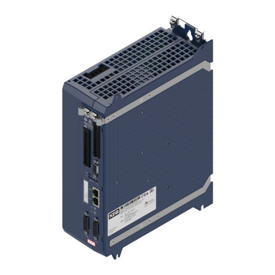
COMBIVERT S6 Power range: 4...7.5 kW / 400 V Housing: The COMBIVERT S6 is characterized by the following features: • For asynchronous, synchronous, IPM or synchronous reluctance motors • With encoder or encoderless SCL and ASCL for accurate speed control •... -
Page 23: Part Code
3: Type 3 for Strg A (STO / SBC / SLS etc.) 5: Type 5 STO / SLS / etc. FSOE A: APPLICATION Control type K: COMPACT P: PRO Series COMBIVERT S6 Unit size 07…14 Table 1: Part code The type code is not used as order code, but only for identification ! EtherCAT is a registered trademark and patented technology licensed ®... -
Page 24: Technical Data
OPerATING cONDITIONS 3 Technical Data Unless otherwise indicated, all electrical data in the following chapter refer to a 3-phase AC voltage supply. 3.1 Operating conditions 3.1.1 climatic environmental conditions Storage Standard class Descriptions Surrounding temperature EN 60721-3-1 -25…55 °C Relative humidity EN 60721-3-1 5…95 % (without condensation) Storage height... -
Page 25: Mechanical Ambient Conditions
OPerATING cONDITIONS 3.1.2 Mechanical ambient conditions Storage Standard class Descriptions Vibration amplitude 1.5 mm (2…9 Hz) Vibration limits EN 60721-3-1 Acceleration amplitude 5 m/s² (9…200 Hz) Shock limit values EN 60721-3-1 40 m/s²; 22 ms Transport Standard class Descriptions Vibration amplitude 3.5 mm (2…9 Hz) Vibration limits EN 60721-3-2 Acceleration amplitude 10 m/s²... -
Page 26: Electrical Operating Conditions
OPerATING cONDITIONS 3.1.4 electrical operating conditions 3.1.4.1 Device classification requirement Standard class Descriptions – EN 61800-5-1 Overvoltage category EN 60664-1 – Non-conductive pollution, occasional conden- Pollution degree EN 60664-1 sation when PDS is out of service Table 5: Device classification 3.1.4.2 Electromagnetic compatibility An external filter is required for devices without an internal filter in order to comply with the following limits. -
Page 27: Mounting Instructions For Control Cabinet Installation
DIMeNSIONS AND WeIGHTS 3.1.4.3 Mounting instructions for control cabinet installation The following mounting materials with the appropriate quality must be used for mounting the drive converters. required material Tightening torque 3.2 Nm Screw assembly ISO 7045 - M6 - 8.8 29 lb inch Table 7: Mounting instructions for control cabinet installation... -
Page 28: Control Cabinet Installation
DIMeNSIONS AND WeIGHTS 3.2.2 control cabinet installation Power dissipation for the control cabinet dimension => „Power dissipation“. A lower value can be used here depending on the operating mode/load. Installation of the drive converter For reliable operation, the drive converter must be installed without clearance on a smooth, closed, bare metal mounting plate. -
Page 29: Unit Data
UNIT DATA 3.3 Unit data 3.3.1 Overview The technical data are for 2/4-pole standard motors. With other pole numbers the drive converter must be dimensioned onto the motor rated current. Contact KEB for special or medium frequency motors. Unit size Housing... -
Page 30: Voltage And Frequency Data
UNIT DATA 3.3.3 Voltage and frequency data Input voltage and frequencies Rated input voltage Rated input voltage UL N_UL Input voltage range 184…550 Mains phases Mains frequency / Hz 50 / 60 Mains frequency tolerance ±f / Hz ±2 Table 9: Input voltage and frequencies Input voltage for Dc operation Rated input voltage DC... -
Page 31: Input And Output Currents / Overload
The values refer in % to the rated output current I 3.3.4.1 Overload characteristic (OL) All COMBIVERT S6 can be operated time-limited at rated switching frequency even in overload.Further information can be found in the diagrams “Turn-off time depending on the overload at unit size 12 and 13”... -
Page 32: Turn-Off Time Depending On The Overload At Unit Size 12 And 13
UNIT DATA 3.3.4.2 Turn-off time depending on the overload at unit size 12 and 13 Overload characteristic (Oc Level 300%) ① Motor current / drive converter rated currrent in % Detail view in the range from 200 % to 300 % ②... -
Page 33: Turn-Off Time Depending On The Overload At Unit Size 14
UNIT DATA 3.3.4.3 Turn-off time depending on the overload at unit size 14 Overload characteristic (OC Level 216%) ① Motor current / drive converter rated currrent in % Detail view in the range from 155 % to 210 % ② Motor current / drive converter rated currrent in % Legend 1 Thermal overload limit... -
Page 34: Maximum Current (Ol2)
UNIT DATA 3.3.4.4 Maximum current (OL2) It can be adjusted in the drive converter parameters if error (OL2) shall be triggered when exceeding the maximum currents, or if the switching frequency is automatically reduced (derating). The following tables indicate the permissible maximum current for 6 output frequency values. -
Page 35: Table 15: Frequency-Dependent Maximum Current For Unit Size 12
UNIT DATA frequency-dependent maximum current Unit size rated switching frequency 8 kHz Output frequency / Hz 12.5 4 kHz frequency-dependent maximum current @ f 8 kHz Basic Time Period = 62.5 µs (Parameter is22=0) 16 kHz 7 kHz frequency-dependent maximum current @ f Basic Time Period = 71.4 µs (Parameter is22=1) 14 kHz frequency-dependent maximum current @ f... -
Page 36: Switching Frequency And Temperature
UNIT DATA 3.3.5 Switching frequency and temperature Unit size Rated switching frequency / kHz Max. switching frequency / kHz S_max Max. heat sink temperature / °C Temperature for derating the switching frequency / °C temperature for uprating the switching frequency / °C Temperature for switching to rated switching frequency / °C Table 18: Switching frequency and temperature... -
Page 37: Dc Link / Braking Transistor Function
Activation of the braking transistor function The function must be activated with parameter "is30 braking transistor func- tion" in order to use the braking transistor (GTR7). Further information can be found in the download area of www.keb.de under the search term „S6 Programming... -
Page 38: Power Dissipation
UNIT DATA NOTICE Destruction of the drive converter ► If the error „ERROR GTR7 always ON“ occurs, the drive converter must be disconnected from the mains supply within 5 minutes! 3.3.8 Power dissipation Unit size Power dissipation at nominal operating Power dissipation at DC supply D_dc Table 21:... -
Page 39: Fan
UNIT DATA 3.3.9 fan Unit size Number Heat sink fan Speed-variable — Table 22: NOTICE Destruction of the fan! ► Take care that no foreign substances drop into the fan! 3.3.9.1 Switching behaviour of the fan The fan has different switch-on and switch-off points. The switching point for the switch- on temperature ①... -
Page 40: Installation And Connection
OVerVIeW Of THe cOMbIVerT S6 4 Installation and connection 4.1 Overview of the cOMbIVerT S6 representation by the example of an APPLIcATION control board Mains input Motor output / Connection for braking resistor Temperature monitoring; brake control Strain relief Control terminal strip... - Page 41 OVerVIeW Of THe cOMbIVerT S6 Instructions for use COMBIVERT S6 control board APPLICATION www.keb.de/fileadmin/media/Manuals/dr/ma_dr_s6-cu-a-inst-20109645_en.pdf Instructions for use COMBIVERT S6 control board COMPACT www.keb.de/fileadmin/media/Manuals/dr/ma_dr_s6-cu-k-inst-20087885_en.pdf Instructions for use COMBIVERT S6 control board www.keb.de/fileadmin/media/Manuals/dr/ma_dr_s6-cu-p-inst-20156056_en.pdf...
-
Page 42: Connection Of The Power Unit
Of THe POWer UNIT 4.2 connection of the power unit 4.2.1 connection of the voltage supply The COMBIVERT S6 corresponds to the drive converter type A1. This type can be supplied both by mains and via DC terminals. The start- ing current limiting is arranged before the DC link. -
Page 43: Protective Earth And Function Earth
The use of the functional earth (FE) is not required if the frequency inverter is EMC-technically wired as described in the manual => Before starting. The functional earth may not be wired green / yellow! Notes on EMC-compatible installation can be found here. www.keb.de/fileadmin/media/Manuals/emv/0000neb0000.pdf... -
Page 44: Ac Connection
⑤ HF filter out internal filter ⑥ KEB COMBIVERT Figure 13: Connection of the mains supply The service life of drive converters with voltage DC link depends on the DC voltage, sur- rounding temperature and the current load of the electrolytic capacitors in the DC link. The use of mains chokes can increase the service life of the capacitors to a considerable extent, especially when connecting to „hard“... -
Page 45: Supply Line
DC voltage 260…750 V Type aR ② Fuses Pay attention to the permissible voltage range ! ③ KEB COMBIVERT Figure 14: Connection at DC voltage supply 4.2.4.2 Terminal strip X1B DC connection Name function R -- ++ U V W... -
Page 46: Connection Of The Motor
100 m < 5 mA Table 23: Maximum motor cable length at AC supply The line length can be extend significant by using motor chokes or filters. KEB recommends the use of motor chokes or filters for a line length upto 50 m. Motor chokes or filters are absolutely necessary upto 100 m. 4.2.5.3 Motor line length at operation with DC voltage The maximum motor cable length at DC operation is basically dependent on the capaci- ty of the motor cable. The internal filter is not active at DC operation. External measures... -
Page 47: Motor Cable Length For Parallel Operation Of Motors
cONNecTION Of THe POWer UNIT 4.2.5.4 Motor cable length for parallel operation of motors The resulting motor cable length for parallel operation of motors, or parallel installation with multiple cables arises from the following formula: resulting motor cable length = ∑single line length x √Number of motor lines 4.2.5.5 Motor cable cross-section The motor cable cross-section is dependent •... -
Page 48: Wiring Of The Motor
4.2.5.8 Wiring of the motor Legend ➀ ➁ ➂ ④ Control ① KEB COMBIVERT P A/K Apply motor cable, shielding on both sides over a ② large surface on the function earth (screening shield or mounting plate) ③ Three-phase motor Temperature monitoring (optional) ④... -
Page 49: Wiring Of An Intrinsically Safe Braking Resistor
Only "intrinsically safe" braking resistors are permissible for this oper- ation, since these resistors interrupt themselves at fault such as safety fuse without fire risk. The delivered intrinsically safe braking resistors by KEB are described in the following link. Technical data and design for intrinsically safe braking re- sistors. -
Page 50: Brake Control And Temperature Detection
brAKe cONTrOL AND TeMPerATUre DeTecTION 4.3 brake control and temperature detection Name Notes Brake control / output + Brake control / output - Reserved Reserved Temperature detection / input+ Temperature detection / input- Figure 20: Assignment of the terminal block X1C 4.3.1 Specification and connection of the brake control Name BR+ (X1C.1);... -
Page 51: Specification And Connection Of The Temperature Detection
► Cables of the motor temperature sensor inside the motor cable only permissible with double shielding ! A switchable KTY84/PTC evaluation is implemented in the KEB COMBIVERT. The de- sired operating mode can be adjusted by software (dr33). Operating mode... -
Page 52: Connection Of A Kty Sensor
brAKe cONTrOL AND TeMPerATUre DeTecTION • Deactivate the evaluation (pn33 =7) • Install bridge between terminal X1C.5 and X1C.6 (dr33=1) 4.3.4 connection of a KTy sensor NOTICE No protection of the motor winding in case of wrong connection. ► Operate KTY sensors in forward direction. Non-observance leads incorrect measurement in the upper temperature range. -
Page 53: Connection Of Ptc, Temperature Switch Or Pt1000
brAKe cONTrOL AND TeMPerATUre DeTecTION 4.3.5 connection of PTc, temperature switch or PT1000 Name TA1 (X1C.5); TA2 (X1C.6) function Temperature sensor input dr33=1; PTC or temperature switch Stetting dr33=4; PT1000 Table 28: Connection of PTC, temperature switch or PT1000 Thermal contact (NC contact) ①... -
Page 54: Brake Control And Temperature Detection
brAKe cONTrOL AND TeMPerATUre DeTecTION 4.4 brake control and temperature detection Name Notes Brake control / output Brake control / output for supply of the feedback inputs P24Vin - 0.5 V / max. 1 A 24Vout (BR+ and 24Vout in addition 2 A) DIBR1 feedback input for brake control... -
Page 55: Specification And Connection Of The Temperature Detection
brAKe cONTrOL AND TeMPerATUre DeTecTION 4.4.2 Specification and connection of the temperature detection DANGer Use only sensors with safe isolation ! Danger to life due to electric shock ! NOTICE Malfunctions due to incorrect cable or laying! Malfunctions of the control due to capacitive or inductive coupling. ►... -
Page 56: Connection Of A Kty Sensor
brAKe cONTrOL AND TeMPerATUre DeTecTION 4.4.2.2 Connection of a KTY sensor NOTICE No protection of the motor winding in case of wrong connection. ► Operate KTY sensors in forward direction. Non-observance leads incorrect measurement in the upper temperature range. ► KTY sensors may not be combined with other detections. Name TA1 (X1C.9);... -
Page 57: Figure 26: Connection Examples Of Different Temperature Sensors
brAKe cONTrOL AND TeMPerATUre DeTecTION Thermal contact (NC contact) ① Temperature sensor (PTC) or PT1000 ① Mixed sensor chain ① Legend Connection via shield plate (if not available, place on the mounting plate). Figure 26: Connection examples of different temperature sensors... -
Page 58: Certification
Low-Voltage Directive and EMC directive.The harmonized standards of the series 61800-5-1and EN 61800-3 were used. Further information can be found in the download area of www.keb.de under the search term „Declaration of conformity“. 5.2 functional safety Drive converters with functional safety are marked with the FS logo on the nameplate. -
Page 59: Table 33: Applied Standards
ANNeX TO THe DecLArATION Of cONfOrMITy eN - Norm Name reference EN 61800-5-1 Electrical power drive systems with adjustable speed: Safety VDE 0160-105-1 requirements EN 61800-2 Basic determinations for AC drive converter VDE 0160-102 EN 61800-3 Electrical power drive systems with adjustable speed. EMC VDE 0160-103 requirements Especially for systems with functional safety additionally:... -
Page 60: Ul Marking
UL MArKING 5.4 UL Marking Acceptance according to UL is marked at KEB drive converters with the adjacent logo on the nameplate. To be conform according to UL for use on the North American and Canadian Market the following additionally instructions must be observed (original text of the UL-File): •... - Page 61 UL MArKING • WARNING – The opening of the branch circuit protective device may be an indica- tion that a fault current has been interrupted. To reduce the risk of fire or electrical shock, current-carrying parts and other components of the controller should be ex- amined and replaced if damaged. If burnout of the current element of an overload relay occurs, the complete overload relay must be replaced.”...
-
Page 62: Further Informations And Documentation
INfOrMATIONS AND DOcUMeNTATION 5.5 further informations and documentation You find supplementary manuals and instructions for the download under www.keb.de/de/service/downloads General instructions • EMC and safety instructions • Manuals for additional control boards, safety modules, fieldbus modules, etc. Instruction and information for construction and development • Input fuses in accordance with UL • Programming manual for control and power unit •... -
Page 63: Revision History
reVISION HISTOry 6 revision History Version Date Description 2015-11 Release version Change to new CI optics, revision of device data; Change of the overview; Adjustment 2017-07 of the backup data 2018-08 Inserting the unit size 14 2019-12 Adjustments of the type code, editorial changes... - Page 64 NOTES...
- Page 65 CEP 13569-430 Portal do Sol, São Carlos Brazil Gangnam Gu 135- 757 Seoul Republic of Korea Tel: +55 16 31161294 E-Mail: roberto.arias@keb.de Tel: +82 2 6253 6771 Fax: +82 2 6253 6770 E-Mail: vb.korea@keb.de KEB Automation GmbH czech republic KEB RUS Ltd.
- Page 66 Automation with Drive www.keb.de KEB Automation KG Suedstrasse 38 32683 Barntrup Tel. +49 5263 401-0 E-Mail: info@keb.de...
Need help?
Do you have a question about the COMBIVERT S6 and is the answer not in the manual?
Questions and answers