Sign In
Upload
Manuals
Brands
INVT Manuals
Servo Drives
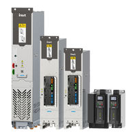
Goodrive880 Series
INVT Goodrive880 Series Manuals
Manuals and User Guides for INVT Goodrive880 Series. We have
6
INVT Goodrive880 Series manuals available for free PDF download: Hardware Manual
INVT Goodrive880 Series Hardware Manual (135 pages)
Inverter Unit
Brand:
INVT
| Category:
Servo Drives
| Size: 51 MB
Table of Contents
Table of Contents
4
Safety Precautions
7
Safety Declaration
7
Safety Definition
7
Warning Symbols
7
Safety Guidelines
7
Delivery and Installation
8
Commissioning and Running
8
Maintenance and Component Replacement
9
Disposal
9
Product Overview
10
Product Specifications
10
Product Nameplate and Model
11
Product Ratings
11
Unit Outline Dimensions and Weight
14
Derated Application
14
Derating Due to Temperature
14
Derating Due to Altitude
14
Derating Due to Carrier Frequency
15
Overload Capability
15
Hardware Principles
16
Basic Principles
16
Paralleling Principle of A8I
18
Product Structure
19
System Configuration
27
Electrical Model Selection
28
DC Fuse
28
Isolation Switch
29
Contactor
30
Mechanical Installation
31
Safety Notes
31
Installation Environment
31
Installation Procedure
32
Unpacking Inspection
32
Transportation
32
Unpacking
33
Lifting
34
Installation
36
Fastening Torque
64
Checklist
64
Electrical Installation
65
Safety Notes
65
Insulation Inspection
65
EMC Requirements
66
Power Cable
67
Control Cable
67
Wiring Suggestions
68
Shielded Cable Connection
70
Electrical Wiring
71
A1I-A4I Unit Wiring
71
A6I-A7I Unit Wiring
72
A8I Unit Wiring
73
A8N Unit Wiring
74
A8L2 Unit Wiring
75
Screw Tightening
76
A8I&A8N&A8L2 Inverter Units Isolation Switch Connection
76
Cable Specifications and Recommendations
77
Electrical Installation Checklist
78
Rectifier Control Unit (ICU)
79
ICU Composition
79
LED Indicator
80
ICU Size and Installation
81
Preparing
81
ICU Size
81
ICU Installation Space
82
ICU Installation Procedure
82
ICU Interface
84
External Standard Interfaces
85
Detailed Introduction to External Interfaces
85
ICU Function Application
88
Function Module
88
SLOT Expansion Application
89
Accessories
91
Function Expansion Module
91
BUB Buffer Module
91
A8I Installation Guide Rail and A8N, A8L2 Installation and Maintenance Bracket
91
Maintenance and Inspection
93
Periodical Inspection
93
Overview
93
Required Tools
93
Maintenance Cycle
93
Replacement of Wearing Parts
95
Capacitor
95
Cooling Fan
96
DC Fuse
99
Inverter Unit
99
Icu
104
Warranty Description
107
Appendix A Technical Data
108
Capacity
108
Grid Specifications
108
Application Standards
108
CE Marking
109
EMC Compliance Declaration
109
EMC Regulations
109
VFD Category of C2
109
VFD Category of C3
109
Appendix B Dimension Drawings
110
Appendix C Example Electrical Diagram
119
Appendix D Order No. List
122
Advertisement
INVT Goodrive880 Series Hardware Manual (95 pages)
Single-Drive VFD
Brand:
INVT
| Category:
DC Drives
| Size: 11 MB
Table of Contents
Preface
4
Table of Contents
5
Contents
7
Safety Precautions
10
Safety Declaration
10
Safety Definition
10
Warning Symbols
10
Safety Guidelines
10
Utions
10
Delivery and Installation
11
Commissioning and Running
11
Maintenance and Component Replacement
12
Disposal
12
Product Overview
13
Product Specifications
13
Product Nameplate and Model
14
Product Ratings
14
Product Dimensions and Weight
17
Derated Application
17
Derating Due to Temperature
17
Derating Due to Altitude
17
Derating Due to Carrier Frequency
18
Overload Capability
19
Hardware Principles
19
Basic Principles
19
Paralleling Principle of 11A8
21
Structure Diagram
21
Single-Drive Unit Structure
21
Single-Drive Cabinet Structure
22
System Configuration
26
Single-Drive Cabinet System
26
Cabinet Configuration Table
26
Electrical Model Selection
27
Breaker and Contactor
27
Mechanical Installation
29
Safety Notes
29
Installation Environment
29
Installation Procedure
30
Unpacking Inspection
30
Transportation
30
Unpacking
31
Lifting
32
Installation
34
Cabinet Requirements
36
Keypad Installation
37
Fastening Torque
38
Checklist
38
Operation
38
Electrical Installation
40
Safety Notes
40
Insulation Inspection
40
EMC Regulations
41
Power Cable
42
Control Cable
42
Wiring Suggestions
43
Shielded Cable Connection
45
Electrical Wiring
46
E2-E5 Unit Wiring
46
E6 Unit Wiring
47
E7-E8 Unit Wiring
48
E9 Unit Wiring
49
E11-E12 Unit Wiring
50
11A8 Unit Wiring
51
Recommended Input and Output Power Cables for Drive Units
51
Electrical Installation Checklist
52
Control Unit
53
Control Unit Composition
53
LED Indicator
54
Control Unit Size and Installation
54
Preparing
54
Control Unit Size
55
Control Unit Installation Space
56
Front View
56
Control Unit Installation Procedure
56
Side View
56
Control Unit Interface
58
External Standard Interfaces
59
Detailed Introduction to External Interfaces
59
Control Unit Function Application
62
Function Module
62
SLOT Expansion Application
63
Accessories
65
Function Expansion Module
65
External Wiring
65
Power Supply
66
Reactor
66
Filters
67
Input Filter
68
Output Filter
68
Braking System
69
Braking Component Selection
69
Braking Unit
69
Braking Resistor Cable Selection
70
Braking Resistor Installation
71
Maintenance and Inspection
72
Periodical Inspection
72
Overview
72
Required Tools
72
Maintenance Cycle
72
Replacement of Wearing Parts
74
Capacitor
74
Capacitor Reforming
74
Electrolytic Capacitor Replacement
75
Cooling Fan
75
Control Unit
77
Appendix A Technical Data
81
Capacity
81
Grid Specifications
81
Application Standards
81
CE Marking
82
EMC Compliance Declaration
82
EMC Regulations
82
VFD Category of C2
82
VFD Category of C3
82
Appendix B Dimension Drawings
83
Single-Drive Unit
83
Single-Drive Cabinet
87
Appendix C Example Electrical Diagram
90
Appendix D Ordering Information
93
INVT Goodrive880 Series Hardware Manual (105 pages)
Active rectifier Unit
Brand:
INVT
| Category:
Servo Drives
| Size: 13 MB
Table of Contents
Preface
3
Table of Contents
4
Safety Precautions
6
Safety Declaration
6
Safety Definition
6
Warning Symbols
6
Safety Guidelines
6
Delivery and Installation
7
Commissioning and Running
8
Maintenance and Component Replacement
8
Disposal
9
Product Overview
10
Product Specifications
10
Product Nameplate and Model
11
Product Ratings
11
Overload Capability
13
Hardware Principles
13
Basic Principles
13
Paralleling Principle
14
Product Structure
15
Layout of LCL+A8
15
Layout of LCL +2*A8
16
System Configuration
16
Electrical Model Selection
18
Buffer Component
18
Breaker
18
AC Fuse
19
DC Fuse
20
Mechanical Installation
22
Safety Notes
22
Installation Environment and Site
22
Installation Procedure
23
Unpacking Inspection
23
Transportation
23
Unpacking
24
Lifting
25
Installation Space and Heat Dissipation
27
Cabinet Installation
30
ACU Size and Installation
37
Preparing
37
ACU Size
37
ACU Installation Space
38
ACU Installation Procedure
38
Keypad Installation
39
Fastening Torque
40
Checklist
40
Electrical Installation
42
Safety Notes
42
Insulation Inspection
42
EMC Requirements
43
Power Cable
44
Control Cable
44
Wiring Suggestions
45
Shielded Cable Connection
47
Electrical Wiring
48
Main Circuit Wiring
48
A3&A4 Cable Connection
48
A6-A7 Unit Wiring
49
A8 Unit Wiring
50
Electrical Installation Checklist
52
Active Rectifier Control Unit (ACU)
53
ACU Composition
53
LED Indicator
54
ACU Interface
55
External Standard Interfaces
56
Detailed Introduction to External Interfaces
56
ACU Function Application
58
Function Module
58
SLOT Expansion Application
59
Accessories
61
Function Expansion Module
61
Surge Protection Module
62
EMI Filter Module
63
A6&A7 Maintenance Bracket
63
A8 Installation Guide Rail
64
Maintenance and Inspection
65
Periodical Inspection
65
Overview
65
Required Tools
65
Maintenance Cycle
65
Replacement of Wearing Parts
67
Capacitor
67
Cooling Fan
69
DC Fuse
71
Active Rectifier Unit
71
ACU and Keypad
75
Appendix A Technical Data
78
Capacity
78
Grid Specifications
78
Environment Condition
78
Application Standards
79
CE Marking
79
EMC Compliance Declaration
79
EMC Regulations
80
VFD Category of C2
80
VFD Category of C3
80
Appendix B Dimension Drawings
81
Appendix C Example Electrical Diagram
87
GD880 Active Rectifier Basic Example Electrical Diagram (A3-A7)
87
GD880 Active Rectifier Basic Example Electrical Diagram (A8)
90
Appendix D Order no
95
Advertisement
INVT Goodrive880 Series Hardware Manual (96 pages)
Regenerative Rectifier
Brand:
INVT
| Category:
Servo Drives
| Size: 10 MB
Table of Contents
Preface
3
Table of Contents
4
Safety Precautions
7
Safety Declaration
7
Safety Definition
7
Warning Symbols
7
Safety Guidelines
7
Delivery and Installation
8
Commissioning and Running
8
Maintenance and Component Replacement
9
Disposal
9
Product Overview
10
Product Specifications
10
Product Nameplate and Model
11
Product Ratings
11
Overload Capability
13
Hardware Principles
13
Basic Principles
13
Paralleling Principle
14
Product Component
15
Layout of L+A8
15
Layout of L+2*A8
16
System Configuration
16
Electrical Model Selection
17
Precharge Component
17
Breaker
18
AC Fuse
19
DC Fuse
19
Mechanical Installation
20
Safety Notes
20
Installation Environment and Site
20
Installation Procedure
21
Unpacking Inspection
21
Transportation
21
Unpacking
22
Lifting
23
Installation Space and Heat Dissipation
25
Cabinet Installation
28
RCU Size and Installation
36
Preparing
36
RCU Size
36
RCU Installation Space
37
RCU Installation Procedure
37
Keypad Installation
38
Fastening Torque
39
Checklist
39
Electrical Installation
40
Safety Notes
40
Insulation Inspection
40
EMC Regulations
41
Power Cable
42
Control Cable
42
Wiring Suggestions
43
Shielded Cable Connection
45
Electrical Wiring
46
Main Circuit Wiring
46
A4+L Cable Connection
46
A6-A7 Unit Wiring
47
A8 Unit Wiring
48
Electrical Installation Checklist
50
Regenrative Rectifier Control Unit (RCU)
51
RCU Composition
51
LED Indicator
52
RCU Interface
53
External Standard Interfaces
54
Detailed Introduction to External Interfaces
54
RCU Function Application
56
Function Module
56
SLOT Expansion Application
57
Accessories
59
Function Expansion Module
59
Surge Protection Module
60
EMI Filter Module
61
A6&A7 Maintenance Bracket
61
A8 Installation Guide Rail
62
Maintenance and Inspection
63
Periodical Inspection
63
Overview
63
Required Tools
63
Maintenance Cycle
63
Replacement of Wearing Parts
65
Capacitor
65
Cooling Fan
66
DC Fuse
68
Regenerative Rectifier Unit
68
RCU and Keypad
72
Appendix A Technical Data
75
Capacity
75
Grid Specifications
75
Environment Condition
75
Application Standards
76
CE Marking
76
EMC Compliance Declaration
76
EMC Regulations
77
Regenerative Rectifier Category of C2
77
Regenerative Rectifier Category of C3
77
Appendix B Dimension Drawings
78
Appendix C Example Electrical Diagram
84
Appendix D Order no
91
INVT Goodrive880 Series Hardware Manual (79 pages)
Basic Rectifier Unit
Brand:
INVT
| Category:
Industrial Equipment
| Size: 20 MB
Table of Contents
Change Description
2
Table of Contents
4
Safety Precautions
6
Safety Declaration
6
Safety Definition
6
Warning Symbols
6
Safety Guidelines
7
Delivery and Installation
7
Commissioning and Running
8
Maintenance and Component Replacement
8
Disposal
8
Product Overview
9
Product Specifications
9
Product Nameplate and Model
10
Product Ratings
10
Overload Capability
12
Hardware Principles
12
Basic Principles
12
Six-Pulse Rectification
13
Twelve-Pulse Rectification
14
Product Structure
15
System Configuration
16
Electrical Model Selection
17
Breaker
17
AC Fuse
17
Built-In DC Fuse
17
Model Selection for Twelve-Pulse Rectifier Phase-Shifting Transformer
18
Mechanical Installation
19
Safety Notes
19
Installation Environment and Site
19
Power Unit Installation Procedure
20
Unpacking Inspection
20
Transportation
20
Unpacking
21
Lifting
22
Installation Space and Heat Dissipation
24
Cabinet Installation
25
Cabinet Requirements
25
Basic Rectifier Control Unit (TCU) Size and Installation
32
Installation Space
33
Front View
34
Side View
34
Installation Procedure
34
Keypad Installation
35
Fastening Torque
36
Checklist
37
Electrical Installation
38
Safety Notes
38
Insulation Inspection
38
EMC Requirements
38
Power Cable
39
Control Cable
40
Wiring Suggestions
41
Shielded Cable Connection
43
Electrical Wiring
44
Unit Cable Connection
44
Isolated Grid (IT Grid) Application
45
Screw Tightening
45
Electrical Installation Checklist
45
Basic Rectifier Control Unit (TCU)
46
Control Unit Components
46
Status Indicator
47
Control Unit Interface
48
External Interfaces
49
Detailed Introduction
49
Function Description
50
Expansion Interfaces
52
Expansion Modules
52
Slot Expansion Application
53
Maintenance and Inspection
54
Periodical Inspection
54
Overview
54
Required Tools
54
Maintenance Cycle
54
Replacement of Wearing Parts
56
Cooling Fan
56
DC Fuse
57
Basic Rectifier Unit
58
Control Unit and Keypad
59
Appendix A Technical Data
62
Derated Application
62
Capacity
62
Derating
62
Grid Specifications
62
Environmental Conditions
63
Application Standards
63
CE Marking
64
EMC Compliance Declaration
64
EMC Regulations
64
VFD Category of C2
64
VFD Category of C3
64
Appendix B Dimension Drawings
66
Appendix C Electrical Diagram
70
Appendix D Ordering Information
74
INVT Goodrive880 Series Hardware Manual (69 pages)
Water-cooled Drive
Brand:
INVT
| Category:
Servo Drives
| Size: 7 MB
Table of Contents
Preface
3
Table of Contents
4
Safety Precautions
6
Safety Declaration
6
Safety Definition
6
Warning Symbols
6
Safety Guidelines
6
Delivery and Installation
7
Commissioning and Running
7
Maintenance and Component Replacement
8
Disposal
8
Product Overview
9
Product Specifications
9
Product Nameplate and Model
12
Product Ratings
12
Unit Outline Dimensions and Weight
13
Derated Application
13
Derating Due to Coolant and Ambient Temperature
13
Derating Due to Altitude
14
Derating Due to Carrier Frequency
14
Overload Capability
15
Hardware Principles
16
Basic Principles
16
Paralleling Principle
17
Product Structure
19
System Configuration
22
Electrical Model Selection
22
AC Fuse
22
DC Fuse
23
Isolation Switch
23
Mechanical Installation
24
Safety Notes
24
Installation Environment
24
Installation Procedure
25
Unpacking Inspection
25
Transportation
26
Unpacking
27
Lifting
28
Installation
29
Fastening Torque
40
Checklist
40
Electrical Installation
42
Safety Notes
42
Insulation Inspection
42
EMC Regulations
43
Power Cable
44
Control Cable
45
Wiring Suggestions
45
Shielded Cable Connection
47
Cable Specification and Recommendation
48
Electrical Wiring
50
Main Circuit Wiring
50
Electrical Installation Checklist
52
Water Resistance Curve of Coolant
53
Flow Resistance Curve of Water-Cooled Inverter Cold Plate
53
Flow Resistance Curve of Water-Cooled Rectifier Cold Plate
53
Flow Resistance Curve of Water-Cooled VFD Cold Plate
53
Protection against Condensation
54
Maintenance and Inspection
55
Periodical Maintenance
55
Overview
55
Required Tools
55
Maintenance Cycle
55
Replacement of Wearing Parts
57
Capacitor
57
Cooling Fan
58
DC Fuse
59
Water-Cooled Unit (Including Rectifier, Inverter, and VFD)
60
Warranty Description
63
Appendix A Technical Data
64
Capacity
64
Grid Specifications
64
Application Standards
64
CE Marking
65
EMC Compliance Declaration
65
EMC Regulations
65
VFD Category of C2
65
VFD Category of C3
65
Appendix B Dimension Drawings
66
Advertisement
Related Products
INVT Goodrive390L Series
INVT Goodrive27 GD27
INVT Goodrive27 GD27-004G-2-B-EU
INVT GD390L-5R5G-4
INVT GD880-91-0701-6-XX
INVT GD880-51-0650-6-LC
INVT GD880-51-1710-4 Series
INVT GD880-51-0009-4
INVT Goodrive27 GD27-0R7G-2-B-EU
INVT GD880-81-0245-4
INVT Categories
Inverter
DC Drives
Servo Drives
Controller
UPS
More INVT Manuals
Login
Sign In
OR
Sign in with Facebook
Sign in with Google
Upload manual
Upload from disk
Upload from URL