CPI INDICO 100 Series X-Ray Generator Manuals
Manuals and User Guides for CPI INDICO 100 Series X-Ray Generator. We have 3 CPI INDICO 100 Series X-Ray Generator manuals available for free PDF download: Service And Installation Manual, Operator's Manual

CPI INDICO 100 Series Service And Installation Manual (266 pages)
Brand: CPI
|
Category: Medical Equipment
|
Size: 2 MB
Table of Contents
Advertisement
CPI INDICO 100 Series Operator's Manual (58 pages)
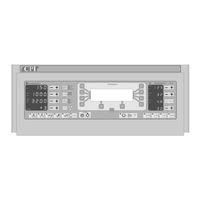
X-RAY GENERATOR
Brand: CPI
|
Category: Test Equipment
|
Size: 0 MB

CPI INDICO 100 Series Operator's Manual (58 pages)
Brand: CPI
|
Category: Portable Generator
|
Size: 1 MB
Advertisement
Advertisement